Corrosion is inevitable when metal and other parts are exposed to the salt air—and especially routinely, as is the case for military ships and other hardware. The Department of Defense (DoD), in an attempt to battle the rigors of nature, has awarded a contract to 3D Systems for research and development in ‘Corrosion Performance Design Guide for Direct Metal Printing of Nickel Alloys.’
While 3D Systems is noted as a leader in the world of 3D solutions and workflow systems, the DoD chose them for the contract due to their capabilities in collecting data on corrosion and then developing new production via direct metal printing (DMP); in fact, 3D Systems technology and expertise are considered to be ideal for creating munitions as well as shipbuilding especially, due to excellent quality control of parts and low oxygen content.
During this contract, 3D Systems will also be partnering with Newport News Shipbuilding and Northrop Grumman Innovation Systems, along with University of Akron corrosion experts. The goal is to reduce maintenance costs in naval sea systems, and as experts in materials science, the team at 3D Systems has excellent knowledge of metals and how they corrode.
“We believe that post-processes for additively manufactured components can be designed to limit corrosion in a saltwater environment,” said Dr. Jared Blecher, principal, aerospace & defense engineering, 3D Systems.
“Through our research and development efforts, corrosion rates will be quantified for additively manufactured parts, so end users will have better data for deciding when parts should be inspected or replaced. Additionally, we’ll explore the value of heat treatment to help improve the mechanical properties of the part and mitigate corrosion and ultimately cost.”
As 3D Systems, Newport News Shipbuilding, and Northrop Grumman Innovation Systems work together to target nickel alloy corrosion difficulties in a list of 240 tests with four different surface finishes, 3D Systems will also be able to make sure that parameters and integrated software are used correctly during evaluation of the issues—mainly seen in naval sea system platforms and high-speed weapons.
The Corrosion Guide will explore how metal additive manufacturing can positively impact shipbuilding and munition fabrication. (Image courtesy of Huntington Ingalls Industries)
The researchers will also use a variety of heat treatments to evaluate the following:
Crevice
Stress corrosion cracking
Galavanic corrosion modes
They will also simulate:
Range of surface conditions
Elemental micro-segregation
Deleterious secondary phases found in deployed components
“There’s no question that the DoD’s need for rapid qualification and certification of additive manufacturing processes like DMP using metal materials like Nickel alloys is great. The creation of a performance design guide by 3D Systems and its project partners will be of tremendous value to the DoD,” said America Makes Executive Director John Wilczynski.
“With qualified empirical data on how to minimize saltwater corrosion of additive manufactured components used in weapon systems, defense supply chains can accelerate their adoption of additive technologies to manufacture these critical components.”
Recent studies have shown that corrosion issues are extremely expensive, costing the U.S. Navy over $8.5 billion a year. Because corrosion is only exaggerated due to traditional manufacturing methods which add stress and weakening, AM processes can offer a host of benefits, plus corrosion resistance. Once corrosion issues are out of the way, not only is there a tremendous savings for the budget, the military can avoid less maintenance time and less inspections.
“We’re excited to partner with 3D Systems on this important effort,” said Charles Southall, vice president of engineering and design for Newport News Shipbuilding, a division of Huntington Ingalls Industries. “Last year, we collaborated to qualify metal additive manufacturing technologies to build naval warships, and installed 3D Systems’ DMP technology. We’re looking forward to expanding that work by developing design standards to help create more durable parts, and ultimately improve the quality of our armed forces’ fleet.”
3D Systems was selected during a competition headed by America Makes, the National Additive Manufacturing Innovation Institute, and the Department of Defense. The program is a Directed Project Opportunity on Advanced Tools for Rapid Qualification (ATRQ), funded by the Manufacturing and Industrial Base Policy Office within the Office of the Secretary of Defense.
This article describes the ideal use-cases for each process & comparison with other solutions to help you identify opportunities using 3D Hubs in your organization for metal 3d printing service.
Definition: End-use part is any good that is either sold as a product or placed in service within a company’s internal operations.
There are 6 processes to consider:
FDM / FFF (plastics)
SLA / DLP (plastics)
SLS / MJF (plastics)
SLM / DMLS (metals)
Metal FFF (metals)
Binder Jetting (metals)
In part 1 we talked about plastic parts, in part 2 we discuss only metals.
4. SLM/DMLS
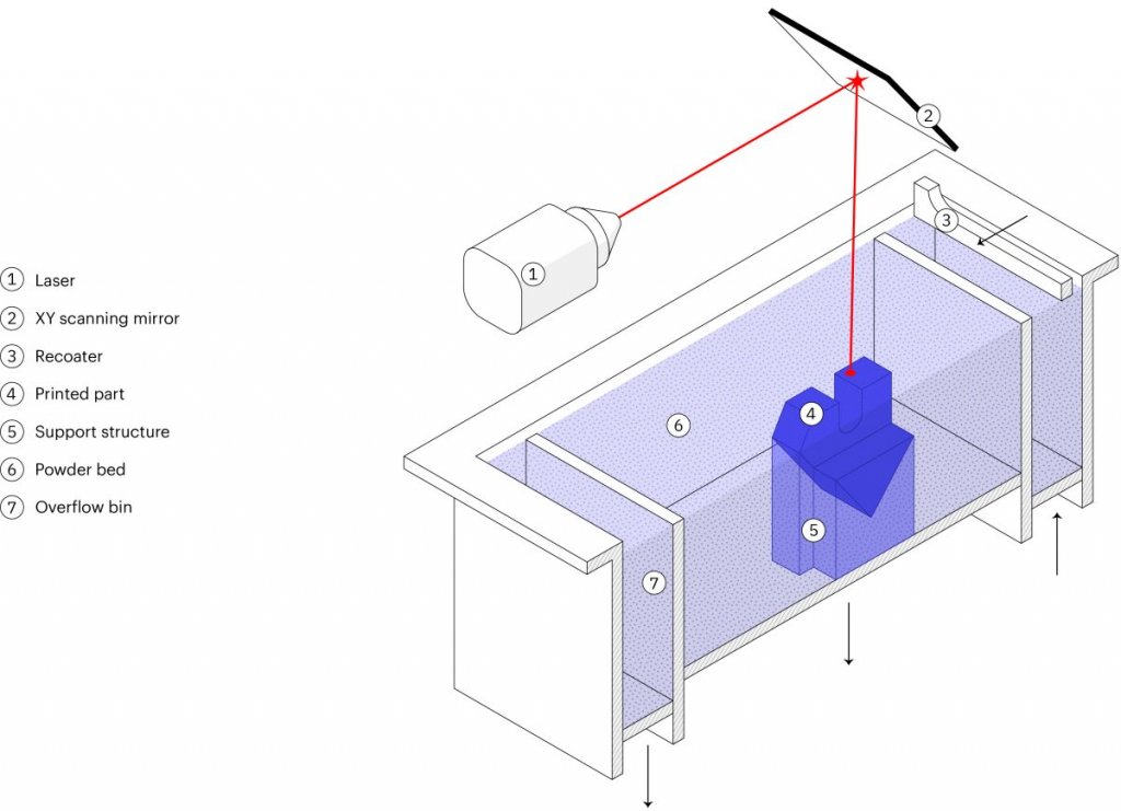
Selective Laser Melting (SLM) and Direct Metal Laser Sintering (DMLS) are metal powder bed fusion 3D Hubs printing processes that are most commonly used today as they are especially suitable for high-end applications since they offer advanced material properties and superb design freedom.
While both utilize high laser power to bond together metal powder particles to form a part– layer-by-layer, SLM will achieve a full melt, while — due to the very high temperatures — DMLS will cause the metal particles to fuse together at a molecular level.
The majority of metal alloys are compatible with the DMLS method, wherein SLM, only certain (pure) metal materials may be used.
Still, the differences between these two 3D Hubs printing technologies are so slim; they can be treated as the same for designing purposes.
In this section, we will take a closer look at the technical characteristics, manufacturing process, and the limitations and benefits of these two, very similar techniques.
How it works: SLM/DMLS 3D Hubs printing process basic steps:
First, the build chamber is filled with inert gas then heated to the optimum print temperature.
A thin layer (typically 50 μm) of metal powder is spread over the build platform.
Next, the laser scans the cross-section of the part, selectively bonding the metal particles.
Thus, the build platform moves down a layer when the entire area is scanned, and the process repeats until the build is complete.
After the printing process is complete, the build must first cool down before the loose powder is extracted.
This step is only the beginning of the SLM/DMLS 3D printing manufacturing process. Once the print is complete, several compulsory and/or optional post-processing steps are also required before the parts will be ready for use.
Compulsory post-processing steps include
Stress relief: Before continuing with any other operation, the internal stresses that develop during printing, due to the very high processing temperatures, need to be relieved through a thermal cycle.
Removal of the parts: In SLM/DMLS the parts are welded onto the build platform and EDM wire cutting or a band saw are used.
Removal of the support: To mitigate the distortion and warping that occurs during printing, support in SLM/DMLS is required. Support is CNC machined or removed manually.
Additional post-processing steps are often required to meet engineering specifications that may include:
CNC machining: When tolerances are tighter than the standard ± 0.1 mm that’s required, machining is employed as a finishing step. Only the slight material is removed this way.
Heat treatments: Hot Isostatic Pressing (HIP) or heat treatments can be used to improve the material properties of the part.
Smoothing/Polishing: Certain application requires a smoother surface than the standard RA 10 μm of as-printed SLM/DMLS. CNC machining and Vibro, chemical, or manual polishing are available solutions.
How it works: Laser source bonds metal powder particles
Strengths:
Geometric freedom
High accuracy & fine details
High-performance materials
Materials:
Stainless Steel
Aluminum
Titanium
Superalloys
Use case #1 – Optimized brackets
DMLS / SLM is used to create lightweight parts through advanced CAD processes, such as topology optimization. They are of particular interest in the automotive and aerospace industries.
Use case #2 – Internal geometries
A far more common use of DMLS / SLM is the creation of parts with internal channels. These find applications in the manufacturing industry (for example injection molding tooling with internal channels for cooling) or for heat exchangers.
Pro tip: Make sure that no support structures are needed to manufacture the internal channels, as they will be impossible to remove.
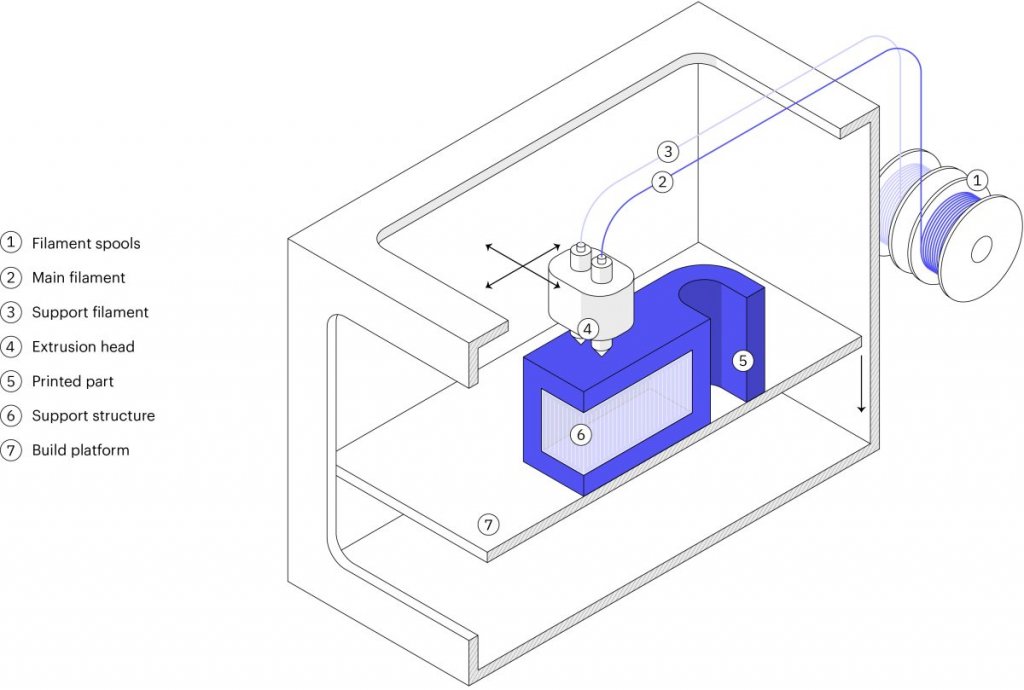
5. Metal FFF: What is metal extrusion?
Metal Extrusion is a low-cost metal 3D printing process alternative that is most suitable for prototyping purposes or for one-off custom parts.
It is a variation of the classic FDM method for plastics. In 2018, the first Metal Extrusion 3D printers were released also known as an Atomic Diffusion Additive Manufacturing (ADAM) and Bound Metal Deposition (BMD).
A part is built layer-by-layer, like FDM, by extruding material through a nozzle, but the material is not plastic, unlike FDM but is a metal powder held together with a polymer binder. The result of the printing step is a “green” part that needs to be sintered and de-bonded to become fully metal.
Here, we examine the characteristics and key limitations and benefits of this additive process to help you understand how you can use it more effectively.
How does metal extrusion work?
Metal Extrusion consists of a three-stage process involving a printing stage, a de-binding stage, and a sintering stage.
The Printing Stage…
Raw material in a rod or filament form, which basically consists of metal particles that are bound together by wax and/or polymer.
This filament or rod is extruded through a heated nozzle and then deposited– layer-by-layer to build a designed part based on the CAD model.
While, if necessary, support structures are built. The interface between the part and the support is printed with ceramic support material that can easily be removed later manually.
When printing is complete, the “green” resulting part must be post-processed using similar steps like Binder Jetting, in order to become metal. The “green” part is washed first for several hours in a solution to remove almost all of the binders. Then it is sintered inside a furnace so that the metal particles are bonded together to form the fully-metal part.
During the sintering process, the dimensions of the parts are reduced by about 20 percent. to compensate for this, the parts are printed larger. Like the Binder Jetting process, the shrinkage isn’t homogenous, meaning that trial and error will be required to get accurate results for particular designs.
How it works: Metal/binder is extruded through a nozzle to print the part, which is then thermally sintered.
Strengths:
Does not require industrial facilities
Based on MIM
Complex metal parts
Materials:
Stainless steel
Tool steel
Main use: For internal operations
An alternative to CNC, Sand casting
Quantity: 1-50 parts
Use case #1 – CNC part replacements
Metal Extrusion is excellent for functional CNC prototyping and small productions of metal parts that would otherwise require a 5-axis CNC machining to produce.
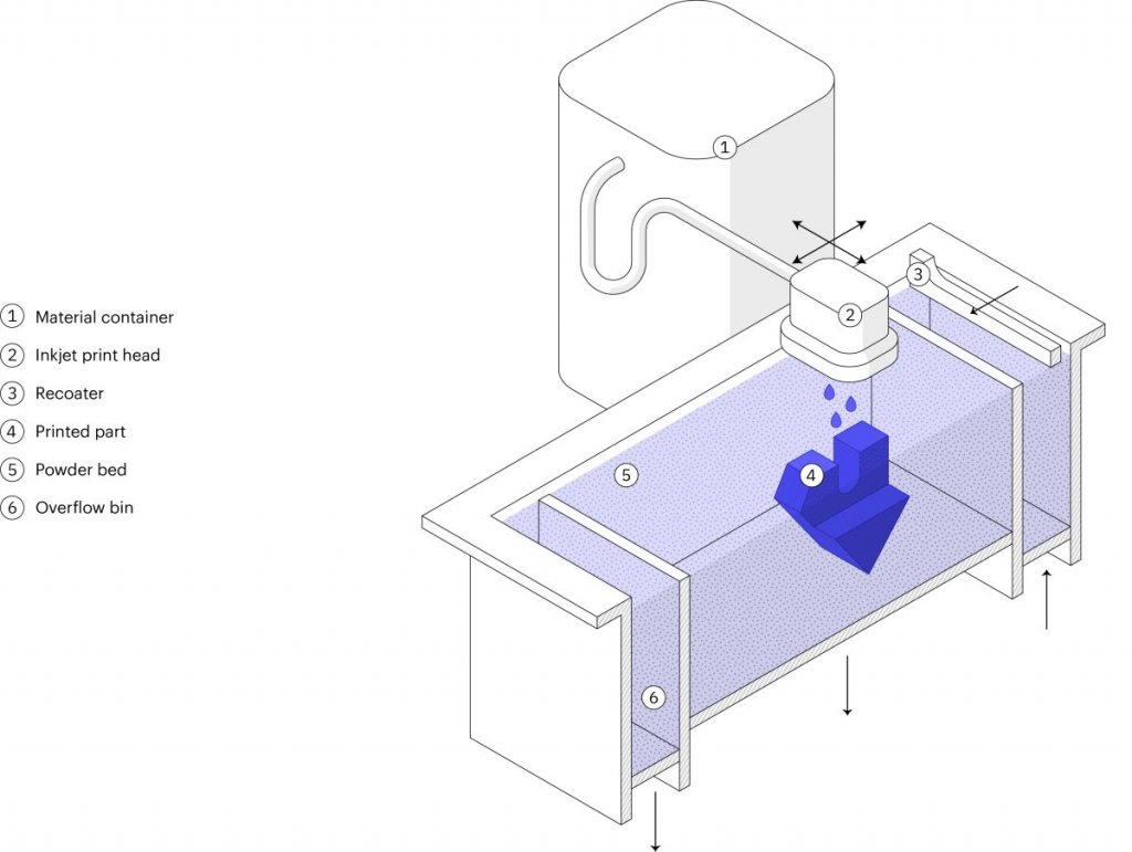
6. Metal Binder Jetting
Metal Binder Jetting is increasing in popularity rapidly. What makes it especially suitable for small to medium production runs, is its unique characteristics.
In this section, we will dive deeper within the steps used in the Binder Jetting to learn the basic characteristics of metal parts production.
What is Metal Binder Jetting?
Metal Binder Jetting is a process of building parts by placing a binding agent on a slightly thin layer of powder in through inkjet nozzles. Originally, it was used to develop full-color models and prototypes from sandstone. A variation of the technique is becoming more popular lately, because of its batch production capabilities.
In metal Binder Jetting printing, the printing step is done at room temperature, which means the thermal effects, such as, internal stresses and warping aren’t a problem, like in SLM/ DMLS, and therefore, supports are not needed. To create a fully metal part, an additional post-processing step is required.
How does Metal Binder Jetting work?
Metal Binder Jetting involves two-stages; a printing stage and a post-processing stage.
The printing process works like this…
A thin layer (typically 50 μm) of metal powder is spread out over the build platform.
A carriage that has inkjet nozzles will pass over the bed while selectively depositing binding agent droplets of wax and polymer to bond together the metal powder particles.
When done, the build platform will move down, then the process will repeat until the entire build is complete.
The result of this printing process is a part of the “green” state. To create fully metal parts and remove the binding agent, a post-processing step is necessary.
This post-processing stage requires two variations: Infiltration and Sintering.
How it works: Binder is jetted onto metal powder particles to create the part, which is then thermally sintered
Strengths:
Great design freedom
Based on MIM
Batch production
Materials:
Stainless steel
Tool steel
Main use: Low-run metal production
An alternative to Metal Injection Molding, Die casting
Use case – Low-run production
Binder Jetting is the only metal 3D printing technology today that can be used cost-effectively for low-to-medium batch production of metal parts that are smaller than a tennis ball.
Why engineers use 3D Hubs for 3D printing
Instant quoting & DFM feedback
Build and edit your quote online. Review your parts for manufacturability and assess the cost of different materials, processes and lead times for your project in real-time. Explore our 3d printing service for every type of additive manufacturing project.
Readily available capacity
Benefit from our network of 250 manufacturing partners to access instantly available capacity. Our manufacturing partners are both local and overseas.
Quality & reliability
Dedicated 3D Hubs team to ensure your parts consistently meet your quality expectations. We also offer phone, email and chat support for any concerns or questions you may have.
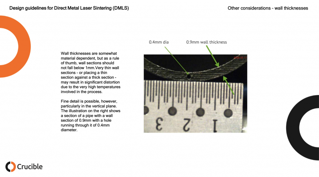
Perchance I came across an excellent document on the design guidelines for Direct Metal Laser Sintering, also called DMLS, Selective Laser Melting, SLM, Laser Powder Bed Fusion and referred to as metal 3D printing. This document was made by UK based design consultancy Crucible Design. Crucible Design was founded in 1990 by Hugh Raymond and Mike Ayre who for the past 28 years have been tackling tough, complex advanced engineering and design projects. Whether working on cost reduction projects or bringing completely new products to market Crucible Design has carefully built up its reputation over the decades. I was so impressed with Crucible’s design guidelines for metal printing document that I asked CEO Mike Ayre if we could republish it here. I also asked him how he came to make it.
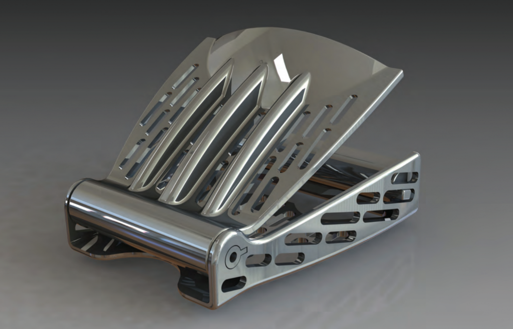
The main reason behind my work with metal 3D printing was the SAVING project, which was run by a consortium in 2011 and 2012. The consortium consisted of Exeter University, ourselves, Plunkett Associates, Delcam, EOS and Simpleware. The point of the project was to find ways to use additive manufacturing to reduce energy use. As the processes themselves are so energy intensive, we soon concluded that the only way to achieve the objective was through the use of the parts, not their manufacture. This is where the airline buckle project came from – reducing the weight of the plane to minimise fuel wastage.
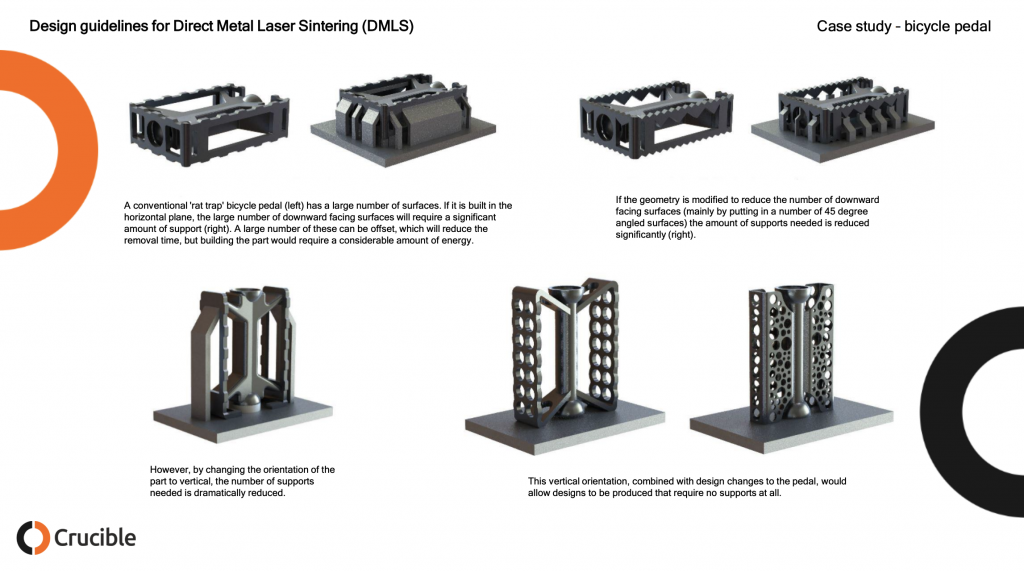
The main problem with metal 3D printing was the same as all design approaches to additive manufacture: early promoters pushed the idea that there were no design limitations, and we ‘were only limited by our imagination’. In fact, this proved to be completely wrong, with 3D printing just having different limitations to conventional methods. In terms of metal printing, the main one is the need to machine out the support structures that are required for any downward facing horizontal surface (the kind of thing that can be washed away using and FDM machine). This requires any efficient design to adopt almost medieval approaches to design, with pointed arches and sloping surfaces that can be built without supports.
Why did you make the guide?
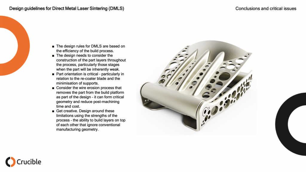
The main reason for making the guide was to inform designers of some of the basic rules and encourage a more creative approach to the use of 3D metal printing and additive manufacture in general. It has been good to see that, since it was written, there is a lot more discussion about appropriate design methods for additive manufacture.
Now the guide was published in 2015 which is eons in 3D printing land. However, the same process limitations and design rules persist. I’ve made design guidelines and design rules documents before and was super impressed with how clear and concise this one was. I think that this is a very valuable resource to people in metal printing today either to learn about designing for metal 3D printing or to use as a teaching aid to help others. If you’re in a design project with a customer then this is also super helpful in trying to let them see that “complexity is free only in dreams.” I am absolutely certain that these images will be spread far and wide, do please credit Crucible Design for their hard work, be mindful that these images are still their copyright and reach out to them should you need any 3D printing design services done. The images below are all Crucible’s the comments are mine.
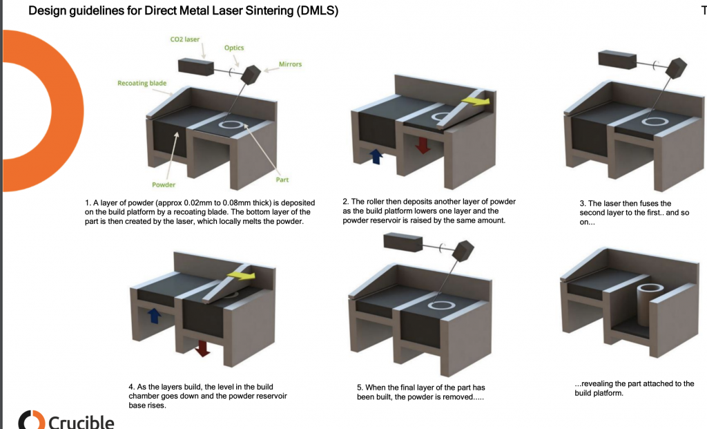
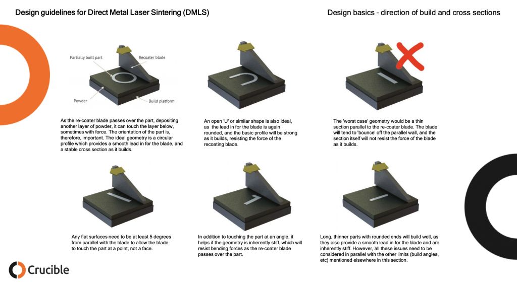
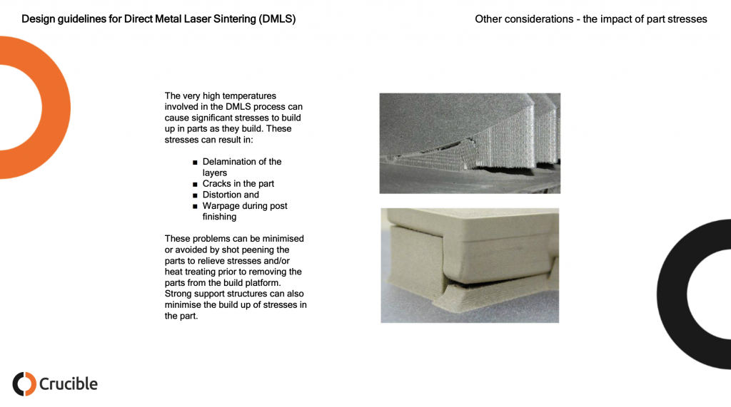
Below we can see how DMLS works. A layer of metal powder around 40 micron in diameter and round but not too round is deposited on a build platform and spread out by a recoater. This may be a roller or a knife blade type of recoater. The laser fuses the powder that will make up your part leaving the other loose powder behind. To keep your part from ripping itself apart due to thermal stress supports are needed which will be removed later.
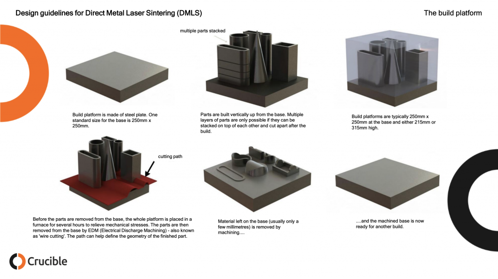
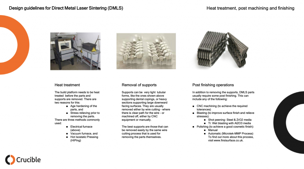
While the build plates below seem very full and indeed parts can be stacked efficiently often single parts are built at a time and parts are not stacked. This has to do with the fact that much of the industry is not yet optimized for production and worry that layer skips or recoater bumps and other errors will disrupt a week long build four days in. Note the high amount of manual labor required here. Every one of the bottom column steps will require a person lifting a few kilos at least to a new station or machine. Not shown here is the manual removal of loose powder. In addition to EDM CNC or tumbling (sometimes for a week or more) may be used as well. Depending on the needed Ra and finish of the part many steps will be required including quality control steps such as CT scanning the part to make sure that there are no internal tears or holes.
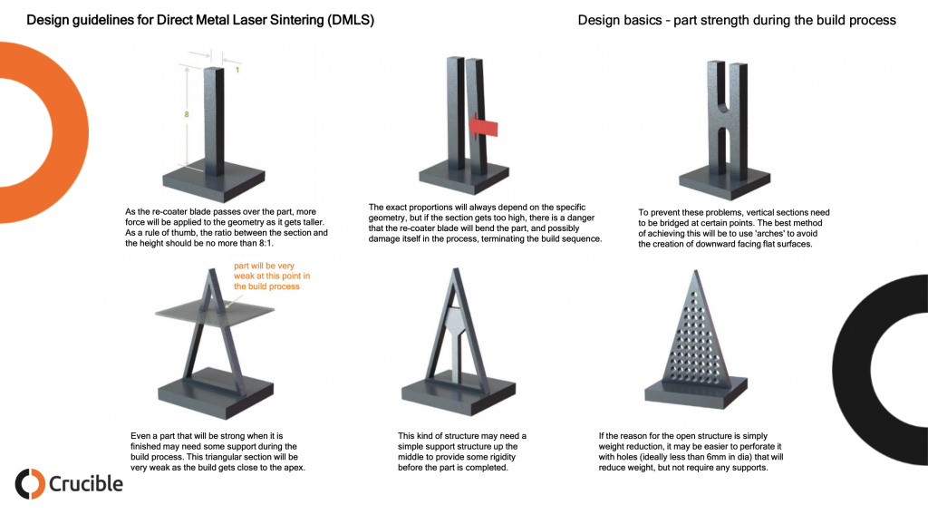
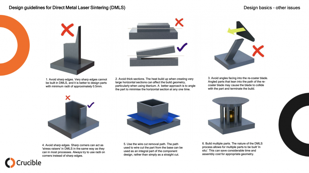
Parts built in such a way as to make it easy for the recoater to hit them with any force and its best to mitigate part strength in such a way that when that does happen your build doesn’t fail.
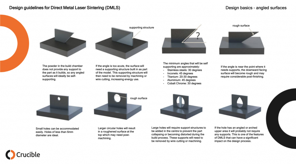
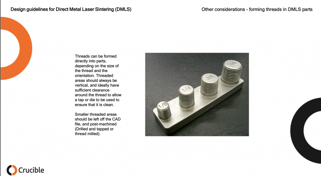
Overhanging surfaces in DMLS can be very rough indeed this may require a lot of post-processing. Occluded holes could trap material inside or require supports that can not be removed while large holes could cause parts to tear themselves asunder.
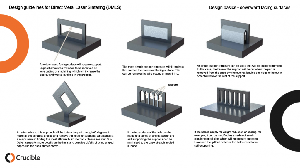
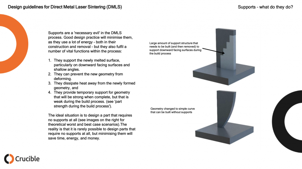
Another thing to consider below is, can the final part withstand the removal of the suports?
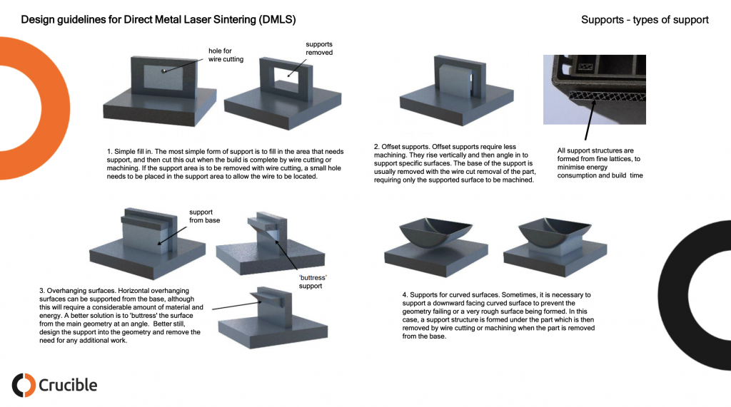
Designing supports that are easy to remove saves a lot of labor. Often a staff member with a flex or circular saw will be cutting away supports. Making sure that this person could do this without damaging the part reduces time and the need to rebuild a part.
Below are some simple support strategies for DMLS. Often a person with decades of experience can do this in their head. While there are some tools that build supports, support strategies for parts still require a lot of experience and thought. Often it will take days for a build and post processing to complete. If you then after four days find out your part has failed then you have to do another iteration. When making completely new geometries several part failures are common. If you have a type of geometry understood (acetabular cups, teeth) then you can print millions of them in many variations.
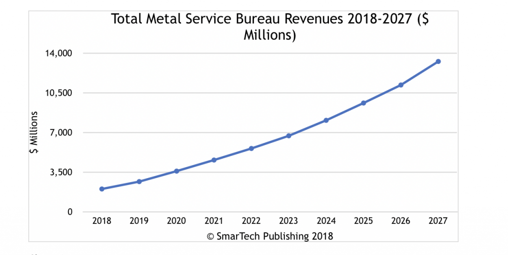
Leading industry analysis firm, SmarTech, just published a report on emerging metal printing opportunities for 3DP service bureaus.The new report, Metal 3D Printing Services: Service Revenues, Printer Purchases, and Materials Consumption – 2018 To 2027, contains corporate profiles (showing how leading service bureaus are taking advantage of metal printing), and granular 10-year forecasts, with break outs by industry verticals, types of metal, type of printers/3DP processes, uses and types of metals printed.
This report is the first from a new group at SmarTech which is focusing on service bureau opportunities.The SmarTech team is currently at work building a comprehensive forecasting model for service bureau revenues, printer purchases, install base, and materials consumption.This work will be based on the many studies of industry verticals for 3D printing undertaken by SmarTech over the past six years.
Metals 3DP and Service Bureaus: A Dilemma
Lawrence Gasman, President of SmarTech and author of the study, says that metal printing by service bureaus alone will generate $6.7 billion in revenues by 2023.According to Gasman, metals printing will be especially important to service bureaus.“Metals printing is more complex and harder for end-users to take ‘in house’ than polymer printing,” says Gasman,“but SmarTech’s research indicates that metal printing may be less profitable than polymer printing for bureaus.This is the paradox.From the service bureau perspective, metals printing may be where the growth is, but at the same time bureaus focusing more on metals could find their profit margins eroded.”
The new SmarTech report discusses ways around this dilemma including specialization in certain market verticals or in certain metals.However, it concludes that sustainable competitive advantage in the metals service bureau will come from two strategic approaches.One of these involves “hub networks” that distribute the responsibility for printing metals jobs booked by the hub company to many service bureaus based on geography, capacity, and technical capabilities. “Using proprietary software, hub networks can create efficiencies that can offset lower margins on printing metal products,” says Gasman. The SmarTech report also notes that making the actual metal printing part of a higher value-added offering that includes design and technical guidance will also be an important strategic route to profitable success for metal service bureau.
Medical, Dental and Metal
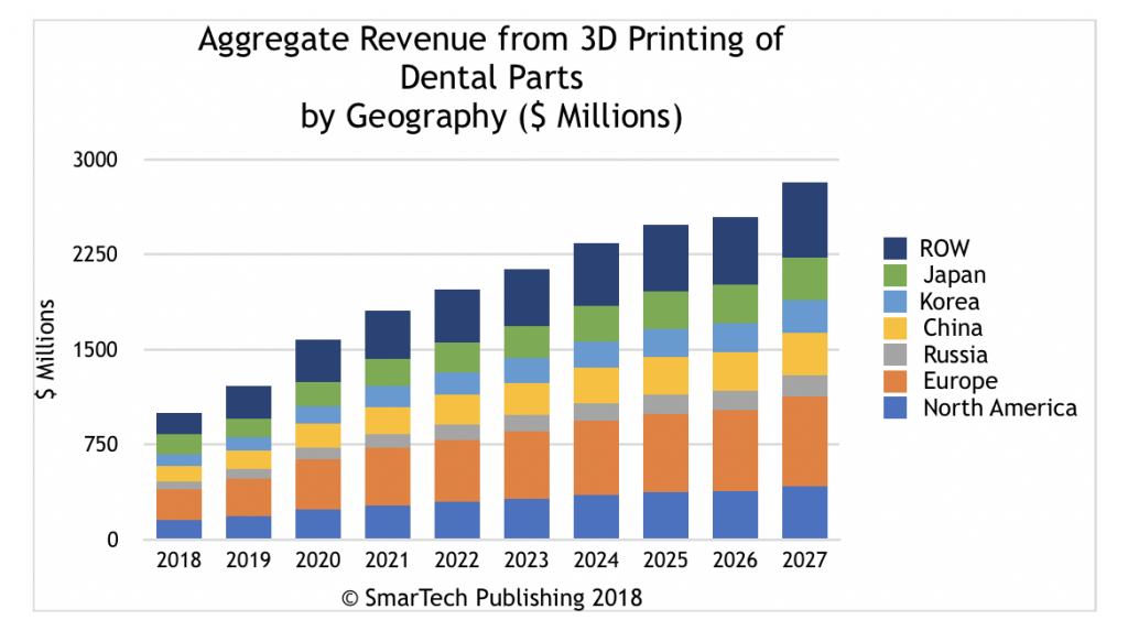
In addition to the usual suspects (automotive, aerospace, oil and gas), SmarTech reports that metal printing by service bureaus are expected to generate considerable revenues from the medical and dental sectors. While, much medical 3DP is polymer-based, there are important exceptions.Metal implants are mostly Ti64, commercially pure titanium or cobalt chrome alloys such as MP1.
Titanium alloys are the go-to implant material for orthopedic implants providing lightweight, biological inertness, and the ability to function as a load bearing implant.But despite the criticality of these materials, printing of these (and other) metal implants with PBF simply cannot be done in primary care environments due to requirements for safe handling of reactive materials, post-processing and post heat treatment requirements, and testing.And even though there is a general trend towards bringing medical/dental care closer to the patient, the fact that printing metals is not an easy thing to do will make this trend a slowly acting one.
This provides some advantage to metals service bureaus.“What we are seeing,” says SmarTech’s Gasman, “is that while some of the larger medical device leaders have begun investing more heavily in the internal production of additively manufactured implants, OEMs remain significantly focused on outsourcing to service bureaus in order to focus down on core competencies and R&D.However, bureaus planning to exploit this particular opportunity will have to acquire a high degree of specialization and process expertise.”
Meanwhile, in the dental sector, the equivalent of service bureau (confusingly still called milling centers), the 3D printing of metals is focused onproducing metallic elements for porcelain-fused-to-metal (PFM) dental restorations and the metal hardware for dental implants (including the screw and the abutment to which the visible tooth-like portion of the implant is affixed). By 2023, SmarTech believes that over half service bureau revenues associated with metal printing will come from printing dental or medical products.Conversely, print services are expected to drive a majority share of total opportunities associated with medical and dental 3D printing in general.
Back in the 3D printing dark ages, 2005, David Burns joined ExOne to make manufacturing using 3D Printing a reality. In the ensuing thirteen years a lot of things have changed. We’ve seen a lot of 3D printing companies come and go. In 2005 “3D printing for manufacturing” was cute and only a few solitary voices were crying out that this was going to happen, David’s was among them. He and ExOne were tackling quality control, reliability, and repeatability back then; and trying to make 3D printing an industrial process. They were starting to manufacture tens of thousands of low-cost metal parts for customers. They along with Voxeljet were the only metal inkjet companies as well, whereas now there are over a dozen people in various stages of commercializing metal inkjet 3D printing technologies. Entire choruses, unburdened by knowledge or experience, are now crying out that 3D printing for manufacturing is the future. David meanwhile, was doing the heavy lifting (and an IPO) while many of you had probably never heard of 3D printing. Now that he’s an independent board member, advisor and consultant its time for him to reflect on his time in the 3D printing trenches with some insightful answers to 3DPrint.com’s questions.
You came to 3D Printing in 2005 from a background in manufacturing. What was the 3D printing landscape like back then?
“In the life of products, 2005 seems like a century ago. We used to laugh, as we evangelized for this “ground breaking” technology, that people used to pat us on the heads and say ”oh, that sounds nice.” There is no doubt that in 2005, the general sentiment was that 3D printing was a curiosity and not a serious technological thrust. This impeded progress in many ways, not the least of which was that critical R&D dollars were slow to flow to 3D printing.”
And now?
“Oh, how the landscape has changed. The sentiment among end-users is no longer about “if we will succeed”, but rather a clear sense that “we will succeed”. On a global basis, we can see a determination (and almost desperation) to fund emerging ideas and to see them through to either success or failure. Of course, that applies as well to all of the supporting and enabling technologies that surround 3D printing, like software, materials, inspection, sensor technology, data transmission and storage, etc. Clearly, we need success in all aspects of this technology circle to develop simultaneously.”
What are the most significant improvements over the time frame?
“The last few years have seen the emergence of some pretty surprising innovations in 3D Printing itself. This includes a really impressive array of machine-based approaches, often combined with robotics and AI to fully integrate functionality within lines. And, there has been an interesting but quiet trend to “hybridize” traditional manufacturing technology approaches with additive approaches.”
There is still a lot holding back 3D printing in manufacturing today. What are some of the main issues?
“Well, one of the most important elements of an effective and robust manufacturing environment is a commitment to continuous improvement. So, in that context, I see two short term areas of focus that would really help.
The first would be investment in process stability. It has become a source of pride in many manufacturing environments that the basic deviation patterns of outcomes is well understood and controlled. Most 3D Printing lacks the basic process stability that is so necessary for volume production.
The second would be the need to extensively (and rapidly) expand the suite of material that can be effectively printed. The good news on the material side is that 3D Printing allows for new, customized materials to emerge.
I want to be sure that I make one point, though. I see these issues as eminently solvable. With a robust R&D funding environment, these basic challenges will be overcome. It is simply a function of the quantity and speed of investment that will determine how fast that we overcome them.”
QA seems very poorly developed in 3D printing?
“I want to change the language of that question a bit. Continuous improvement methodologies exist which can be directly applied to 3DP and to move it forward, in the QA sense. You can see mounting evidence that it works….but I do want to provide a caution here. We need entrepreneurs to understand that there are well-proven processes within manufacturing that cannot be ignored. I do worry, a bit, that some companies are trying to approach the industrial marketplace with little experience, or little sense of the long manufacturing journey toward optimization.
I do understand why it may feel as if QA is lagging in 3DP, since there are consistent deviations in even part-to-part characteristics. But, with the application of continuous improvement processes, and the injection of research dollars at the right time, these knotty problems are resolvable.”
In metals, a lot seems to be going on right now, with investment pouring in and much excitement. What are the companies that you are closely watching?
“Part of my work involves being a general advisor to AMT – The Association for Manufacturing Technology. But part of my time is allocated to providing advisement services directly to manufacturing companies, some of which are 3DP companies. So, it is probably not fair for me to specifically name companies that I find exciting. That said, manufacturing is a broad-based, global activity. I do tend to get excited by metal printing companies that are clearly focused on end-user needs, and not simply enamored by their own technologies. I also do not see the need for emerging companies to feel the need to print the toughest materials, in the toughest applications. There are a myriad of opportunities for companies that want to compete on the well-established measures for manufacturing – cost, quality, and on-time delivery.”
I’m a little more skeptical than most about binder jetting metals. Won’t shrinkage continue to be problematic? Or will they solve these issues?
“Well, questions about binder jetting hint at some of the things that we just discussed. Some binder jet companies are, in fact, looking to the MIM world for ideas about controlling the sintering process. And there are surely helpful answers there. Others have invested significant dollars and have found ways to increase density and lessen distortion. I think that offline sintering can pose a significant challenge – but that sufficient research can find innovative solutions. I am not entirely sure that the challenges posed by off-line sintering imply significantly more part-to-part variation than some of the other powder bed based processes. And I do see cost advantages in binder jetting. I think that there will be a healthy number of applications for which binder jet will be appropriate.”
We’re seeing new companies try to tackle low-cost metal parts. Which kinds of parts will be industrialized first?
“Well, the low-cost marketplace poses some challenges. Material and energy-related costs present initial hurdles that need to be overcome. That said, there are lots of parts which run in relatively low volumes and that require significant fixturing and changeover on traditional machines. These are good targets. As well, many of those sorts of parts have been sourced from remote locations, for reasons that we all understand. If we do a realistic analysis of true supply-chain costs, including communications, working capital, quality resolution, etc., then I see abundant opportunities for 3D Printing.”
Do you think that in the near term there will be direct competition between the new binder jetting companies and the DMLS (Powder Bed Fusion, Selective Laser Melting) companies?
“Perhaps not in the very near term. The strengths of each process are currently a bit different. That said, as more materials become available, and as the part-to-part consistency improves, competition will (and should) develop. Remember, the annual market for traditional manufacturing technology products (on a global basis) is between $90 – 100B. Inside of that is a massive market for machines. While some of those machines are for specialty purposes, the vast majority are “part agnostic”. That is, they can be used for a wide range of parts. I think that this is the inevitable evolutionary path for machines used for metal 3DP.”
How do you think the metal printing market will develop?
“I think that the answer to that may vary by region of the world. In the US, which imports massive numbers of metal parts from other places, I think that the acceleration will be rapid. I can easily see where service bureaus that have broad-based capabilities (including traditional processes, inspection, and certification) will grow very rapidly, as the supply chain adjusts to the power of integrated digital manufacturing technologies. I think that OEM’s may invest more slowly than service bureaus, but it does not matter. What matters is that the supply transitions to embrace these new, integrated manufacturing technologies. In other countries, the transitional challenge may be different. In countries that are heavily invested in manufacturing infrastructure, the decision to disinvest in their well proven, highly capitalized processes could be harder. Clearly, the emergence of product offerings that are full lines (many recently) are reactions to the challenge of displacing well-developed, effective manufacturing processes.”
Whats the thing that surprised you most in 3D printing?
“That is a hard question. I became interested in, then immersed in, 3DP quite a long time ago. I perhaps saw the immense potential, from a high-level perspective. But, with a background in traditional manufacturing (which is quite effective and which I greatly respect), it was not clear how 3DP would ever become robust enough to displace that traditional structure. Especially when I thought about the immense quantity of investment that would be required. I think that a key transitional element has become the willingness of OEM’s to take a leadership role in the development of advanced manufacturing technologies. In the past, these same companies were relatively content to allow the supply chain to evolve manufacturing technologies. Nowadays, you have end users directly involved in funding and guiding that development. The final surprise, for me, is actually how powerful this combination of software, hardware and materials can be in changing our world. The applications that have emerged and are stunning and make the world a better place. I cannot wait to see what happens next.”
Velo3D raised $22 Million in 2015 and was working in secret to revolutionize metal 3D printing. For the past years the company has been quiet as a mouse about its process and intentions. A lot of speculation abounded as to what Velo3D could unleash upon the world. Today we learn that the company has developed a metal printing process with more design freedom in metal. The company says that its systems can print complex geometries below 45 degrees. Which would make more 3D printed parts possible with their technology. The company has also developed its own software to acompany its process. And rather than just raising $22 million it turns out that they’ve raised over $90 million in funding. 3DPrint.com interviewed Stefan Zschiegner, Chief Product Officer at Velo3D, about the secretive start up now coming out of stealth mode. From their answers, their published work and patents we can conclude that this is a well captilalized start up with a lot of candle power that seems to have gotten quite far in controlling for many the important variables in metal 3D printing.
Acetabular Cups 3D printed on a Velo3D. We can see that in terms of the sheen and the look of this that it is very different from the usual output of metal 3D printers.
Why all the secrecy?
The model for Silicon Valley has typically been to announce and hype products long before they are commercially available. For a solution like the one we are bringing to market which aims to disrupt the $500 billion global manufacturing industry, we felt it was necessary to wait until we had a thoroughly vetted, customer tested product available for sale before announcing ourselves to the world.
Unpacking Acetabular cups (for giants) with the Velo3D.
What’s special about Velo3D?
We started Velo3D with a bold vision to enable additive manufacturing without design constraints. We are solving problems with deep insights and getting to the root cause. Based on that we build a solution from the ground up for high volume manufacturing consisting of our Sapphire System and Velo3D Flow print preparation software. Intelligent Fusion is the technology that powers the combination of Flow and Sapphire and enables an end-to-end integrated workflow.
While conventional systems often require supports for any geometry below 45 degrees, Velo3D’s Sapphire uniquely enables engineers to realize designs with overhangs lower than 5°and large inner diameters without supports.Some of our key benefites include
1st print success rates of 90%
Reduced part costs by 30-70%
Look at the teeny tiny blue windows, not sure what is going on in there but it is very powerful and plasma-y. Am I the only one getting a kind of DoD InQtel feel from this?
Is this a manufacturing technology?
Yes, Velo3D is a metal additive manufacturing solution company. Our customers are service bureaus who offer metal 3D printing services to end users, as well as leading OEMs for use in-house.
What kind of parts can be made with your technology?
We have removed design constraints by enabling overhangs below 5 degrees and large internal openings up to 40mm. Key applications include shrouded impellers, heat exchangers, pump housings and other turbomachinery components which are critical for the aerospace, energy and industrial applications. We also enable medical instruments and implants, such as orthopedic hip cups.
You state that more geometries can be made? How?
The ability to design and print complex geometries is enabled by our Intelligent Fusion technology. Intelligent Fusion is a Velo3D proprietary technology invented to free the conventional powder bed laser fusion approach from design constraints through process simulation, prediction, and closed loop control.
An impeller 3D printed by Velo3D.
Did you manage to correct for melt pool size in order to improve microstructure control?
Yes. Microstructure control is only one of Velo3D’s benefits. It allows us to build previously impossible designs and to improve part-to-part consistency.
What kind of reliability and repeatability are you getting?
We are meeting and exceeding reliability and repeatability tests by our customers. Currently we are testing with external labs and plan to publish the results soon.
A Shrouded Impeller Printed on the Velo3D, note the supports on the bottom.
How dense are parts?
The parts meet and exceed metal manufacturing density requirements of over 99.9%.
What kind of Ra are you getting off the machine?
The surface properties are geometry dependent and customer application defined. We are demonstrating below < 3 SA.
Both Impellers.
What post processing typically needs to be done?
The Velo3D solution minimizes the need for supports reducing typical support volume 3-5 times. It avoids internal supports that prevents the manufacturability or causes laborious post processing with conventional approaches.
Who are your target customers?
Service Bureaus and OEMs with expertise in additive manufacturing.
A stator ring and impeller
What are your target applications?
Aerospace, energy and Industrial applications, as well as medical applications (i.e., orthopedic implants). Applications include engine parts such as impellers, heat exchanges, and other critical turbomachinery parts, as well as assembly simplifications but also spare parts and spine implements, and larger implements such as hip cups.
Velo3D has come out of nowhere to seem quite the contender. If their estimates and performance claims pan out in the real world then this is a very interesting technology indeed. Simulation is very difficult to do in metal 3D printing and its a key element of getting prints right. Finding out $5000 and three days later that your parts don’t work kind of holds the technology back. This opens up new applications for 3D printing. Especially if they can have a sucess rate of 90% on the first time printed parts. Sometimes in Powder Bed Fusion you have to come up with different support strategies and print a part four or five times to get it right if it is a new geometry. Powder Bed Fusion in metals is great at making a million different hip cups but if we’d throw a radically different shape in the printer for the first time than this will most likely fail. Many applications are being held back because of this. Think of “draw your own jewlery” as a start up idea for example. Reducing supports will also make this much cheaper in terms of overal part costs and may save time as well. Supports are still manually removed on, nearly all, Metal Powder Bed Fusion 3D prints. You can see how parts are being unpacked on the Velo3D here. Manual removal of supports adds considerable cost to the final part so any gain here would be very beneficial. The increased design space could open up new applications, especially in new customers that have thusfar been unable to make their parts with metal 3D printing.
3D printing is very much a testing and data game if you want to take on manufacturing. You’ll need hundreds of kilos of a powder to make sure it works well for example. There are also many geometries that can have significant effects on how and if the part builds. Thermal stresses can cause parts to get ripped apart as well. By developing simulation software the 100 strong Velo3D team has really focussed on getting the repeatability right through lowering their testing cost and increasing their dataset. This is a smart move and will bring dividends to them and their customers. The company has a number of patents including a skillfull 3D printing one, an accurate 3D printing one and an adept 3D printing one. Also the first time I’ve ever seen cute patent names. Going by those patents the company has developed a real time melt pool monitoring technology that works in concert with material dosing and laser control and builds closed loop using, probably, a plasma beam.The company seems to also to be able to correct on the fly with cooling to reduce deformation and may use an FPGA or similar to do this. So depending on errors it seems to be able to reduce the insensity of the laser or actively cool a part. Given the teams previous work and published articles they may also be using a MOSFET or Field Effect Transistor to do this.
Also given that velocity fields play an important role in metal 3D printing and the name of the company is Velo 3D, I’m taking a guess here to say that they probably are managing to control velocity fields in some way which would then allow them to have more of a grip on the final part and how it is built. If they then are able to monitor melt pool size and shape in real time using the FPGA and then have influence on the cooling rate of areas of the part while being able to adjust the plasma beam also on the fly then they may have just come close to cracking this metal printing thing. They certainly have the candle power to do it, they’ve hired very bright people who have over the years written some very interesting papers on real time monitoring, modeling and control of metal 3D printing. During my research for this I was actually at one point surprised to learn that Brent Stucker didn’t work at Velo3D now given the overlap.
The patents also seem to disclose that parts can be polished and post processed in part by lasers on the build machine, perhaps in concert with building the part. Another patent seems to point to active cooling or producing multiple layers at once using a preheat step or process. Can’t wait to find out how this actually works. All in all the value propostion seems a solid one and they’re certainly ticking the right goals. They’ve also got a lot of air which they can use to iron out the kinks in the chain. I like the fact that the company seems down to earth and isn’t all “startuppy” about everything. But, first impressions are first impressions and we work in an industry where an awful lot of machines and dreams have caught fire. We’ll have to wait to find out what the performance is as tested or experienced by the customer, it will cost me some beers at a trade show but I’ll find out for you guys.

 While 3D Systems is noted as a leader in the world of 3D solutions and workflow systems, the DoD chose them for the contract due to their capabilities in collecting data on corrosion and then developing new production via direct metal printing (DMP); in fact, 3D Systems technology and expertise are considered to be ideal for creating munitions as well as shipbuilding especially, due to excellent quality control of parts and low oxygen content.
“We believe that post-processes for additively manufactured components can be designed to limit corrosion in a saltwater environment,” said Dr. Jared Blecher, principal, aerospace & defense engineering, 3D Systems.