What is Metrology Part 8: Complex Analysis, Optics, and Metrology

The field of metrology is interesting for me as it integrates a lot of what I enjoy in physics and technology. The field from the outside seems very bland, but when you delve into the background, it becomes a more colorful picture. The field is reliant on the physics behind optics and image processing. These are areas of extreme interest to me. Visualization and capturing visualization data is essential for the field. A lot of this data is difficult to interact with as well because the data must be interpreted as a function that can be manipulated for reconstruction purposes from point cloud data. The mathematics behind this is what can be referred to a complex analysis. Today I will give some basic insight into these advanced concepts of physics and how they open us to learning more about metrology and 3D scanning. 

Let’s first talk about the field of optics. Optics is the branch of physics that studies the behaviour and properties of light, including its interactions with matter and the construction of instruments that use or detect it. Optics usually describes the behaviour of visible, ultraviolet, and infrared light. Because light is an electromagnetic wave, other forms of electromagnetic radiation such as X-rays, microwaves, and radio waves exhibit similar properties.

Optical science is studied in many related disciplines including astronomy, various engineering fields, photography, and medicine. Practical applications of optics are found in a variety of technologies and everyday objects, including mirrors, lenses, telescopes, microscopes, lasers, and fibre optics, as well as metrology practices.


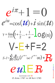
Yes Imaginary Numbers are useful

I personally have a strong fascination with the field of optics. Firstly, I wear glasses and my glasses help me “see” more. The field of optics quickly takes a dive into metaphysical thought processes on human perception as well as what we actually see. Optics is the center of how most of us “see” the world. When we are in the field of metrology we are relying on man-made technology to measure what we see as humans. The realization that we as humans are measuring reality and physical dimensions is a bit mind-boggling. We do not necessarily know what reality is, but we use metrology to measure for us what is within our “grasp”.

Here is where it starts to become a bit more interesting. What defines the system we are in as humans who are measuring within their current state of reality? There must be a larger system that allows for this to occur. This is where complex analysis comes into play. Complex analysis, traditionally known as the theory of functions of a complex variable, is the branch of mathematical analysis that investigates functions of complex numbers. It is useful in many branches of mathematics, including algebraic geometry, number theory, analytic combinatorics, applied mathematics; as well as in physics. As a differentiable function of a complex variable is equal to the sum of its Taylor series (that is, it is analytic), complex analysis is particularly concerned with analytic functions of a complex variable (that is, holomorphic functions).

Complex Analysis 3D Function

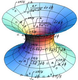
For those of you intimidated by math, I will explain the meaning behind the math. Complex analysis is the branch of mathematics that is trying to understand the imaginary or complex plane of the universe we are confined to. We are working within 3 degrees of freedom or 3-dimensionality within our universe. The system of the universe is not determined by what is seen in the 3-dimensional world. Our perception is not what easily moves the universe. The forces that work on our 3-dimensional universe are applied through the fourth dimension or the complex plane of the universe. For all those who want to learn more physics be sure to enjoy immense philosophical implications. So why is all of this relevant to metrology and optics? Think about this. The signals or data we receive from viewing images is distorted by the complex realm. If it was not, there would be extremely high resolution images taken on a consistent basis. That tiny bit of blur in a photo, for example, is a byproduct of the complex world interacting with the physical realm we are within. This is what typically creates a noisy signal typically in physics. In signal processing, noise is a general term for unwanted (and, in general, unknown) modifications that a signal may suffer during capture, storage, transmission, processing, or conversion. Noise reduction, the recovery of the original signal from the noise-corrupted one, is a very common goal in the design of signal processing systems, especially filters. The mathematical limits for noise removal are set by information theory, namely the Nyquist–Shannon sampling theorem.

The data we are collecting, or information, is prone to noise. We live in the 3rd dimensions and the complex plane consistently is interacting with our signals or data. Thus we use filters to help with noise cancellation. This is the basis of image processing and digital image reconstruction. The algorithms being created currently for photogrammetric filters are extremely vital for the future of 3D reconstruction. These filters will rely heavily on the field of complex analysis to build better filters. Then we will have very clean 3D reconstructions from our metrology practices. For all those who are intrigued, I will continue to explain different items within the 3D metrology field.

The post What is Metrology Part 8: Complex Analysis, Optics, and Metrology appeared first on 3DPrint.com | The Voice of 3D Printing / Additive Manufacturing.

What is Metrology Part 6: Perceptron

Perceptron

Perceptron (NASDAQ:PRCP) was founded in 1981 by graduates of The General Motors Institute (formerly GMI and now Kettering University). Working closely with the automotive industry, they analyzed and understood the damaging effects of process variation on complex product assembly operations and concluded that “a process which cannot be measured can never be effectively controlled or optimized.” Through revolutionary machine vision and pioneering engineering efforts, they created a unique and innovative measurement solution that not only allowed fast and efficient containment of quality problems as they occurred, but also provided the ability to proactively seek-out and reduce process variation. The result was groundbreaking – a 100%-dimensional measurement solution capable of being deployed in various manufacturing environments. They have continued to leverage industry expertise, global infrastructure, and comprehensive range of solutions to further penetrate the automotive, manufacturing, appliance, aerospace, and heavy machinery markets. Headquartered in Plymouth, Michigan, USA, Perceptron has subsidiary operations in Brazil, China, Czech Republic, France, Germany, India, Italy, Japan, Singapore, Slovakia, Spain and the United Kingdom. Today we will do a brief look at their company as well as their metrology technology. 

Perceptron creates products based on an organization’s needs. Products of theirs include 3D machine vision solutions, robot guidance, coordinate measuring machines, laser scanning and advanced analysis software. Global automotive, aerospace and other manufacturing companies rely on Perceptron’s metrology solutions to assist in managing their complex manufacturing processes to improve quality, shorten product launch times and reduce costs. The customers of theirs include Nissan, Masserati, Whirlpool, Jeep, Land Rover, GM, Audi, Magna, Maserati, Mercedes Benz, Volkswagen, BMW, Ferrari, Chrysler, Jaguar, Ford, Hyundai, Lamborghini, and SEAT. They create non-contact sensors that use a high resolution camera and various laser colors to achieve reliable measurement on bare and painted metal, chrome, translucent materials, carbon fiber, and other materials at full production speed. All sensors are also calibrated and rectified at Perceptron’s headquarters and ship ready to measure. 

Some of their main products in terms of laser scanning and 3D metrology include the following:

  • Helix – evo
  • Helix – solo
  • V7

Helix – evo

The Helix- evo is a 3D scanning sensor that is optimized for in-line measurement. It does best in a manufacturing or on a plant floor. 

Helix – solo

Whereas the evo is meant to measure many measurements of a workpiece the Helix-solo only contour measures one. 

V7

The V7 is a device that integrates with other CMM machines. This 3D scanning tool enables reverse engineering, point cloud-to-CAD comparison, 3D visualization and inspection applications.

A key difference between Perceptron and other organizations previously analyzed within this metrology series is the fact that they are currently traded publicly as a company on the NYSE. The current stock price as I write this article for Perceptron (PRCP) is $4.39. I am not traditionally trained in analyzing companies and their SEC filing info, but for those who are inclined, I have attached the link to Perceptron’s filing here.

It is apparent that the majority of their sales seem to come from their general measurement solutions. The company is based on standard metrology, but 3D scanning solutions are not as large in terms of sales just yet. It is still a large amount of sales, but it is far away from being the main focus of this organization. This also may point towards the fact that 3D scanning is still in its infancy in some sense. Again, I am not a qualified financial expert, just giving an opinion based on my background. Would love to talk to someone with more knowledge. 

This concludes my basic analysis of Perceptron as an organization. After doing this, there are still a ton of questions and follow ups I will be doing. I am excited to be understanding the market of 3D scanning a bit more as this will be connected to the 3D printing field for a large amount of time. 

The post What is Metrology Part 6: Perceptron appeared first on 3DPrint.com | The Voice of 3D Printing / Additive Manufacturing.

What is Metrology Part 2: CMM

Image result for cmm

CMM

A CMM is a widely used machine used to measure objects. A CMM is a coordinate measuring machine. This refers to any machine that measures the geometry of physical objects by sensing discrete points on the surface of the object with a probe. This is the essence of many a metrology system. The precision of a CMM is vital for determining the geometry of objects. This then leads to more precision in the manufacturing and replication of objects. 

Probes are the engine of a CMM. They sense objects through their surfaces. There are various types of probes as well.  The types of probes used in CMMs include mechanical, optical, laser, and white light. Mechanical probes typically have a ball and rod looking setup attached to them, or have a nozzle setup. These physically touch the surface of a material that is in need of measuring. Optical probes typically refer to spectral analysis and measuring through these means. One can think of a fiber optic probe in particular. These type of probes are usually used in Raman spectroscopy, and diffuse reflection applications. Raman spectroscopy is a spectroscopic technique based on inelastic scattering of monochromatic light, usually from a laser source. Inelastic scattering means that the frequency of photons in monochromatic light changes upon interaction with a sample. The scattering of the photons within a monochromatic light source allows for a device to detect if an object is within the path of monochromatic light. This thus leads to measuring capabilities that are important in terms of a CMM as well. Diffuse reflection is similar to Raman Spectroscopy aside from the optical source is typically infrared. When an IR beam passes through a physical object, it can be reflected off the surface of a particle or be transmitted through a particle. The IR energy reflecting off the surface is typically lost. This transmission‐reflectance event can occur many times in the object, which increases the pathlength. This pathlength is vital for measuring. Finally, the scattered IR energy is collected by a spherical mirror that is focused onto the detector. The detected IR light is partially absorbed by particles of the object, collating the object information.

Image result for raman spectroscopy

Typical Raman Spectroscopy Setup

A CMM is heavily reliant on a built-in coordinate system of, typically, three axes. This is similar to the coordinate systems we are aware of within a 3D build environment. This is a Cartesian Coordinate system. The main structure of which includes three axes of motion. The material used to construct the moving frame has varied over the years. Granite and steel were used in the early CMM ‘s. Today the major CMM manufacturers tend to build frames from aluminium alloy or some derivative and also use ceramic to increase the stiffness of the Z axis for scanning applications. CMM axises need to be stiff because there should be minimal outside inference with forces that may misalign the device during measurement. Any misalignment will cause higher error ranges for measurement. 

Image result for cartesian coordinate system

Cartesian Coordinate System

Scanning techniques are becoming more reliant on data collection and compilation. These methods use either laser beams or white light that are projected against the surface of a part. Thousands of points can then be taken and used not only to check size and position but also to create a 3D image of the part also. This “point-cloud data” can then be transferred to CAD software to create a working 3D model of the part. The ability to hold various point cloud data from these methods is essential for the future development of the field. Big data is something of interest most definitely for this field. 

CMM’s are very interesting and are the basis of most metrology methods. It is important to understand how in-depth and fascinating this field is. It is a very vital one as well for the future in terms of 3D printing and manufacturing. Stay tuned for the next installment where we take a look into different subfields within Metrology as well.

The post What is Metrology Part 2: CMM appeared first on 3DPrint.com | The Voice of 3D Printing / Additive Manufacturing.

3D Printing News Briefs: May 16, 2019

We’ve got plenty of business news for you in today’s 3D Printing News Briefs, starting with Additive Manufacturing Technologies’ impressive growth as of late. ExOne has announced a collaboration with Oak Ridge National Laboratory, and DigiFabster has announced several updates to its platform. Moving on to new product launches, Shining3D has a new industrial metrology system, and peel 3d introduced a new affordable 3D scanner.

Additive Manufacturing Technologies Showing Rapid Growth

L-R: Gavin Minton and David Manley

UK-based Additive Manufacturing Technologies (AMT) was founded in 2017 and is now emerging from semi-stealth mode and into full commercial production with its automated post-processing and finishing solutions for 3D printed parts. The company is showing rapid growth forecasts, and has been opening new US facilities, announcing partnerships, and hiring important personnel to help with its mission of providing the industry with industrial AM post-processing. AMT has made two important strategic additions to its Global Innovation Centre in Sheffield, appointing David Manley as Non-Executive Chairman and hiring Gavin Minton as the Aftersales and Customer Experience Manager.

“These are indeed exciting times at AMT as we aggressively market and sell our PostPro3D post-processing systems for AM parts having moved from the semi-stealth mode we have been operating in for a couple of years. We have been growing rapidly, but now we are moving to the next level — with our technology capabilities, our facilities and our brilliant team. We are really excited to welcome David and Gavin to AMT — they will be fundamental to our continued growth strategy,” said Joseph Crabtree, CEO at AMT.

“The post-processing step has long been the Achilles heel for AM as it moves to being a true mass manufacturing technology, and we are proud to offer our fully automated solution, which is already revolutionising the ways in which manufacturers integrate AM as a mass production tool. AMT is working in partnership with numerous OEMs, vendors and material suppliers to take the pain out of post-processing with an intelligent and collaborative approach, and we are scaling up production globally in order to share the progress we have made with our post-processing solutions. David and Gavin will join our team to provide key support in this mission.”

ExOne Announces Collaboration with Oak Ridge National Laboratory

The ExOne Company, which manufactures 3D printers and provides 3D printing services to industrial customers, is collaborating with Oak Ridge National Laboratory (ORNL) to continue advancements in binder jet 3D printing technology. Binder jetting is important because it offers lower operating costs, and maintains higher levels of productivity, than many other AM technologies, and ExOne is an industry leader in non-polymer binder jet 3D printing. Its collaboration with ORNL is targeted initially on developing technology for new binder jet systems, leveraging ORNL’s instrumentation and advanced data analysis methodologies, as well as the Department of Energy’s Manufacturing Demonstration Facility (MDF) at ORNL, in order to optimize chemistry and process parameters for its sand and metal systems.

“By collaborating with a world-class lab like Oak Ridge National Laboratory, we accelerate ExOne’s binder jetting technology capabilities,” said Rick Lucas, ExOne’s Chief Technology Officer. “We believe these collaborative efforts will effectively and efficiently result in the establishment of new materials, binders and process developments, retaining our significant edge over competitors and other technologies in the industrial manufacturing space.”

DigiFabster Announces Platform Updates

3D printing software and services provider DigiFabster, which uses its software-as-a-service (SaaS) platform to help companies easily automate and streamline certain business processes, announced that it had made several important enhancements to its platform this spring that will benefit many different types of users, including 3D printing service bureaus. The company has many customers who use HP’s Multi Jet Fusion technology, which accepts the 3MF file format, and DigiFabster’s platform now supports 3MF direct uploads through its web-based widget.

DigiFabster also enabled a new feature so that customers can accept purchase orders as a form of payment, and modified the code for its Floating button installation so that it can adapt to different screen widths. Another new capability makes it possible for CNC users, like machine shops, to easily change their pricing based on how complex the machine work is, and the DigiFabster system was also updated to automatically check for wall thickness, so that the files customers receive are ready.

SHINING 3D Launched New Metrology Products

Chinese 3D printing and digitizing company SHINING 3D recently attended the international Control trade fair for quality assurance, and released its latest industrial metrology solution at the event. Three products make up the portable system – the FreeTrak optical scanner, Freescan Trak 3D scanner, and FreeTrak Probe – which work separately and together to offer a comprehensive industrial scale measurement solution.

The versatile FreeTrak system of the wireless solution can capture the scanner structure’s spatial position in real time, and also allows the user to move the part, or tracker, during measurement without the results being compromised, which makes it perfect for use in unstable environments. The FreeTrak Probe, a portable CMM probing system created for use in industrial environments, is not “susceptible to environmental influences” like position changes and vibration, and can be used to generate highly accurate data even in challenging places. The FreeTrak system is now being integrated into SHINING 3D’s metrology and industrial solution ecosystem.

peel 3d Introduces Affordable 3D Scanner

Canadian 3D scanner developer peel 3d is on a mission to provide universal access to affordable, professional-grade 3D scanning technology. Located in Québec, the peel 3d team just launched the peel 2, a brand new variant of its peel 1 scanner that has three cameras instead of just one, for maximum accuracy, resolution, and realism. Powered by Creaform technology like its predecessor, the easy to use peel 2’s integrated color-capture functionality allows users to archive objects in high definition, as well as in their original colors, and monitor the accuracy and progress of the surface coloring. The new peel 2 also features new and improved peel 2.0 software with more functionalities, in addition to a system that uses a scanned object’s texture to improve its ability of positioning itself accurately in space.

“peel 2 pushes back all technical boundaries and redefines the concept of affordable 3D scanners,” stated François Leclerc, the head of the peel 3d initiative. “It will appeal as much to artists wishing to switch over to digital as it will to medical professionals wanting to scan the human body or mechanics working with existing components. It is by far the most comprehensive entry-level scanner on the market.”

The peel 2 is available for purchase online from peel 3d and select retailers for $7,490.

Discuss these stories and other 3D printing topics at 3DPrintBoard.com or share your thoughts in the Facebook comments below.

A New 3D Printing Benchmark: A Danish Artifact the DTA

A view of the DTA.

Mandaná Moshiri, Guido Tosello and Sankhya Mohanty collaborated to create a new benchmark artifact for 3D printing. Their work was shared in conference proceedings of the Danish National Research Database. If you’ve ever bought a 3D printer you must know that benchmarking 3D printers is not really possible at the moment. We don’t as an industry have a Megapixel or DPI or some kind of Miles Per Gallon measurement of 3D print quality. There is not one number that can tell us which 3D printer is better. Even if we look at something like dimensional accuracy it is not a be all tell all way to test for quality nor is it universally agreed upon what the standard test is for dimensional accuracy in 3D printing. Things such as reliability and repeatability play a big role as well as does surface roughness and the strength of the part. These elements can all be different depending on where on the print bed the part was made. Software settings, firmware and airflow also have radical effects on 3D printed parts. The problem then on how to compare 3D printers with each other is a very difficult one indeed. The challenge of doing this fell to these three researchers at the Technical University of Denmark who came up with an artifact to test and benchmark 3D printers. Previously the US’s NIST came up with a similar artifact. In the desktop material extrusion world, Benchy is a well-known example of the same thing. Eventually, we will have to settle on a single test artifact.

The way this thing is designed and how it functions will have huge ramifications for our industry. If we get a test artifact that is universal printers will be optimized to print it, not other things. We will have a similar issue as the Nurenburg Ring effect, where cars are being optimized for fastest Nurenberg ring lap times, not general driving. Due to the fastest Nurenburg ring lap times being seen as a fair benchmark dozens of car companies have set up offices in the area to hire hundreds of people in total in a kind of mini Nurenburg lap time industry cluster. It will take a while for us to find a similar consensus and similar pitfalls. We could also have one artifact per technology or a whole bunch of competing artifacts, a veritable archeological dig of artifacts if you will. For now, it is certain that we do need a way to objectively compare 3D printed parts and that this will be an important part of our future. More than enough reason for us to interview Mandaná Moshiri about the Danish Test Artifact, the DTA. (This is not the official name of it, but, with your help, it could be).

Why is it so important to benchmark metal 3D printers?

When we think about additive manufacturing the first idea we have in mind is that it is a new technology capable to produce “in one go” what you need. This is not true (yet), after every production in a metal AM machine, the parts you produce need to undergo a quite long and complex sequence of post-processes. At the same time, there are a lot of different machines and different manufacturers on the market, and one of the main question is: what machine available currently best meets my needs? Is there a machine that can help me reduce post-processing as much as possible? Doing a benchmark of metal 3D printers is important, first of all to understand where are the differences among all the machines currently available but also to understand how much the technology advanced in the past years. How much does a product produced with one of the newest technology compare with a 10 years old, or more, machine? Where is the metal AM technology heading to?

Are there big differences between the output of such machines?

From my results, yes, it is possible to identify differences in the output among different machines. Of course the experience of the user plays a huge role in it, and this is why for the beginning of my “evaluation campaign” I asked directly to the machine manufacturers to produce the parts for me.

Another important point of this benchmarking is that I tried to keep a holistic view: the entire benchmarking is not just the spiral sample, it is also all the other cubes and cylinders and tensile specimens, on which I can perform my analysis and to get a global and complete vision of the properties of the parts I am getting from a machine. The aspects evaluated are related to the accuracy, precision, repeatability, homogeneity (in terms of density and residual porosity), residual stresses, mechanical properties, corrosion, built speed and complex features (the spiral is similar to a conformal cooling channel in moulds). Whenever I produce a part in a 3D printer, I would like that what I get is already my final, ready-to-use part, perfectly adapted to the final application, so the properties that I am looking at need to be a perfect balance of all the above. This is also why it is important to start evaluating them immediately in a benchmarking.

How come certain machines are better at certain objects?

The design of the benchmarking artifact with the spiral has been prepared considering product requirements rather than machine requirements. When I think about additive manufacturing I consider it a digital technology, capable to print what I need, but is still quite far from current reality. I need to know how close I am to produce directly what I need, and this is one of the main reasons for the benchmarking. Moreover, the product I produce, always needs to meet a balance of multiple properties, that I am evaluating through the aspects cited above, through multiple specimens and analysis.

Another view of the DTA, the whitish appearance is residue of a substance that was added to aid 3D scanning.

Are you familiar with the NIST Additive Manufacturing Test Artifact? How does your compare?

I have some experience with the NIST from literature. Comparing it with my design, I tried to keep it as manageable as possible, in order to give me an immediate response on machine capabilities, especially through some specific features. The smallest crosses, pins, holes and the lowest pyramid, were actually reaching dimensions already known to exceed the suggested minimum dimensions of the machine capabilities. I can see immediately if the machine was capable of producing them, and to what quality level. In the benchmarking presented I also specified the instrument to use for each evaluation, and I think this is very important to ensure the reproducibility of the analysis. I am planning to prepare a more complete paper or report in which I will present the design in more details and results I have collected.

For this design also, the objective was to prepare something that is manageable to use and evaluate directly in a production environment, keeping the holistic view with all the different samples.

Another aspect considered was the design for metrology: before completing the design and sending it for printing, I ensured that all features to be printed could also be measured with available equipment.

Or the 3DBenchy? 

I have little experience with 3DBenchy, but, as for the NIST, I was looking for a holistic evaluation of machine capabilities, since what I am expecting from an AM machine is something that meets multiple requirements to be used directly in the final application.

How would I use your object as a machine owner?

To use this benchmarking for the first time, place the STL file on the building platform as shown in the picture, and print the same platform at least 3 times. Then perform all the tests as described and compare them with other machine owners or machine´s manufacturers. The same design can also be used periodically on the same machine for quality-control, to ensure the machine printing quality is always the same.

How do you ensure that the people capture the right settings?

For my evaluation, I contacted the machine manufacturers directly, who should have the best knowledge of the machine, and asked them to print the parts, using the same material, and to not post-process any of the parts, because my intention is to see the machine´s capabilities only.

The benchmarking has been designed not to be a “defect finder” but to allow a holistic comparison. Of course, it is still possible to understand what problems generate which issues, for example, if there are problems with the laser focus, they can be detected from the analysis on pins and holes; if there are problems with the process parameters, they can be detected with the residual porosity analysis; and so on.

Side view showing labeling quality.

You don’t seem to look much at labeling quality, how things are embossed/extruded? 

The idea was to keep the design manageable (apart from the spirals), starting from the known general AM design guidelines, so the types of different features are kept to a minimum, but these features are the most significant in order to give an immediate evaluation, and to be easy to use in daily production in the industry.

The lateral features and the complexity of the spirals were providing me with a lot of information.

There is a label on one side of the sample with the spirals, and I used it to keep track of the company – job number – position of the building platform. It has been essential considering the huge number of samples I had to deal with for this work.

A complete build platform.

When will the residual stress be measured?

I have evaluated the residual stresses using a 3D scanner, measuring the distortion of the parts after cutting from the building platform, and more specifically also on the distortion of the long thin wall on the side of the sample. Another method identified, but more complex in a production environment was the X-ray diffraction on the surface of the samples. The best case would have been to do all the measurement of the residual stresses before cutting the parts from the building platform, but for various reasons, this was not possible.

An image showing you the placement of the objects on the build platform. The blue arrow indicates the direction of the recoater.

An image showing you the placement of the objects on the build platform. The blue arrow indicates the direction of the recoater.

How many parts do I print out?

3 platforms with all the samples repeated in 5 main positions (top left, top right, centre, bottom left, bottom right). This is necessary to evaluate the process repeatability. And repeatability is one of the main things to measure for making additive manufacturing a real industrial production.

Efforts like these are really important and we hope that the DTA or a similar object really becomes’ a standard soon. Effective benchmarking of printers is a real unmet need today. The paper explaining the DTA and how it was made can be found here.