3DP AIPerfecter Offers Part Analysis to 3D Printing Service Bureaus

Service bureaus offer the ability to have prototypes and parts fabricated on professional equipment (especially important as some designers may not have access to any 3D printing resources) and in most cases bring extensive expertise to the table to help with design and manufacturing plans.

The PrintSyst.ai, team, founded in 2017 and headquartered in Israel, understands the benefits and the challenges in offering 3D printing services as the founding brothers—Eitan and Itamar Yona—not only had a lot of work in their beginning stages, but a lot of questions from customers, too. As they began educating their customers further, they also gained a deeper understanding of the processes and continued to learn through their experiences and mistakes.

The 3DP AI-Perfecter™ dashboard

The results of their work and learning have evolved into an automated workflow system that, according to PrintSyst.ai, “turns 3D service bureaus and manufacturing engineers into instant 3D printing experts.” The 3DP AIPerfecter was developed over the last two years for industrial users involved in 3D printing applications like aerospace, defense, and automotive.

The company suggests that, with this new pre-printing evaluation tool, customers may see a considerable improvement in the quality and strength of their parts while also enjoying faster turnaround in production, greater affordability, and less need for labor. The AI system offers users the ability to analyze parts before printing—an element of the process that is becoming recognized as more critical—and especially in metal 3D printing.

“Analyzing parts before printing is a crucial step that requires a lot of time from highly skilled engineers and bears significant risks to a company’s reputation and ability to meet the desired lead times and regulations,” explained the PrintSyst.ai team in a recent press release.

Without automated analysis, far too many parts result in dysfunction. 3DP AI Perfecter is meant to offer relief for users with automated part analysis which the PrintSyst.ai team claims saves “more than 99 percent of the preparation time and cost.” It was developed with scalability, user-friendliness, and simplicity in mind for customers engaged in complex digital fabrication projects. The AI tool also provides a streamlined dashboard for monitoring the printing process—and can be used to “scale and optimize” operations further. Not only that, but it can also be modified according to the needs of the customer.

Users may save more than 99% of prep time with the 3DP AI-Perfecter™

[Source / Images: AviTrader]

The post 3DP AIPerfecter Offers Part Analysis to 3D Printing Service Bureaus appeared first on 3DPrint.com | The Voice of 3D Printing / Additive Manufacturing.

Ireland: Characterizing Mechanisms of Metallic 3D Printing Powder Recycling

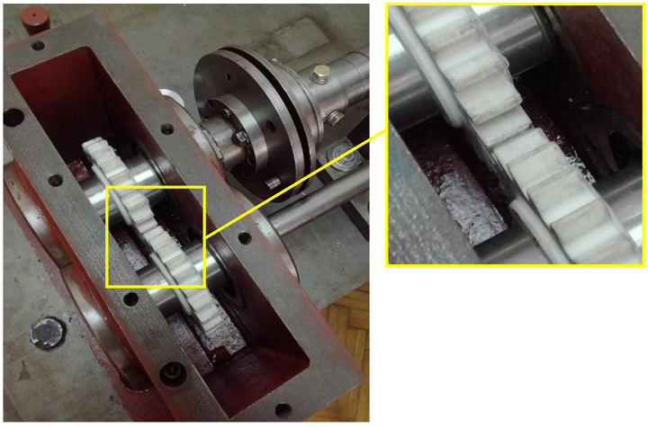
In order to cut down on material waste, and save money, laboratories will often reuse leftover metal AM powder. A trio of researchers from the I-Form Advanced Manufacturing Research Centre in Ireland published a paper, “X-ray Tomography, AFM and Nanoindentation Measurements for Recyclability Analysis of 316L Powders in 3D Printing Process,” focusing on better understanding and characterizing the mechanisms of metallic powder recycling, and evaluating ” the extent of porosity in the powder particles,” in order to optimize how many times recycled powder can actually be reused in the powder bed fusion process.

Many “risk-tolerant applications,” like in the aviation and biomedical industries, will not use recycled powder, because any part abnormalities that can be traced back to the material can be unsafe and expensive. Parts 3D printed out of recycled powder need to have mechanical properties, like hardness and effective modulus, that are comparable to those of fresh powder parts.

“In order to reuse the recycled powders in the secondary manufacturing cycles, a thorough characterization is essential to monitor the surface quality and microstructure variation of the powders affected by the laser heat within the 3D printer. Most powders are at risk of surface oxidation, clustering and porosity formation during the AM process and it’s environment [1,2],” they explained. “Our latest analysis confirms the oxidation and the population of porous particles increase in recycled powders as the major risky changes in stainless steel 316L powder [3,4].”

A common practice before reusing recycled powders is sieving, but this doesn’t lower the porosity or surface oxidation of the particles. Additionally, “the subsequent use of recycled powder” can change the final part’s mechanical strength, and not for the better.

“Here, we report our latest effort to measure the distribution of porosity formed in the recycled powders using the X-ray computing technique and correlate those analyses to the mechanical properties of the powders (hardness and effective modulus) obtained through AFM roughness measurements and nanoindentation technique,” the researchers wrote.

They used stainless steel 316L powder, and printed nine 5 x 5 x 5 mm test cubes on an EOSINT M 280 SLM 3D printer. They removed the recycled powder from the powder bed with a vacuum, and then sieved it before use; after the prints were complete, they collected sample powders again and labeled them as recycled powders.

“Both virgin and recycled powders were analyzed by number of techniques including XCT and Nanoindentation. XCT was performed by X-ray computed tomography (XCT) measurements were performed with a Xradia 500 Versa X-ray microscope with 80 KV, 7 W accelerating voltage and 2 µm threshold for 3D scan,” they wrote.

“To measure the roughness of the virgin and recycled powder particles, we performed Atomic Force Microscopy (AFM) and confocal microscopy using the Bruker Dimension ICON AFM. The average roughness was calculated using the Gwyddion software to remove the noise and applying the Median Filter on the images as a non-linear digital filtering technique.”

The researchers also ran nanoindentation on multiple powder particles, under a force of 250 µN for no more than ten seconds, in order to determine “the impact of porosity on the hardness and effective modulus of the recycled powders,” and used an optical microscope to identify pore areas on the powder.

XCT imaging of powder. (a) 3D rendered image of 900 recorded CT images, (b) region of interest, (c) internal pores in particles indicated in a 2D slice, (d) identified pores inside particles after image processing.

The XCT images were analyzed, and “a region of interest” was chosen, seen above, from which pore size and interior particle distribution were extracted.

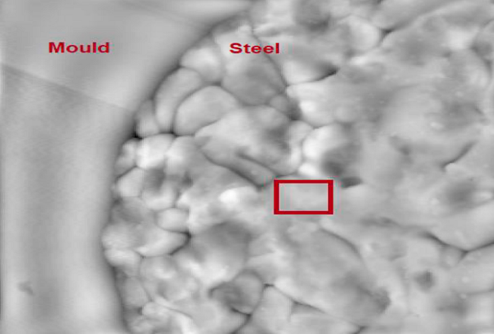
AFM image on a particle showing the boundary of mold and steel and the area where surface roughness was measured.

Software was used to process the AFM topography images of both the virgin and recycled powders, and the team applied nanoindentation on different locations of the particles, with a force of 250 µm.

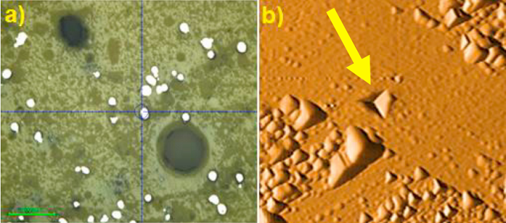
(a) powder particles placed on hardening mold for nanoindentation, and (b) an indent applied on a particle surface.

They determined that the reused powder particles had about 10% more porosity than the virgin powder, and the average roughness of the powder particle surfaces was 4.29 nm for the virgin powder and 5.49 nm for the recycled; this means that 3D printing “may increase the surface roughness of the recycled particles.” Nanoindentation measurements show that the recycled powder has an average hardness of 207 GPa, and an average effective modulus of 9.60 GPa, compared to an average of 236 GPa and 9.87 GPa for the virgin powder, “which can be correlated to porosities created beneath the surface.”

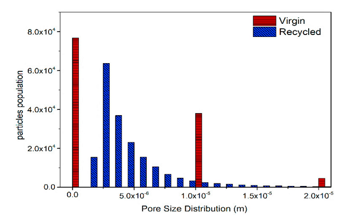
Pore size distribution in virgin and recycled powders extracted from image processing on XCT measurements.

“The pore size in recycled powders has a wider distribution compared to virgin counterpart. The main population of pore size is around 1-5 µm in virgin powder which slightly reduces to bigger size but for a smaller population. There are also bigger pores in recycled powder but with a smaller population,” they noted. “On the other hand, looking at higher pore population in virgin powder (around 10 µm size), we believe that the out-diffusion of metallic elements to the surface occurs during laser irradiation.”

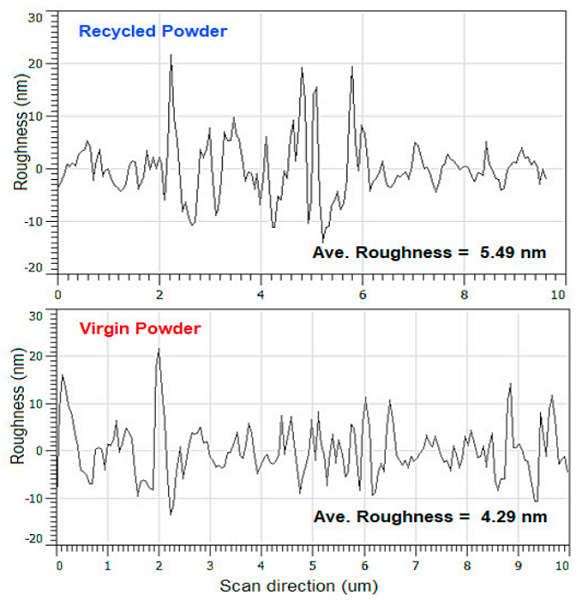
Surface roughness plots from AFM measurements on powder particles. Average roughness calculated by Gwyiddion software.

The recycled powder hardness, which is smaller than in the virgin powder, “could be attributed to higher pore density in recycled particles,” since porosity causes the powder to be “more vulnerable to the applied force resulted in smaller hardness.”

While change in grain size of the powder particles can lead to reduced mechanical properties, the team’s AFM and SEM results did not show much grain redistribution in the recycled powder. But, their nanoindentation and XCT results did find that higher powder porosity can decrease both the hardness and modulus of the particles, which “will damage the mechanical properties of the manufactured parts.”

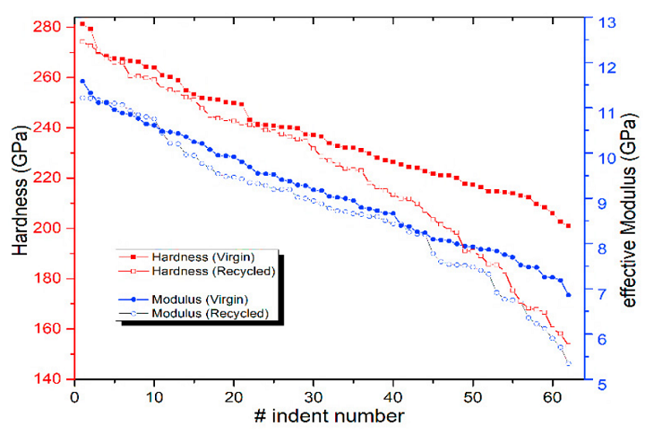
Hardness and effective modulus of fresh and virgin particles by nanoindentation.

“We have previously presented our achievement on surface and size analysis using SEM and XPS analysis. Here, we focused on pore distribution in both powders and correlated that to surface roughness, hardness and effective modulus obtained from nanoindentation analysis of the powder particles,” the researchers concluded. “The results indicate that pores population is about 10% more in recycled powders affected by the laser heat and oxygen inclusion/trap in the powder, which in turn, increases the surface roughness but reduces the hardness and modulus of the recycled powders. The pores are filled with gases (such as Argon or Oxygen) since these gases are not able to skip the melt and have a lower solubility in the melt throughout the solidification process.”

Discuss this and other 3D printing topics at 3DPrintBoard.com or share your thoughts below.

The post Ireland: Characterizing Mechanisms of Metallic 3D Printing Powder Recycling appeared first on 3DPrint.com | The Voice of 3D Printing / Additive Manufacturing.
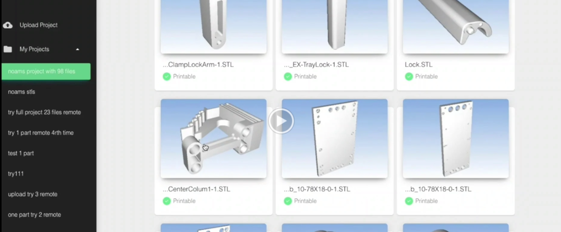
Evonik Announces Additive Pricing Analysis Software

Chemical giant and 3D printing materials company Evonik has introduced its first software for additive manufacturing (AM). The software is meant to reduce AM costs by helping users determine the proper 3D printing process depending on geometry, material and financial analysis of a part.

The technology behind the software was developed by Castor Technologies, an Israeli startup that Evonik Venture Capital invested in in October 2019. The software is framed as an auxiliary tool alongside CAD programs so that engineers can open existing CAD files, whether entire assemblies or a multitude of individual parts at once with the tool. The tool then performs an analysis of these parts and determines which are printable, how to make printable those that aren’t and the best material for printing them. It also estimates the cost and lead time and directs users to service bureaus that can print them.

The results are provided in the form of a report that includes the break-even point for AM as compared to traditional manufacturing processes. With this data, manufacturers are meant to be able to determine if and how 3D printing should be applied to the components they make.

While there are numerous methods for estimating the cost of printing a component using various AM services, a dedicated tool that determines how cost-effective using AM to fabricate a large number of parts compared to conventional methods does not yet exist on the market. Because additive is beginning to see widespread adoption and can introduce cost savings where appropriate, the tool has the potential to allow manufacturers to identify low-hanging fruit to introduce them to the technology before embarking on more involved additive projects. By giving potential users a deeper understanding of AM and its costs this could make AM much more of a viable option for many companies.

In one case study, Stanley Black and Decker used Castor’s technology to determine if any of its tooling should be produced via AM. One of the constraints was an eight-week-long lead time associated with having them made via traditional techniques. After uploading a number of tooling components, such as jigs and fixtures, Castor’s technology was able to determine high complexity, low volume parts that could be best suited for AM.

A wire lifter, for instance, was determined to be a good candidate for metal 3D printing, with an EOS M-290 system and maraging steel the system and material of choice. FIT America was selected as the service provider for the part. The software determined that the 3D printing cost for the tool would be $61 per part for 15 parts annually, compared to $120 per part using conventional manufacturing. This meant a nearly 50 percent cost reduction and the lead time was dropped from eight weeks to nine days.

“With the software, broader adoption of 3D printing at a commercial scale is now possible,” said Thomas Große-Puppendahl, head of the innovation growth field additive manufacturing at Evonik. “That will offer us better insights into customer needs and preferences in order to develop new “ready-to-use” materials.”

We don’t yet know exactly how much of Castor’s base platform is integrated into Evonik’s software; however, it is an interesting way for an additive materials manufacturer to expand to other products. In addition to its investment in Castor, Evonik provided its 20 years of additive materials expertise and ensured the accessibility of the tool to all industries. In turn, it’s possible that users might find Evonik’s polymer powders or filaments desirable for the production of their components.

The post Evonik Announces Additive Pricing Analysis Software appeared first on 3DPrint.com | The Voice of 3D Printing / Additive Manufacturing.

University of Mississippi: How to Trace 3D Printed Guns for Forensic Analysis

Parker Riley Ball is a thesis student at the University of Mississippi, exploring some complex areas regarding 3D printing, outlined in ‘Development of a Dart-Mass Spectral Database for 3D Printed Firearm Polymers, and Airborne Mercury at Three Lakes in North Mississippi.’

The research study, centered around the uses of chemometric analysis, offers an interesting focus on weapons forensics, as Ball expounds on ways to collect data on 3D printed guns and analyze the forensic information, along with creating another ‘sampling’ device (unrelated to 3D printing) for measuring high levels of mercury in Grenada, Enid, and Sardis Lakes, all tributaries in Mississippi.

Ball discusses the ‘threat of 3D printed firearms’ at length, delving into a worldwide conversation that is controversial to say the least. His point in the thesis is that there is a need to track weapons, and 3D printed guns are currently manufactured and possessed completely off the grid—along with safeguarding features such as the ability to evade metal detectors—prompting the possibility that there may be legal necessity in the future to track such weapons and their ‘manufacturers.’ Amidst exploration of DART-MS, the study of 3D printed guns, and forensic research, Ball mainly performed data analysis and interpretation, with the rest left up to fellow graduate student, Oscar Black.

DART-MS stands for direct analysis in real time – mass spectrometry and allows for the collection of ‘mass spectra under ambient conditions.’ Samples can be taken quickly, and simply. And while this is already a well-known technique for taking samples, using them for 3D printed gun forensics is a novel concept.

“With a DART ion source, a gas, He or N2, passes through a discharge chamber where an electric current is applied to generate a glow discharge, producing excited neutral chemical species called metastables,” explains Ball. “A perforated electrode removes ions from the gas stream as it travels through a second chamber. In a third chamber, the gas is then heated, and the sample is ionized by reacting with the metastables and causing desorption.”

A schematic diagram of a DART ion system (Photo Credit: Dr. Chip Cody, as used in Ball’s Thesis Study)

The researchers can use DART with a spectrometer for pinpointing and identifying the unique makeup and pattern of each sample—in this case, a 3D printed polymer used to manufacture a weapon. Ball points out that the process does not harm a forensic sample in any way, meaning that evidence can be stored and explored further, as needed later in a trial. The DART-MS ‘fingerprint mass spectra’ also makes it useful in many other law enforcement applications like drug busts and other criminal activities requiring trace analysis.

A display including 30 of the plastic samples analyzed for this study.

As the researchers expanded their analysis efforts in conjunction with the DART-MS data, they were able to categorize samples by different polymers—followed by analysis of manufacturer and color. Ball emphasizes the importance of this work for law enforcement officials in the future as they could have greater luck in identifying crimes that are gun-related, requiring further evidence for trials and convictions. Samples were taken from 50 different types of 3D printing polymers, including PLA, ABS, PETG, nylon, and more.

While the second part of the study was not related to 3D printing, Ball was engaged in creating other analytical sampling devices, with the use of a Direct Mercury Analyzer. Find out more about that study and the mechanics of measuring mercury and toxicity levels here.

“The results from this study show strong potential for the classification and identification of unknown polymer evidence as the 3D-print polymer database continues to grow,” reports Ball in the conclusion of his thesis. Chemometric analysis of mass spectral data allowed for the successful classification of various 3D-print polymer samples, and thermal desorption techniques provided an even stronger basis for this classification. It is recommended that another full study be done in the future, with a focus on modifying the parameters used in the chemometric analysis of polymers for potentially stronger separation when generating PCA plots.”

Most of the 3D printing realm is uncharted territory, and as soon as the technology hit the mainstream, designers, engineers, and a multitude of creative users around the world were left to think up an infinite amount of ways to ‘change the world’ – and get in some trouble too. Weapons of course were high on the list for enthusiasts to take a stab at, whether in creating replicas for cosplay, creating gun designs and advocating, or bikers 3D printing guns in Australia to promote crime endeavors. It’s not likely that 3D printers are going to take over as the manufacturing technique of choice, but users are curious about what they can do, and weapons enthusiasts are often very passionate about their guns and different ways to construct, and enjoy them.

What do you think of this news? Let us know your thoughts! Join the discussion of this and other 3D printing topics at 3DPrintBoard.com.

Direct analysis of 3D-Print Polymer

Thermal Desorption unit coupled to DART source at the MS inlet

[Source / Images: Development of a Dart-Mass Spectral Database for 3D Printed Firearm Polymers, and Airborne Mercury at Three Lakes in North Mississippi]

Bridgeport Research Duo Create and Analyze 3D Printed Frame for Quadrotor Drone

Quadrotor frame assembly in exploded view.

Unmanned Aerial Vehicles (UAVs), also known as drones, are agile and resilient enough to be piloted, and monitored, from remote distances. With four flying dimensions and six degrees of freedom for pitch, roll, space, and yaw, drones can be used for a wide variety of applications, such as farming, documenting 3D information about historic archaeological sites, photographymilitary and defense, acting as first responders during natural disasters and rescue operations, and 3D printing.

Multirotor drones have multiple fixed wings and have a high level of maneuverability, and are classified further based on factors like position, orientation, and number of rotors. A pair of researchers from the University of Bridgeport recently published a paper, titled “Design and Analysis of 3D Printed Quadrotor Frame,” detailing their work using 3D printing to create the frame for a quadrotor drone.

3D printed drone assembly bottom view

The abstract reads, “This research emphasizes more on 3D printing a quadrotor with ‘X’ shaped frame. We built a CAD model of drone frame using SOLIDWORKS, following that; we performed three types of finite analysis 1. Static structural, 2. Impact analysis, and 3. Modal analysis. The drone frame is simulated and analysed under various boundary conditions such as lift, drag, and thrust till the optimized results of minimum displacement, a factor of safety is achieved. We printed the frame of drone on PRUSA I3 Mk3 3D printer by using ABS-PC and carbon fiberglass materials as the filament.”

The researchers designed a CAD model of their X-framed drone in SOLIDWORKS using multiple constraints, including:

  • length of the propeller, which determines the length of an arm
  • motor rotor diameter and electronic speed controller width, which contribute to determining a drone’s arm width

Highlighted surface area is the fuselage

They designed the arms of the drone to translate force away from the fuselage, which helps electronic components maintain minimal damage if the drone has an accident or fails. The fuselage of a drone is “the eye” of its electronic components, like the receiver, power distribution board, and flight controller, and the duo designed a housing to protect the fuselage’s components in the event of a crash.

The dimensions of their drone frame, which was 3D printed on a PRUSA I3 Mk3 3D printer out of carbon fiberglass and ABS-PC, are 175.14 x 171.42 x 48.75 x 226 mm.

The researchers explained, “To perform FE analysis, the forces acting on a frame are determined, which are 1.The Weight of the frame and all the electronic components on it normal to the ground, 2. Lift force direction is a resultant between thrust and vertical take-off, towards the direction of motion, 3. Thrust generated by the propeller and motor towards the direction of motion and 4. Drag force acting in opposite direction of motion.”

Strain deformation

The researchers manually calculated and applied the forces acting on the 3D printed frame during simulation, which resulted in three plots: Von Mises stress, displacement, and strain deformation. They were able to run a sequences of cycles in SOLIDWORKS where the drone crash-landed, and gained simulation results by compiling all of the collected data. Additionally, they also completed a static structural analysis – a phenomenon called plasticity – by considering a non-linear analysis based on the materials used to make the frame and the rate of deformation, and completed a modal analysis of the 3D printed frame in order to measure the dynamic excitation caused by vibrating motors.

“A 3D printed quadrotor frame with safety factor 2.5 is attained and various finite element analysis performed on the frame are distinctly mentioned and plotted in the figures. Further, we can 3D print a 3- axis gimbal and attach it to our quadcopter for aerial photography. Also, we can upgrade them by attaching few thermal imaging sensors and gas sensors to measure radiation and air pollution at certain heights,” the researchers concluded. “This shows the main advantage of the 3D printed quadcopters and makes them stand distinct to the market-ready drones. We can customize them to make them work in any environment just by changing the printing filaments.”

3D printed drone assembly isometric view.

Co-authors of the paper are Sai Mallikarjun Parandha and Zheng Li.

Discuss this and other 3D printing topics at 3DPrintBoard.com or share your thoughts in the Facebook comments below. 

Comparing the Operational Characteristics of Plastic 3D Printed Spur Gears

Back to back gear test rig used in performed experimental research.

Spur gears, which can achieve high transmission ratio and energy efficiency, are comment elements used in the transmission of motion and high intensity power for mechanical power drives, i.e. belt drives, chain drives, and cylindrical gear drives. These power transmission elements are exposed to non-conforming operating conditions in terms of load and speed, and are also applicable at high speeds. Spur gears play a big role in mechanical engineering, and are often tested in back to back gear test rigs in order to gain data regarding the gear teeth flanks’ surface load capacity.

A group of researchers from the University of Belgrade in Serbia and the Slovak University of Technology in Bratislava published a paper, titled “The Influence of Material on the Operational Characteristics of Spur Gears Manufactured by the 3D Printing Technology,” on their efforts to test plastic 3D printed spur gears on a back to back gear test rig, in order to increase the use of the technology in manufacturing these gears.

3D printing direction of the 3D printed spur gear.

“In this paper the influence of the material type on the operational characteristics of spur gears manufactured by the 3D printing technology is analyzed, after the experimental testing performed on a back to back gear test rig, in the predefined laboratory conditions,” the researchers wrote.

“For the purposes of this paper, two types of polymeric materials were analyzed. The initial load in the form of a torque that was exposed to the spur gears was held constant, while the number of revolutions per minute of spur gears was varied. The plastic gears tested in this experiment operated in unlubricated working conditions.”

The researchers performed a comparative analysis, using commercially available PLA and ABS materials, on their impact on the 3D printed spur gears’ operating performance. The most common bulk failures in spur gears made of metal are teeth fractures and surface degradation like pitting and scuffing, but the researchers weren’t quite sure if this would be the case for their 3D printed plastic gears.

“With metallic spur gears, the load in the form of torque increases at the appropriate levels while simultaneously controlling the process of surface destruction of the gear teeth flanks,” the researchers explained.

“For the purposes of this experiment, the load in the form of a torque is fixed, that is, the initial moment of constant intensity has value 20 Nm. The torque of this intensity is insufficient to cause premature surface and volume destruction of spur gear teeth. The initially captured torque is “lost” during the wear process. The idea of this experiment was to estimate the wearing intensity for the initially captured load for two different spur gear materials.”

Worn off teeth flank surfaces of the tested PLA gears.

While back to back gear testing typically includes a constant number of revolutions of the electric motor, the frequency regulator was connected to the electric motor for this testing in order to have the ability to change the rotation. The researchers adopted a rotational speed change of 200 rpm, which was changed every ten minutes during the experiment, meaning they reached the maximum 1400 rpm after an hour of testing.

Indicators most commonly used for spur gear operational analysis include temperatures, noise and vibration levels, and the quantity and shape of wear products, and the researchers chose vibration (RMS acceleration) and temperature as the main indicators for their 3D printed ones. A thermal imaging camera was used to record the meshing temperature field of the 3D printed spur gears, while an SKF Microlog Analyzer GX collected information on the vibrations.

“Knowing the number of teeth of the tested spur gears, as well as their number of revolutions, a change in the amplitude of the vibration level is observed over time, by distinguishing the peak resulting from the meshing of the plastic spur gears,” the researchers explained.

In the first five minutes of the experiment under 200 rpm, there was hardly any vibration observed; additionally, in the first ten minutes under 200 rpm, the temperature of the PLA gears was about 20% higher than that of the ABS gears. Eventually, the 3D printed ABS spur gears endured roughly 30 minutes of work before experiencing failure in their teeth at 600 rpm, while the 3D printed PLA spur gears lasted for 90 minutes at 1400 rpm with no visible fractures, but showing “evident teeth contact surface destruction.”

Failure at the teeth roots of the tested ABS gears.

“In the interval from 5 to 15 minutes, vibrations behaviour of ABS and PLA plastic gear pairs is inverse comparing to their thermal behaviour,” the researchers wrote. “The vibrations of ABS plastic gears is higher (RMS=0,18 ms-2) than the ones made of PLA plastic (RMS=0,06 ms-2). Increasing the rotational speed from 300 up the 400 rpm, the vibration of both gear pairs significantly rises (up to RMS=0,72 ms-2). After 400 to 500 and 600 rpm, the vibration levels are declining. After 30 minutes of testing with 600 rpm, just before tooth of ABS gear pair fractured, the level of RMS accelerations was 0,3 ms-2. The vibration level of PLA plastic gear pair vary with an increase of rpm and oscillate around 0,25 ms-2. At the end of experiment (on 1400 rpm) the vibration values of PLA plastic gear pair is increasing to 0,5 ms-2, probably due to gear tooth contact surface destruction.”

Based on their findings, the researchers were able to conclude that the 3D printed PLA spur gears had better operational characteristics than the ABS ones.

Co-authors of the paper are Aleksandar Dimić, Žarko Mišković, Radivoje Mitrović, Mileta Ristivojević, Zoran Stamenić, Ján Danko, Jozef Bucha, and Tomáš Milesich.

Discuss this research and other 3D printing topics at 3DPrintBoard.com or share your thoughts below.