
Colorado-headquartered additive manufacturing material developer Elementum 3D has announced that it has been awarded patents in the U.S., Canada, and Australia for its Reactive Additive Manufacturing (RAM) technology. The RAM process aims to expand the materials library of additive manufacturing by enabling the 3D printing of previously unprintable materials. With the additive manufacturing industry at […]
Protolabs purchases GE Additive’s X-Line 3D printers for use from late summer 2020
Digital manufacturing company Protolabs plans to introduce GE Additive’s X-Line 2000R large-format 3D printers into its equipment portfolio in late summer 2020. By expanding on its metal additive manufacturing capacity, Protolabs will enable its customers to access a new method of building large-format parts with complex geometries. The build volume of the metal laser melting machine […]
Ti6A14V Titanium Alloy: Testing DMLS 3D Printed Samples Under Static Load
As 3D printing with metal continues to expand for industrial users around the world, so does the study of materials like powders, unique alloys, and a range of composites. In this study, outlining their findings in the recently published ‘Strength analysis of Ti6A14V titanium alloy produced by the use of additive manufacturing method under static load conditions,’ researchers focus on the uses of titanium alloy Ti6Al4V and comprehensive analysis of mechanical properties after printing via direct metal laser sintering (DMLS).
For many applications, the benefits of 3D printing and additive manufacturing processes overshadow more conventional methods for the creation of devices like dental implants, rocket engine components, car parts, and more. While greater affordability is key, so is the ability for many users to create parts that may never have been possible before—or even more notable, perhaps, is the option to scan older parts that have become obsolete and re-create them via 3D printing (especially helpful in applications like automotive and for the military).
Medical devices such as implants are often made from alloy due to the following advantages:
- High mechanical properties
- Low density
- Corrosion resistance
- Biocompatibility
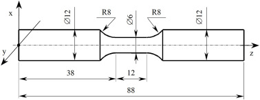
Test sample dimensions.
Heat treatment is common with the use of metals, as it improves mechanical properties. Methods such as hot isostatic pressing (HIP) are often used; however, in this study, the researchers use DMLS additive manufacturing to create the samples to be tested for viable mechanical properties.
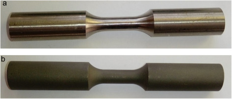
Physical form of research samples: (a) turned from a drawn bar, (b) manufactured by the additive method DMLS.
The team created samples in the form of annealed drawn bars (12mm in diameter) as well as a set created via DMLS on an EOS M280W machine, and annealed afterward.
“The printing process was characterized by the following parameters: laser power 200 W, minimum layer thickness 30 μm, scanning speed up to 7 m / s. The sample print direction was consistent with the Z axis,” explained the researchers.
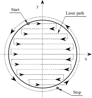
The applying scheme one layer of the sample by the DMLS method.
Strength of the first samples was found to be lower in comparison, while hardness related different values:
“The difference in results is related to the method of sample preparation by the additive technology and the external load it has been subjected to,” stated the researchers.
“Slight changes in the hardness value in the x-plane of unloaded samples indicate similar mechanical properties of the material produced by the DMLS method.”
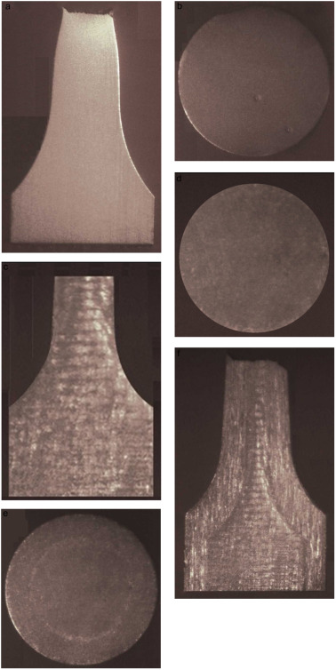
Samples for hardness tests: (a, b) samples from a drawn bar, (c, d) samples made using the DMLS method before tensile tests, (e, f) samples made using the DMLS method after tensile tests.
The team of researchers also noted that in this case, variances in hardness (between x-y and x-z) could be due to 3D printing of material grains, combined with deformations caused by the axial load.
Testing of sample DMLS macrostructures demonstrated obvious changes related to tensile load, indicating that it may also again be due to 3D printing—as well as set parameters and direction of material layers. The researchers compared macrostructures both before and after tensile loading, realizing that plastic deformations then occurred, and were plainly visible caused by the load line.
Because titanium is used in a host of 3D printing and AM processes today, this material is an ongoing source of study from use with composites, to medical devices like sternum or hip implants, printing with glass, and more.
What do you think of this news? Let us know your thoughts! Join the discussion of this and other 3D printing topics at 3DPrintBoard.com.

Macrostructure of the Ti6Al4V material resulting from the DMLS additive manufacturing method taken from: (a) samples along the Z axis, (b) sample gripping part, (c) distribution of force lines in the sample during tensile force; I – the area of significant changes in the material structure resulting from the tensile force action, II – transitional area, III – area with limited impact of tensile force.
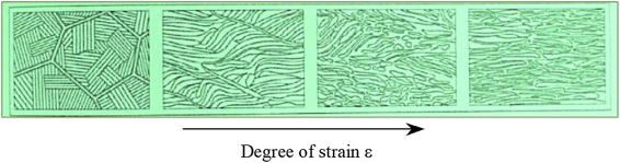
Schematic presentation of two-phase microstructure formation of two-phase α + β titanium alloy plastically deformable in the phase transition temperature range α + β → β as a function of deformation degree ε.
[Source / Images: ‘Strength analysis of Ti6A14V titanium alloy produced by the use of additive manufacturing method under static load conditions’]
The post Ti6A14V Titanium Alloy: Testing DMLS 3D Printed Samples Under Static Load appeared first on 3DPrint.com | The Voice of 3D Printing / Additive Manufacturing.
3D Printing Metal End-use Part Applications
This article describes the ideal use-cases for each process & comparison with other solutions to help you identify opportunities using 3D Hubs in your organization for metal 3d printing service.
Definition: End-use part is any good that is either sold as a product or placed in service within a company’s internal operations.
There are 6 processes to consider:
- FDM / FFF (plastics)
- SLA / DLP (plastics)
- SLS / MJF (plastics)
- SLM / DMLS (metals)
- Metal FFF (metals)
- Binder Jetting (metals)
In part 1 we talked about plastic parts, in part 2 we discuss only metals.
4. SLM/DMLS
Selective Laser Melting (SLM) and Direct Metal Laser Sintering (DMLS) are metal powder bed fusion 3D Hubs printing processes that are most commonly used today as they are especially suitable for high-end applications since they offer advanced material properties and superb design freedom.
While both utilize high laser power to bond together metal powder particles to form a part– layer-by-layer, SLM will achieve a full melt, while — due to the very high temperatures — DMLS will cause the metal particles to fuse together at a molecular level.
The majority of metal alloys are compatible with the DMLS method, wherein SLM, only certain (pure) metal materials may be used.
Still, the differences between these two 3D Hubs printing technologies are so slim; they can be treated as the same for designing purposes.
In this section, we will take a closer look at the technical characteristics, manufacturing process, and the limitations and benefits of these two, very similar techniques.
How it works: SLM/DMLS 3D Hubs printing process basic steps:
- First, the build chamber is filled with inert gas then heated to the optimum print temperature.
- A thin layer (typically 50 μm) of metal powder is spread over the build platform.
- Next, the laser scans the cross-section of the part, selectively bonding the metal particles.
- Thus, the build platform moves down a layer when the entire area is scanned, and the process repeats until the build is complete.
- After the printing process is complete, the build must first cool down before the loose powder is extracted.
This step is only the beginning of the SLM/DMLS 3D printing manufacturing process. Once the print is complete, several compulsory and/or optional post-processing steps are also required before the parts will be ready for use.
Compulsory post-processing steps include
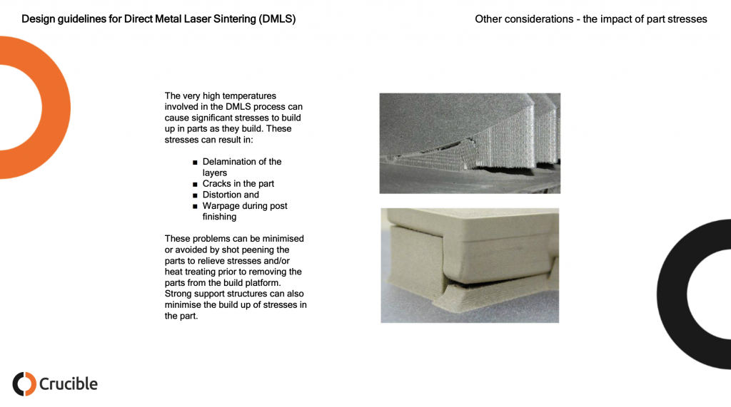
- Stress relief: Before continuing with any other operation, the internal stresses that develop during printing, due to the very high processing temperatures, need to be relieved through a thermal cycle.
- Removal of the parts: In SLM/DMLS the parts are welded onto the build platform and EDM wire cutting or a band saw are used.
- Removal of the support: To mitigate the distortion and warping that occurs during printing, support in SLM/DMLS is required. Support is CNC machined or removed manually.
Additional post-processing steps are often required to meet engineering specifications that may include:
- CNC machining: When tolerances are tighter than the standard ± 0.1 mm that’s required, machining is employed as a finishing step. Only the slight material is removed this way.
- Heat treatments: Hot Isostatic Pressing (HIP) or heat treatments can be used to improve the material properties of the part.
- Smoothing/Polishing: Certain application requires a smoother surface than the standard RA 10 μm of as-printed SLM/DMLS. CNC machining and Vibro, chemical, or manual polishing are available solutions.
How it works: Laser source bonds metal powder particles
Strengths:
- Geometric freedom
- High accuracy & fine details
- High-performance materials
Materials:
- Stainless Steel
- Aluminum
- Titanium
- Superalloys
Use case #1 – Optimized brackets
DMLS / SLM is used to create lightweight parts through advanced CAD processes, such as topology optimization. They are of particular interest in the automotive and aerospace industries.
Use case #2 – Internal geometries
A far more common use of DMLS / SLM is the creation of parts with internal channels. These find applications in the manufacturing industry (for example injection molding tooling with internal channels for cooling) or for heat exchangers.
Pro tip: Make sure that no support structures are needed to manufacture the internal channels, as they will be impossible to remove.
5. Metal FFF: What is metal extrusion?
Metal Extrusion is a low-cost metal 3D printing process alternative that is most suitable for prototyping purposes or for one-off custom parts.
It is a variation of the classic FDM method for plastics. In 2018, the first Metal Extrusion 3D printers were released also known as an Atomic Diffusion Additive Manufacturing (ADAM) and Bound Metal Deposition (BMD).
A part is built layer-by-layer, like FDM, by extruding material through a nozzle, but the material is not plastic, unlike FDM but is a metal powder held together with a polymer binder. The result of the printing step is a “green” part that needs to be sintered and de-bonded to become fully metal.
Here, we examine the characteristics and key limitations and benefits of this additive process to help you understand how you can use it more effectively.
How does metal extrusion work?
Metal Extrusion consists of a three-stage process involving a printing stage, a de-binding stage, and a sintering stage.
The Printing Stage…
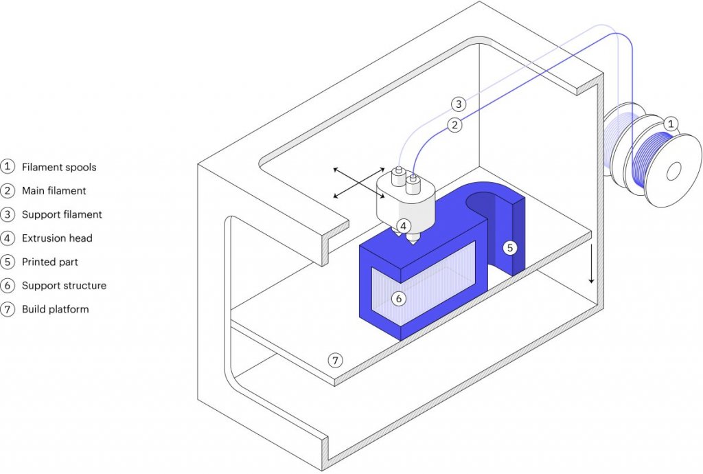
- Raw material in a rod or filament form, which basically consists of metal particles that are bound together by wax and/or polymer.
- This filament or rod is extruded through a heated nozzle and then deposited– layer-by-layer to build a designed part based on the CAD model.
- While, if necessary, support structures are built. The interface between the part and the support is printed with ceramic support material that can easily be removed later manually.
When printing is complete, the “green” resulting part must be post-processed using similar steps like Binder Jetting, in order to become metal. The “green” part is washed first for several hours in a solution to remove almost all of the binders. Then it is sintered inside a furnace so that the metal particles are bonded together to form the fully-metal part.
During the sintering process, the dimensions of the parts are reduced by about 20 percent. to compensate for this, the parts are printed larger. Like the Binder Jetting process, the shrinkage isn’t homogenous, meaning that trial and error will be required to get accurate results for particular designs.
How it works: Metal/binder is extruded through a nozzle to print the part, which is then thermally sintered.
Strengths:
- Does not require industrial facilities
- Based on MIM
- Complex metal parts
Materials:
- Stainless steel
- Tool steel
Main use: For internal operations
An alternative to CNC, Sand casting
Quantity: 1-50 parts
Use case #1 – CNC part replacements
Metal Extrusion is excellent for functional CNC prototyping and small productions of metal parts that would otherwise require a 5-axis CNC machining to produce.
6. Metal Binder Jetting
Metal Binder Jetting is increasing in popularity rapidly. What makes it especially suitable for small to medium production runs, is its unique characteristics.
In this section, we will dive deeper within the steps used in the Binder Jetting to learn the basic characteristics of metal parts production.
What is Metal Binder Jetting?
Metal Binder Jetting is a process of building parts by placing a binding agent on a slightly thin layer of powder in through inkjet nozzles. Originally, it was used to develop full-color models and prototypes from sandstone. A variation of the technique is becoming more popular lately, because of its batch production capabilities.
In metal Binder Jetting printing, the printing step is done at room temperature, which means the thermal effects, such as, internal stresses and warping aren’t a problem, like in SLM/ DMLS, and therefore, supports are not needed. To create a fully metal part, an additional post-processing step is required.
How does Metal Binder Jetting work?
Metal Binder Jetting involves two-stages; a printing stage and a post-processing stage.
The printing process works like this…
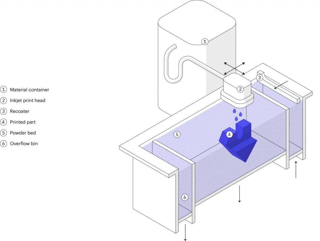
- A thin layer (typically 50 μm) of metal powder is spread out over the build platform.
- A carriage that has inkjet nozzles will pass over the bed while selectively depositing binding agent droplets of wax and polymer to bond together the metal powder particles.
- When done, the build platform will move down, then the process will repeat until the entire build is complete.
The result of this printing process is a part of the “green” state. To create fully metal parts and remove the binding agent, a post-processing step is necessary.
This post-processing stage requires two variations: Infiltration and Sintering.
How it works: Binder is jetted onto metal powder particles to create the part, which is then thermally sintered
Strengths:
- Great design freedom
- Based on MIM
- Batch production
Materials:
- Stainless steel
- Tool steel
Main use: Low-run metal production
An alternative to Metal Injection Molding, Die casting
Use case – Low-run production
Binder Jetting is the only metal 3D printing technology today that can be used cost-effectively for low-to-medium batch production of metal parts that are smaller than a tennis ball.
Why engineers use 3D Hubs for 3D printing
Instant quoting & DFM feedback
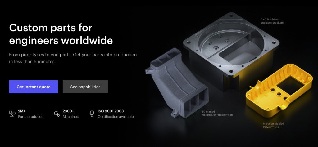
Build and edit your quote online. Review your parts for manufacturability and assess the cost of different materials, processes and lead times for your project in real-time. Explore our 3d printing service for every type of additive manufacturing project.
Readily available capacity
Benefit from our network of 250 manufacturing partners to access instantly available capacity. Our manufacturing partners are both local and overseas.
Quality & reliability
Dedicated 3D Hubs team to ensure your parts consistently meet your quality expectations. We also offer phone, email and chat support for any concerns or questions you may have.
The post 3D Printing Metal End-use Part Applications appeared first on 3DPrint.com | The Voice of 3D Printing / Additive Manufacturing.
Farsoon successfully adapts H13 tool steel for DMLS additive manufacturing
Farsoon Technologies, a Chinese metal and polymer 3D printer manufacturer, has devised a method to produce H13 tool steel parts by laser sintering. After parameter optimization tests, the company has managed to 3D print H13 with properties comparable to those made by forging. In collaboration with American tooling production company Next Chapter Manufacturing, Farsoon has […]
Researchers Design Fully Articulated 3D Printed Finger Prosthesis
Silicone cosmetic restoration of middle and ring finger with skin tone match to subject.
Despite the wide range of prosthetics available today, those with partial hand loss are often left out in the cold—and with a disability that often proves to be extremely challenging due to a significant loss of dexterity. Researchers from University of Colorado and Rice University aim to change that with a new design for a finger prosthesis that is fully articulated, featuring a self-contained actuator. The project and subsequent testing are detailed in their recently published paper, ‘Design and evaluation of a distally actuated powered finger prosthesis with self-contained transmission for individuals with partial hand loss.’
Using direct laser metal sintering (DMLS), the research team created a gear transmission for the medial phalanx portion of the finger. The transmission then connects with the DC motor, allowing torque transmission across the PIP joint. This new design features an automated device that is like the index finger size of a female in the 25-50th percentile. While this is an average size, in the future sizing may be possible for other amputees. For proper balance and ‘perception of the prosthesis as an external load worn on the residual limb,’ the scientists designed it with a weight like a human finger.
“The finger phalanges and underactuation mechanism form a six-bar linkage and is essentially a superposition of two four-bar linkages commonly used to underactuate two-phalanx commercial and research devices,” state the researchers. “The linkage system couples the motion of each IP joint to provide a flexion trajectory suitable for a variety of grasps used in ADL.
Testing was centered around evaluating force and flexion of the fingertips, using an Escon 24/2 controller from Maxon Motors powered at 12 V, and a Futek LSB200 load cell powered at 24 V for connecting with the fingertip at varying angles. The researchers also used a Quanser Q8-USB data acquisition board using MATLAB/Simulink to collect the following:
- Collected load cell force
- Motor current draw
- Voltage
In evaluating force of the prosthetic finger, the researchers position the load cell within contact of the fingertip, while the controller powered the motor—driving the finger to the load cell. After that the researchers set up the following steps:
- The motor was powered for .5 seconds after detecting the impulse load.
- The holding force was recorded.
- The load cell was moved to contact the fingertip to measure the flexion speed.
- Flexion speed was determined by ‘dividing the time the finger took to contact the load cell from its fully extended position by the angular displacement of the finger.’
The researchers repeated the trials 15 times. As they began evaluating individual gear stages, the team realized further examination would be needed to assess contributions of the face gear pair to transmission efficiency. Mechanics of the fingers will require more validation too, along with further fatigue testing.

Fitting of Vincent finger onto patient. Note location of battery and electrodes on forearm.
“Ongoing work on the powered finger has resulted in a more compact and higher reduction power transmission and future work will include a closer evaluation of the transmission efficiencies to determine the benefit of using face gears and the changes made to the structure of planetary gear stages,” concluded the researchers. “Alternative gearings that increase the overall reduction of the transmission while decreasing the number of gear stages necessary is of interest, in addition to a more thorough examination of the gear polishing process.
“Work will also include refinements to the residual limb attachment that better accommodates individuals with amputations distal to the MCP, as well as improvements to the robustness and anatomical motion of the kinematic link bar system. Upcoming iterations of the finger will also include improvements to its performance in opposition and safety mechanisms to protect the components in extreme or unexpected loading cases.”
3D printing has earned an honorable niche in the world of prosthetics, undeniably changing the lives of many, from prosthetics that help veterans, to amphibious limbs, to prosthetic breasts for mastectomy patients. What do you think of this news? Let us know your thoughts; join the discussion of this and other 3D printing topics at 3DPrintBoard.com.
Exploded view of medial phalanx gear transmission. Parts outlined in rectangles are the different lamina. Left and right inner laminae contain planetary stages and enclose spur/bevel gear stages housed in the central lamina. Outer laminae connect to proximal phalanx and enclose carrier pieces. Output of gear transmission connects to distal phalanx.
Rendering of the steel components of the powered finger with kinematic link bar system outlined. Dashed lines indicate that the bracket containing the links has been raised to show orientation. Bracket is grounded to proximal phalanx with two set screws at locations indicated by arrows. The hollowed plastic shells that enclose the entire finger mechanism are not shown for clarity.
[Source / Images: Design and evaluation of a distally actuated powered finger prosthesis with self-contained transmission for individuals with partial hand loss]
Protolabs launches service for 3D printed copper parts
Protolabs, an award-winning on-demand manufacturing provider, has launched a copper 3D printing service, where it is now offering copper parts produced by additive manufacturing as well as CNC machining. By providing this service, Protolabs is looking to fill a gap in market for copper part suppliers, which are often prototyped or produced using CNC machining. […]
Design Guidelines for Direct Metal Laser Sintering, Selective Laser Melting, Laser Powder Bed Fusion
Perchance I came across an excellent document on the design guidelines for Direct Metal Laser Sintering, also called DMLS, Selective Laser Melting, SLM, Laser Powder Bed Fusion and referred to as metal 3D printing. This document was made by UK based design consultancy Crucible Design. Crucible Design was founded in 1990 by Hugh Raymond and Mike Ayre who for the past 28 years have been tackling tough, complex advanced engineering and design projects. Whether working on cost reduction projects or bringing completely new products to market Crucible Design has carefully built up its reputation over the decades. I was so impressed with Crucible’s design guidelines for metal printing document that I asked CEO Mike Ayre if we could republish it here. I also asked him how he came to make it.
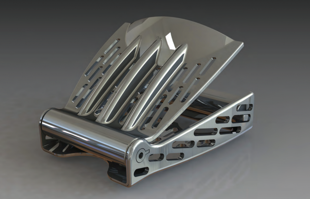
The main reason behind my work with metal 3D printing was the SAVING project, which was run by a consortium in 2011 and 2012. The consortium consisted of Exeter University, ourselves, Plunkett Associates, Delcam, EOS and Simpleware. The point of the project was to find ways to use additive manufacturing to reduce energy use. As the processes themselves are so energy intensive, we soon concluded that the only way to achieve the objective was through the use of the parts, not their manufacture. This is where the airline buckle project came from – reducing the weight of the plane to minimise fuel wastage.
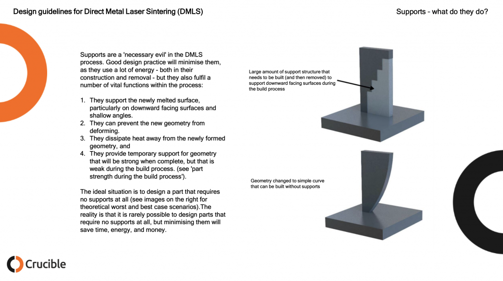
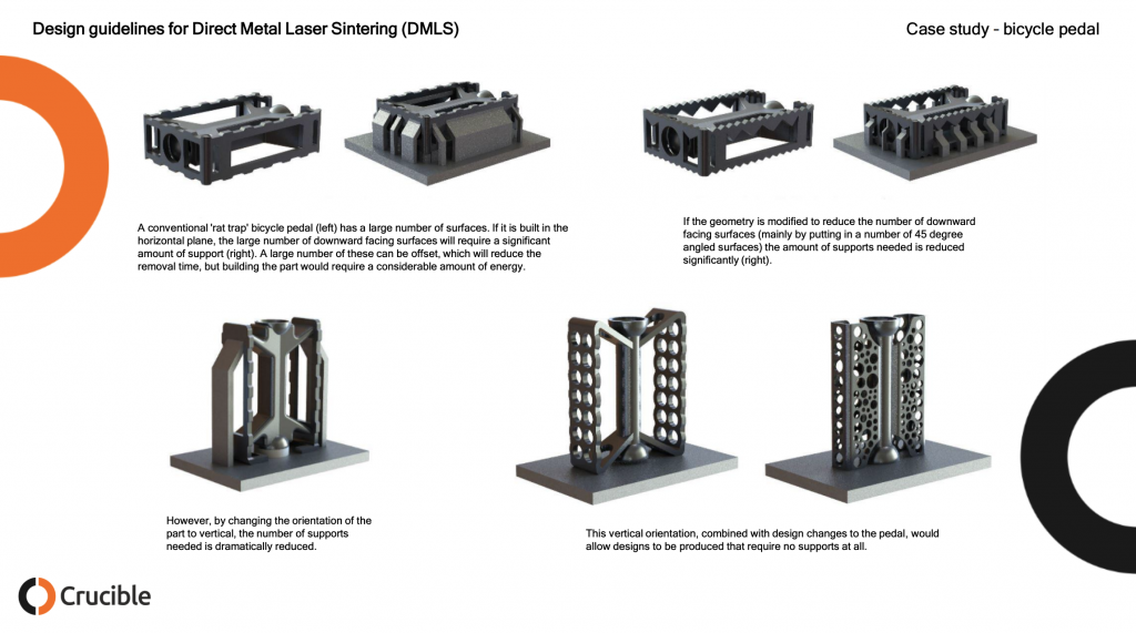
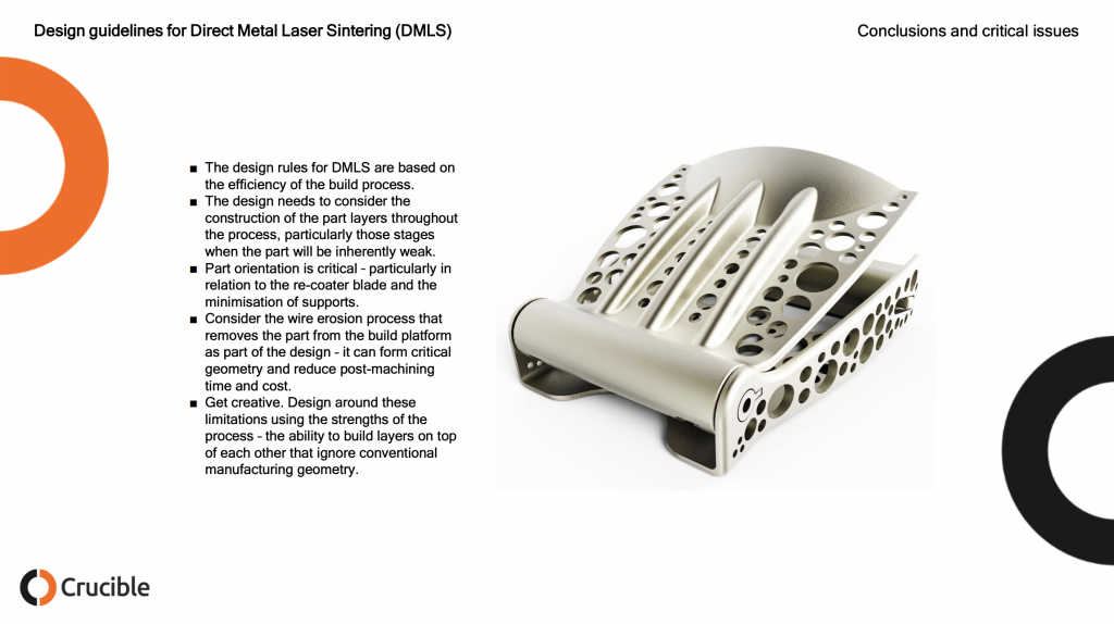
The main problem with metal 3D printing was the same as all design approaches to additive manufacture: early promoters pushed the idea that there were no design limitations, and we ‘were only limited by our imagination’. In fact, this proved to be completely wrong, with 3D printing just having different limitations to conventional methods. In terms of metal printing, the main one is the need to machine out the support structures that are required for any downward facing horizontal surface (the kind of thing that can be washed away using and FDM machine). This requires any efficient design to adopt almost medieval approaches to design, with pointed arches and sloping surfaces that can be built without supports.
Why did you make the guide?
The main reason for making the guide was to inform designers of some of the basic rules and encourage a more creative approach to the use of 3D metal printing and additive manufacture in general. It has been good to see that, since it was written, there is a lot more discussion about appropriate design methods for additive manufacture.
Now the guide was published in 2015 which is eons in 3D printing land. However, the same process limitations and design rules persist. I’ve made design guidelines and design rules documents before and was super impressed with how clear and concise this one was. I think that this is a very valuable resource to people in metal printing today either to learn about designing for metal 3D printing or to use as a teaching aid to help others. If you’re in a design project with a customer then this is also super helpful in trying to let them see that “complexity is free only in dreams.” I am absolutely certain that these images will be spread far and wide, do please credit Crucible Design for their hard work, be mindful that these images are still their copyright and reach out to them should you need any 3D printing design services done. The images below are all Crucible’s the comments are mine.
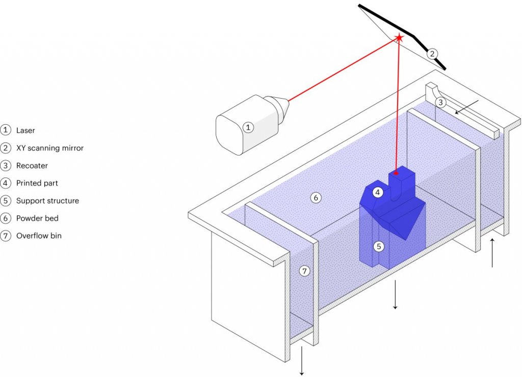
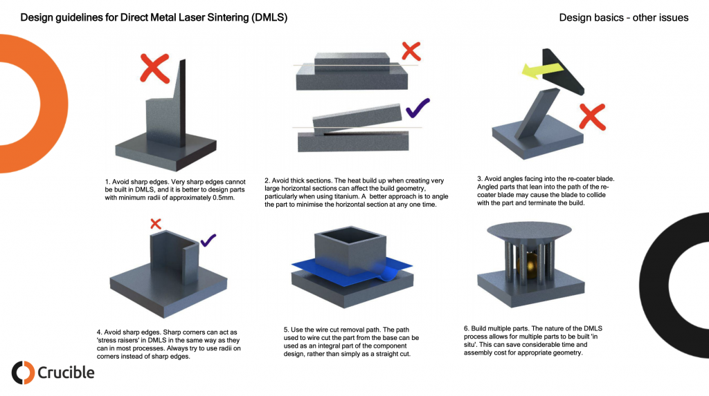
Below we can see how DMLS works. A layer of metal powder around 40 micron in diameter and round but not too round is deposited on a build platform and spread out by a recoater. This may be a roller or a knife blade type of recoater. The laser fuses the powder that will make up your part leaving the other loose powder behind. To keep your part from ripping itself apart due to thermal stress supports are needed which will be removed later.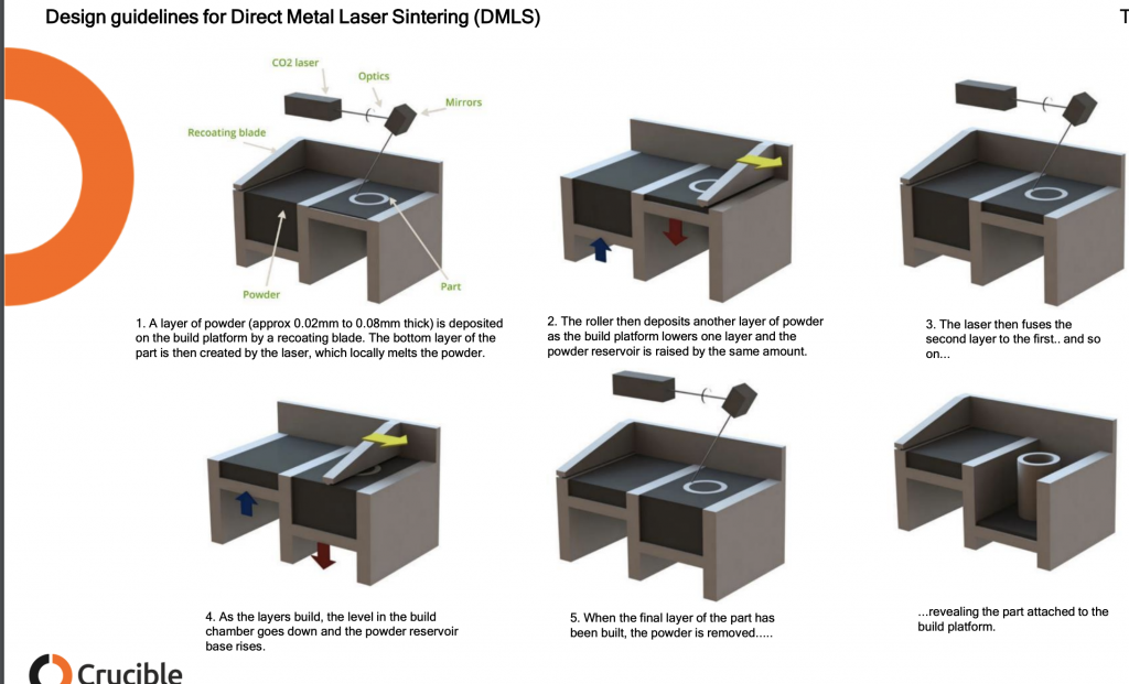
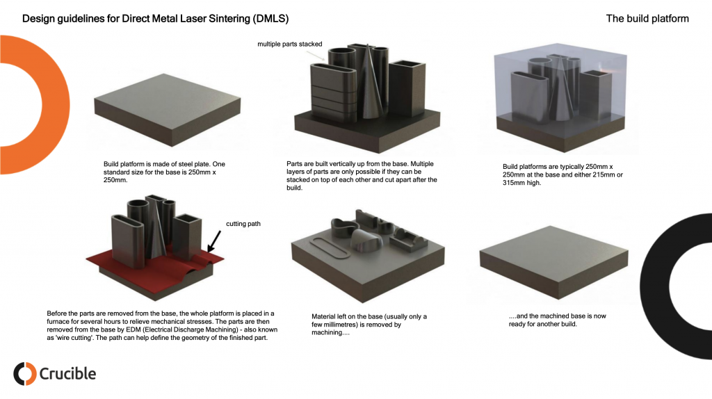
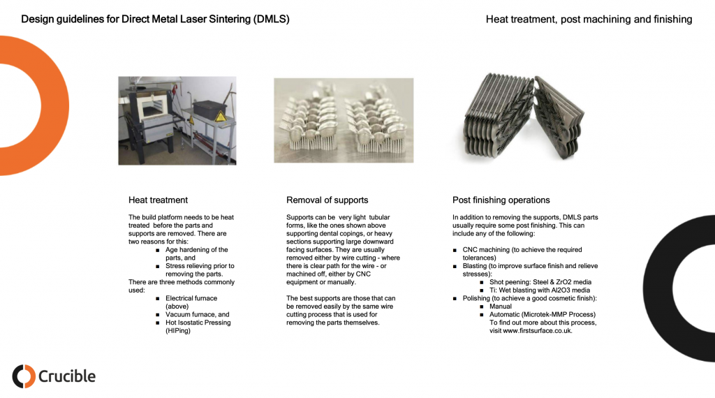
While the build plates below seem very full and indeed parts can be stacked efficiently often single parts are built at a time and parts are not stacked. This has to do with the fact that much of the industry is not yet optimized for production and worry that layer skips or recoater bumps and other errors will disrupt a week long build four days in. Note the high amount of manual labor required here. Every one of the bottom column steps will require a person lifting a few kilos at least to a new station or machine. Not shown here is the manual removal of loose powder. In addition to EDM CNC or tumbling (sometimes for a week or more) may be used as well. Depending on the needed Ra and finish of the part many steps will be required including quality control steps such as CT scanning the part to make sure that there are no internal tears or holes.
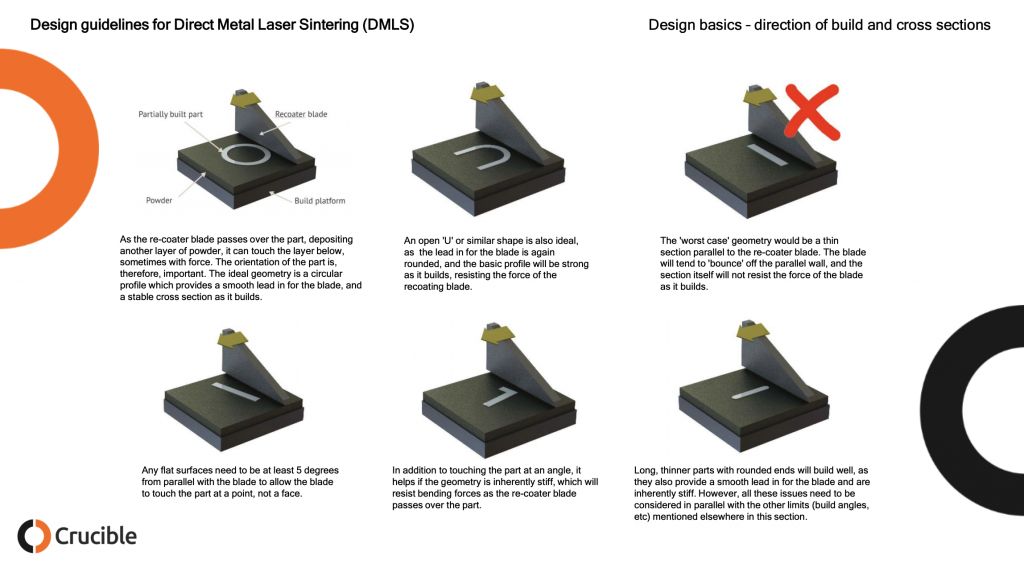
Parts built in such a way as to make it easy for the recoater to hit them with any force and its best to mitigate part strength in such a way that when that does happen your build doesn’t fail.
Overhanging surfaces in DMLS can be very rough indeed this may require a lot of post-processing. Occluded holes could trap material inside or require supports that can not be removed while large holes could cause parts to tear themselves asunder.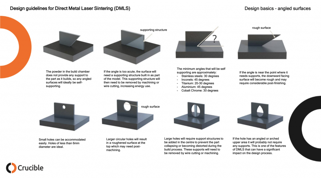
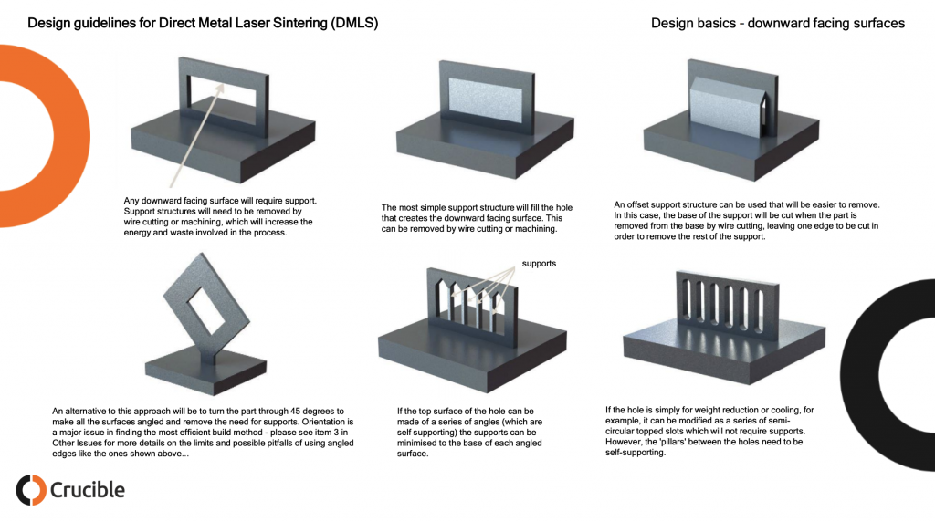
Another thing to consider below is, can the final part withstand the removal of the suports? 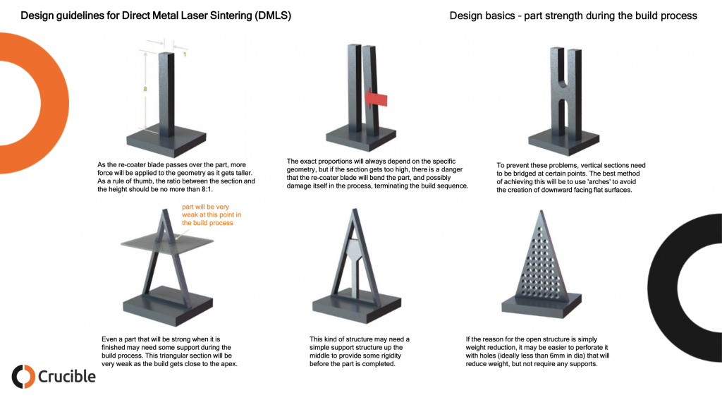
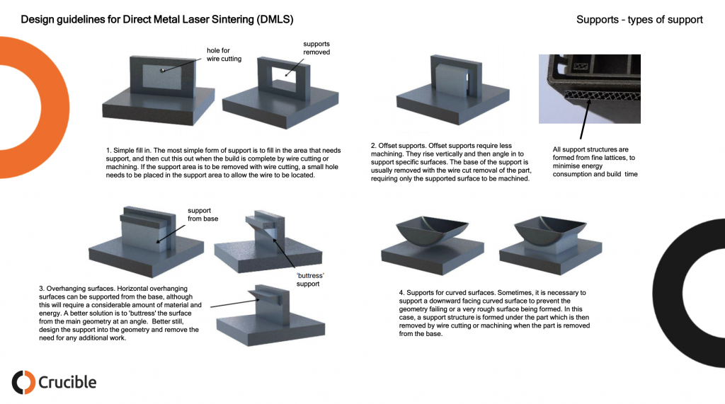
Designing supports that are easy to remove saves a lot of labor. Often a staff member with a flex or circular saw will be cutting away supports. Making sure that this person could do this without damaging the part reduces time and the need to rebuild a part.
Below are some simple support strategies for DMLS. Often a person with decades of experience can do this in their head. While there are some tools that build supports, support strategies for parts still require a lot of experience and thought. Often it will take days for a build and post processing to complete. If you then after four days find out your part has failed then you have to do another iteration. When making completely new geometries several part failures are common. If you have a type of geometry understood (acetabular cups, teeth) then you can print millions of them in many variations.
3D Printing News Briefs: January 26, 2019
We’re starting with business first in this edition of 3D Printing News Briefs, and then moving on to design software and 3D printing materials. Mimaki USA is getting ready for the grand opening of its LA Technology Center next month, and a Sartomer executive has been elected to the RadTech board of directors. A startup will soon be offering a new cryptotoken for additive manufacturing, and the 3D Printing Association will cease operations. A simplified Blender user interface will make 3D printing easier, and Protolabs is introducing some new materials for its DMLS 3D printing.
Mimaki USA Opening Los Angeles Technology Center
![]() Not long after Japanese company Mimaki Engineering launched its first full-color inkjet printer in 1996, it established Mimaki USA, an operating entity that manufactures digital printing and cutting products around the world. Mimaki USA began preparing to enter the 3D printing market in 2015, and installed its first 3DUJ-553 3D printer in the Americas last winter. Now, it’s preparing for the grand opening of its Los Angeles Technology Center next month.
Not long after Japanese company Mimaki Engineering launched its first full-color inkjet printer in 1996, it established Mimaki USA, an operating entity that manufactures digital printing and cutting products around the world. Mimaki USA began preparing to enter the 3D printing market in 2015, and installed its first 3DUJ-553 3D printer in the Americas last winter. Now, it’s preparing for the grand opening of its Los Angeles Technology Center next month.
The event will take place on Friday, February 22nd from 10 am to 4 pm at the new technology center, located at 150 West Walnut Street, Suite 100, in Gardena, California. Attendees will have the chance to meet the company’s industry experts, along with Mimaki Engineering Chairman Akira Ikeda, Mimaki USA President Naoya Kawagoshi, and the regional sales managers from all seven technology centers. Live demonstrations of the company’s printers and cutters will commence after lunch, and attendees will also enjoy tours of the center and a traditional Japanese Kagami Biraki ceremony.
Sartomer’s Jeffrey Klang Elected to RadTech Board
 Sartomer, an Arkema Inc. business unit and developer of UV/EB curing technology products, has announced that Jeffrey Klang, its global R&D Directer – 3D Printing for Sartomer, has been elected to the board of directors for RadTech, a nonprofit trade association that promotes the use and development of UV and EB processing technologies. Sartomer is part of Arkema’s commercial platform dedicated to additive manufacturing, and Klang, an inventor with over 20 US patents who was previously the manager for Sartomer’s Coatings Platform R&D, has played an important role in helping the company develop and commercialize many of its oligomers and monomers.
“Jeff’s strong leadership of Sartomer’s innovation and R&D initiatives supports the evolving needs of UV and EB processors in diverse industries, such as 3D printing, coatings, graphic arts, adhesives, sealants, elastomers and electronics. His deep understanding of UV/EB technologies, markets and regulatory requirements will make him an asset to RadTech’s board of directors,” said Kenny Messer, the President of Sartomer Americas.
erecoin Startup to Offer New Cryptocurrency for Additive Manufacturing
 A startup called erecoin, which is a product of CAE lab GmbH, is on a mission to change the world of 3D printing by combining the benefits of blockchain with future demands of the ever expanding AM community. After a year of preparation, erecoin has completed the registration of its ICO (Initial Coin Offering), and people can begin purchasing its new cryptotoken on the Ethereum public trading infrastructure starting February 18, 2019.
“We are glad and proud that we, as a young startup, managed to master the necessary steps for a functioning utility token,” said erecoin Co-Founder Konstantin Steinmüller. “At the same time we are curious to see how the community supports our crowdfunding.”
Steinmüller told fellow co-founder Jürgen Kleinfelder about a concrete 3D prototype optimization project that CAE-lab was working on, which is how the idea to combine blockchain and 3D printing came about. The startup’s goal is to get rid of many of the uncertainties in the AM process chain, and blockchain can be used to conclude smart contracts to solve legal and technical questions in the industry. Because data exchange is integrated into the blockchain, a secure and efficient relationship of trust is created between the parties in the chain. Time will only tell if erecoin can achieve its goal and help accelerate additive manufacturing or if it is just hopeful hype or an inefficient way to do something no one needs.
3D Printing Association Closes
![]() The 3D Printing Association (3DPA) is the member-funded, global trade association for the 3D printing industry in Europe. In 2015, the 3DPA moved its base of operations to The Hague in order to develop an independent professional B2B platform for European AM industries. As the 3D printing landscape continues to grow and mature, the association has decided to permanently terminate its operations beginning February 1st, 2019. But this isn’t necessarily bad news – in fact, 3DPA is glad that CECIMO, the European Association of the Machine Tool Industries and related Manufacturing Technologies, has been able to set itself up as a leading 3D printing advocate in Europe.
The 3D Printing Association (3DPA) is the member-funded, global trade association for the 3D printing industry in Europe. In 2015, the 3DPA moved its base of operations to The Hague in order to develop an independent professional B2B platform for European AM industries. As the 3D printing landscape continues to grow and mature, the association has decided to permanently terminate its operations beginning February 1st, 2019. But this isn’t necessarily bad news – in fact, 3DPA is glad that CECIMO, the European Association of the Machine Tool Industries and related Manufacturing Technologies, has been able to set itself up as a leading 3D printing advocate in Europe.
“3DPA’s goal, derived from an online survey and a business summit at the beginning of 2015, was to provide an independent B2B platform for standardisation, education and industry advocacy. Although there are still important steps to be taken to reaching full maturity, meanwhile the landscape has become less fragmented and volatile, and additive manufacturing has been embraced as strategic pillar by well-established umbrella organisations in sectors like manufacturing, automotive, aerospace and medical appliances,” said 3DPA’s Managing Director Jules Lejeune.
“CECIMO for example, is the long standing European Association of the Machine Tool Industries and related Manufacturing Technologies. It represents some 350 leading AM companies that play a significant role in a wide variety of critical sections of the AM value chain – from the supply of all different types of raw materials for additive manufacturing and the development of software, to machine manufacturing and post-processing. In recent years, it has successfully claimed a leading role in bringing relevant topics to the regulatory agenda in Brussels.”
Simplified Blender User Interface
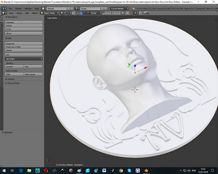 While the free 3D design and modeling software application Blender is very handy, it’s only helpful if you’re able to learn how to use it, and by some accounts, that is not an easy feat. But, now there’s a new version of Blender that includes a simplified user interface (UI) that’s so easy, even kids as young as 10 years old can figure out how to work it. FluidDesigner has used a new Blender 2.79 feature called Application Templates, which makes it possible to add a library of parametric smart objects and reduce the menu structure and interface.
“Application Templates allows for the simplification of the UI but with the whole power of Blender in the background. You can access nearly all of Blender commands from the Spacebar or by switching panels. Another way to look at it is that it is an Application Template is an almighty Add-On,” Paul Summers from FluidDesigner said in an email.
“All objects are either Nurbs or Bezier (2D) Curves for ease of editing. Nurbs objects in particular can be joined together to create personalised jewellery or artwork quickly and simply.
“There is no need to go to the trouble of joining objects using Boolean modifiers, instead you simply overlap Nurbs objects and then run the *.obj file through Netfabb Basic to repair any issues created with Blender objects. With its much simplified interface, created by Andrew Peel, FluidDesigner for 3D Printing with its parametric smart objects (Nurbs curves) is suitable for even the novice user. The current version runs under Blender 2.79 and can be accessed from the File menu.”
Protolabs Adds New DMLS Materials
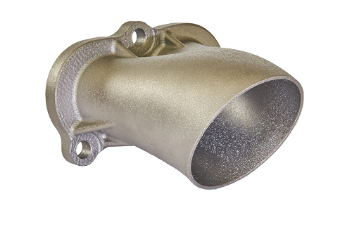 Protolabs, a digital manufacturing source for custom prototypes and low-volume production parts, has announced that it is enhancing its direct metal laser sintering (DMLS) offering with two new materials. Nickel-based Inconel 718 is a heat- and corrosion-resistant alloy with high creep, fatigue, rupture, and tensile strength, is able to create a thick, stable, passivating oxide layer at high temperatures, which protects it from attack – making it an ideal material for aerospace and other heavy industries for manufacturing gas turbine parts, jet engines, and rocket engine components.
Maraging Steel 1.2709 is a pre-alloyed, ultra-high strength steel in the form of fine powder. It’s easy to heat treat with a simple thermal age-hardening process, and offers high hardness and high-temperature resistance, which makes it perfect for high performance industrial and engineering parts and tooling applications. These two new Protolabs materials additions help reinforce the company’s enduring reputation as one that can offer an impressive range of metals.
Discuss these stories and other 3D printing topics at 3DPrintBoard.com or share your thoughts in the Facebook comments below.
Acoustics Play a Role in Determining 3D Print Quality
 Metal 3D printing is constantly under study to improve its quality and repeatability. A new research paper focuses on direct metal laser sintering (DMLS), also known as selective laser melting (SLM) and Powder Bed Fusion for Metal. DMLS still has its shortcomings, which include delamination between base plates and inaccuracy among various orientations. The paper, entitled “Characterization of acoustic signals during a direct metal laser sintering process,” points out that sintered parts tend to still be relatively large, soft and porous, hampering their widespread use, so improving part quality and repetability is crucial, especially for industries like aerospace and medicine.
The researchers look at acoustic signal processing as a way to monitor the build quality of a 3D printed part while in progress.
“This paper reports the relationship between acoustic signals, laser power as well as its laser scanning speed,” the researchers state. “The variety of acoustic signal power spectrum density (PSD) is presented and then the mechanism of acoustic signal formation is elaborated. A good mapping between acoustic signals and laser parameters has been found during the DMLS process. This lays a good foundation for monitoring the process and quality by acoustic signal and will enhance the part quality during the powder-based laser sintering and melting processes in the future.”
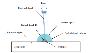 Several methods of in-process monitoring exist, such as optical, thermal, ultrasound and acoustic signals. Each has its drawbacks, but acoustic signals have been found to be an effective method as long as they are not disrupted by environmental noise. In this study, acoustic signals generated during the DMLS process were sampled and utilized for online monitoring.
Acoustic signals in a DMLS process are generated by several factors, mostly by the vibration from the friction of flow medium with liquid or solid matter, as well as flow motion. The signals in this study were sampled by an electret condenser microphone and processed with MATLAB 2015b.
The results of the experiment showed that there was a good correlation between the laser frequency and laser power as well as the laser scanning speed and acoustic signals.
“Through the investigation of the acoustic signal, information on the laser scanning characteristics can be extracted,” the researchers explain. “The second frequency peak is more promising for detecting the laser scanning attributes.”
 The study showed that there was a good mapping between the acoustic signals and laser scanning status as well as the resulting laser sintering quality. These results, according to the researchers, will lead to future monitoring techniques for DMLS and provide a strong foundation for real-time control of metal printing processes.
“Future studies will be carried out on part qualities such as surface roughness, porosity, density and composition of the powder mixture interpreted via acoustic signals,” they conclude. “Defects can be predicted automatically for quality monitoring and feedback control.”
Studies like this one are important steps toward understanding what is happening during the metal 3D printing process, so that defects can be caught and avoided. Metal 3D printing is far from a perfect process, but the more technology is applied to understanding it, the more effective it will be.
Authors of the paper include Dongsen Ye, Yingjie Zhang, Kunpeng Zhu, Geok Soon Hong and Jerry Fuh Ying His.
Discuss this and other 3D printing topics at 3DPrintBoard.com or share your thoughts below.