Reducing 3D Printing Collisions with Toolpath Optimization Methodology

While many industries are using 3D printing to manufacture products, the technology has not been largely adopted in large-scale production. According to researchers from the University of Arkansas Department of Industrial Engineering, this is mainly due to cycle time. However, while it’s possible to print different parts of one object at the same time thanks to multiple collaborating printheads, this isn’t yet widely supported by research. Hieu Bui, Harry A. Pierson, Sarah G. Nurre, and Kelly M. Sullivan published a paper, titled “Tool Path Planning Optimization for Multi-Tool Additive Manufacturing,” that lays out their proposed toolpath optimization methodology.

The abstract states, “The objectives are to create a collision-free infill toolpath for each printhead while maintaining the mechanical performance and geometric accuracy of the printed object. The methodology utilizes the combination of tabu search and novel collision detection and resolution algorithms, TS-CCR. The performance of the TS-CCR is analyzed and compared with the current industry standard.”

The FFF 3D printing process is limited by how fast the printhead is able to move, melt, and dispense filament. The parallel processing method, which lets multiple toolheads work together at the same time to fabricate different parts of the same object, is used by the Autodesk Netfabb software function for Project Escher 3D printers. This can obviously speed up printing time, but also increases the chance for collisions.

Netfabb uses an algorithm to make sure that all the printheads are synchronized, so they can’t collide with each other.

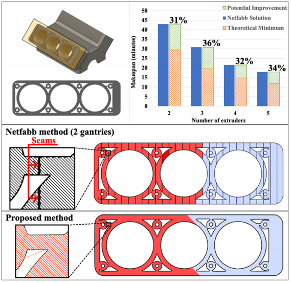
Summary of the result from the case study of Netfabb’s performance and toolpath illustrations (30% infill) of the Netfabb method and proposed method.

 The goal of this methodology is to consider collision constraints for 2-gantry 3D printers, while also minimizing the single layer makespan (printing time). 

The shortcomings of current methods, the lack of published research on concurrent FFF, and the need for an alternative path-planning method for multi-gantry FFF 3D printers inspired the development of a new method,” the researchers explained. “Although the multi-gantry system is one of several kinematic configurations of concurrent FFF 3D printing, increased understanding it can provide insights into the development of generalized multi-tool path planning problems for AM processes.”

A Tabu Search (TS) heuristic (practical method of problem solving), which uses a memory mechanism to store information to help guide future searches, was used to optimize the single layer makespan in the methodology by adjusting the toolpath for the infill. The TS incorporates three main operators:

  1. The local swap operator swaps two raster segments printed by the same printhead to reduce the rapid movement distance
  2. The global swap operator exchanges two raster segments that have been printed from different printheads
  3. The rebalancing operator allocates one raster segment from the printhead with a higher makespan to the other printhead

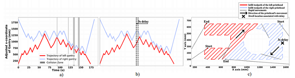
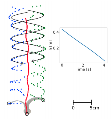
a) trajectory plot produced by the collision checking algorithm (tested layer A with 1% infill) showing 4 possible collisions (i.e. vertical gray bars); b) trajectory plot after adding 3 seconds’ delay to resolve the first collision (note that it also resolves the following collisions); c) toolpath representations of solution in 2b. The arrows indicate the two gantries are moving in the opposite directions toward each other when printing the associated raster segments. By adding 3 seconds delay at the dwell location, the two gantries synchronized and avoided the potential collision.

“At the beginning of the algorithm, with a randomized initial solution list, the global swap operator is favored. Due to the high degree of randomization of the sequence and the high number of collisions, adding delays might not be able to resolve the collisions, in which case the two gantries will work in sequential order. The goal is to segment the appropriate raster segments into two groups, one group for each printhead. The number of collisions begins to decrease as a result. Later on, the local swap slowly becomes more attractive.”

Two complementary algorithms work with the TS: a collision checking algorithm, which detects any potential collisions, and a collision response algorithm, which finds points in the toolpaths where a collision can be avoided by adding a delay.

The researchers explained, “An efficient collision checking algorithm should be able to quickly detect the collisions for a large number of raster segments and identify the corresponding movements that caused them. By utilizing a unique characteristic of the multi-gantry FFF machine, the process of identifying the collisions can be simplified. In such configuration, the collisions happen every time the gantries collide in the x-direction. In other words, a collision happens when the two gantries share the same workspace at any moment in time. A safety distance between two gantries was added when constructing the trajectory plot as a way to keep the gantries away from each other even though the collision is detected.”

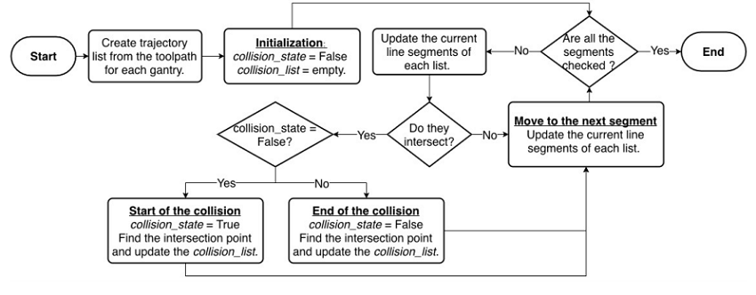
Flowchart of collision checking algorithm

“The motivation of the collision response algorithm is to identify an opportunity for resolving the collision by adding a delay. It is worth mentioning that each vertex on the trajectory plot represents a potential place to insert the delay.”

This algorithm has 4 steps, the first being to identify a set of line segments that are associated with the first collision, and then figuring out whether a delay could fix the collision. Third, the delay is inserted and all future trajectory segments are adjusted, and finally, you move up in time to find the next collision; then, lather, rinse, repeat until the collisions are gone.

The team’s methodology for avoiding 3D printing collisions was thus named Tabu Search with collision checking and response, or TS-CCR.

“The TS-CCR outputs a solution represented as a combined list of sequences of raster segments that must be printed for each printhead,” the researchers wrote. “To get the infill makespan of the solution, an infill toolpath for each printhead is constructed from the aforementioned solution. The collision-checking algorithm then searches for any potential collisions and passes the information to the collision-response algorithm, which introduces delays in order to prevent potential collisions.”

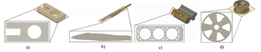
a) tested layer A; b) turbine blade layer; c) engine block layer; d) wheel rim layer. The wheel rim layer is considered a special case since Netfabb did not produce a solution.

To test the TS-CCR’s performance, the team chose four objects, then sliced a selected layer of 0.3 mm from each and computed the results from the theoretical minimum makespan, slicing the layer with the Netfabb Multi-Gantry FFF Engine and the 2018.1.0 Escher plugin, and the TS-CCR.

They collected information, such as build volume and print speed, about the multi gantry 3D printer from the Titan Cronus profile in Netfabb.

For the TS heuristic, the value for the size of the candidate list and tabu tenure were chosen as 10 and 4, respectively. The algorithm terminates if it has been running for 2 minutes since the last improvement,” the researchers explained.

Then, they compared the makespan for three solutions – the theoretical minimum, proposed methodology, and Netfabb for 2 printheads – in a trajectory plot, which shows how the algorithms performed. 55 seconds of delays were added at different points, but because most of these were introduced in the printhead with a shorter makespan, only three total seconds were added to the overall makespan. This plot also shows how important the rebalancing operator is in TS – the gantries completed their work at almost the same time.

Trajectory plot of the result obtained from the TS-CCR (engine block layer with 30% infill). The printing time of the two gantries are 1272 and 1269 seconds, respectively.

“The performance of the methodology varies depending on the complexity of the layer. It can reduce the makespan of the “tested layer A” by 14.48% as compared to Netfabb, while the improvement reduces to 10.18% for the “engine block” layer. Since only one printhead is utilized to print the perimeter shells, the time spent on printing the shells likely offsets the improvement of the proposed methodology for any complex layer. Since this work focuses on only optimizing the infill, the method of allowing multiple printheads to print the perimeter shell at the same time can be implemented to reduce the makespan further,” the researchers wrote.

While there are only about 11 minutes of makespan reduction for the tested layer over the single printhead, this kind of improvement can accumulate across all layers and reduce the overall time.

a) makespan comparison for 3 layers (tested layer A, engine block, turbine blade) at 30% infill, where the proposed method can yield a solution with a shorter makespan than the solution obtained from Netfabb; b) makespan comparison for the “wheel rim” layer, where Netfabb did not produce a solution. The result from the methodology is compared to the makespan if the same layer is printed by the single printhead and the theoretical minimum.

The team’s proposed TS-CCR methodology can solve major issues of using multi-gantry FFF 3D printing, such as carefully planning to avoid mutual collisions while also not compromising the strength of the final print.

Discuss this and other 3D printing topics at 3DPrintBoard.com or share your thoughts below. 

The post Reducing 3D Printing Collisions with Toolpath Optimization Methodology appeared first on 3DPrint.com | The Voice of 3D Printing / Additive Manufacturing.

Experimenting with Transmitting EMG Signals to 3D Printed Myoelectric Prosthetic Hands

Amputees have some choices when it comes to 3D printed prosthetic hands, in regards to whether the artificial limb is operated by mechanics or neurological signals. We’re also seeing examples of 3D printed myoelectric prosthetic hands, which is an externally powered artificial limb controlled by the electrical signals that are naturally generated by our muscles.

A group of researchers from the Gujarat Institute of Technology and Government Engineering College, which are both in India, recently published a paper, titled “Wireless Transmission of Electromyography (EMG) Signals to operate 3D Printed Myo-Electric Hand,” that explains their new methodology of wirelessly transmitting Electromyography (EMG) signals to a 3D printed myoelectric prosthetic hand.

The abstract reads, “Sometimes in case of particular amputees, fetching EMG signals by sensors is not possible from that destructed muscles but, EMG generated from healthy muscles besides that amputees can be used in the transmission of signals. The objective of this research is to generate the new technique for transmitting EMG signals without wire from any adequate healthy muscles. In this methodology, we used the EMG sensor to detect EMG signals, which perform a pre-processing task and featured extraction on EMG signals by using a microcontroller. That extracted output then applied to universal remote control transmitting circuit as input which sends the signals to the receiver circuit, output signals from that receiver circuit directly applied to servo motor of a myoelectric prosthetic hand. The objective of this research to fetch and carry EMG signals from the healthy muscle and train the victim suffering from amputee in which acquiring adequate EMG signal from very adjacent tissue of damaged area is not possible due to burning and inflammatory issues.”

The researchers wrote that myoelectric hands are more reliably and accurate, and that amputees can configure the motion of the hands in a much more natural way, with more freedom. EMG-based myoelectric hands are popular on the market, because they are more efficient. You can see how the team’s 3D printed myoelectric prosthetic hand, which is controlled through wireless EMG transmissions, works in the diagram below.

Block Diagram of Wireless EMG Control for Prosthetic Hand

The team conducted their experiments on the right hands of six people, ages 21-24, that were not differently-abled, and two with below the elbow amputations. Because the subjects all had major differences in body muscle fat, the results of electrical signal powering the prosthetic were altered a little more than normal.

EMG signals are associated with the muscle’s contraction and relaxation movements, but the body’s signals are of low potential, so amplifier circuits and filters are needed to help get rid of unnecessary noises. Traditional EMG analysis instruments often use painful needle electrodes, but wireless EMG ideology can help in situations where it’s not possible to get adequate signals across the muscles for various reasons, such as muscle fatigue and allergic reactions. In this experiment, a microcontroller with an embedded 8 bit ADC (Analog to Digital Converter) was used to sample the signal, while a motor driver circuit controlled the amount of voltage and current supplied to drive the motor.

“There are many modules and terminology that are available in market like Bluetooth and Wi-Fi connectivity. But the most significant concern undertaken by our study that all modules requires basic power consumption and first time pairing and in such case that doesn’t proved to be most useful due to some connectivity issue. Therefore, developing RF Based Wireless unit opted by our team,” the researchers wrote. “Since we had utilize almost 5 servo motors, we need to develop multichannel wireless TX that can control up to 5 different appliance or motor. Wireless TX concept is based on transmitting our low frequency signal from one end to another by modulating with predecided carrier frequency which has high frequency which can transmit signal at a large range, even prosthetics don’t require such a high range. We had used 27MHz of frequency to modulate our low energy signal which is encoded to certain signal by IC TX-2B.”

Wireless vs wired prosthetic hand

The team noted that by 3D printing the hands, there are more opportunities to design accurate parts for good results. They used a Makerbot 3D printer to make the hands out of ABS and PLA, with 90 to 100% infill and normal print speed. Supports were used, and the hands were polished for a better overall aesthetic. Each hand had metacarpal fingers and an enclosure, wrist, and ring of the wrist, along with a standard below elbow piece to enclose and link the structure so the fingers could be moved.

In order to learn more about the participants’ muscles and find out which ones generated the signal most dominantly, an EMG spectrum analysis was performed on each person before muscle sensors were deployed on their arms. This would allow them to avoid inconsistent signals.

One of the amputees could not generate an EMG signal from his lower elbow, possibly due to muscle destruction or a lack of physiotherapy exercise.

Motor Moving Mechanism of the Prosthetic finger

“Wireless EMG Based Prosthetic Hand can be consider meaningful for both condition either person suffering with wrist disarticulation or standard above elbow,” the researchers concluded.

“Wireless method completely isolates the sensor and actuator portion because they get communicate by radio frequency network only which drives by low power.

“Overall, we had taken observation that it is novel technology to transfer EMG signal from healthy muscles rather than amputate hand to the sensor to operate prosthetic hand.”

Co-authors of the paper are Sunny M. Patel, Dinesh R. Damodar, Chintan A. Patel, and Raj B. Patel.

Comparing the Operational Characteristics of Plastic 3D Printed Spur Gears

Back to back gear test rig used in performed experimental research.

Spur gears, which can achieve high transmission ratio and energy efficiency, are comment elements used in the transmission of motion and high intensity power for mechanical power drives, i.e. belt drives, chain drives, and cylindrical gear drives. These power transmission elements are exposed to non-conforming operating conditions in terms of load and speed, and are also applicable at high speeds. Spur gears play a big role in mechanical engineering, and are often tested in back to back gear test rigs in order to gain data regarding the gear teeth flanks’ surface load capacity.

A group of researchers from the University of Belgrade in Serbia and the Slovak University of Technology in Bratislava published a paper, titled “The Influence of Material on the Operational Characteristics of Spur Gears Manufactured by the 3D Printing Technology,” on their efforts to test plastic 3D printed spur gears on a back to back gear test rig, in order to increase the use of the technology in manufacturing these gears.

3D printing direction of the 3D printed spur gear.

“In this paper the influence of the material type on the operational characteristics of spur gears manufactured by the 3D printing technology is analyzed, after the experimental testing performed on a back to back gear test rig, in the predefined laboratory conditions,” the researchers wrote.

“For the purposes of this paper, two types of polymeric materials were analyzed. The initial load in the form of a torque that was exposed to the spur gears was held constant, while the number of revolutions per minute of spur gears was varied. The plastic gears tested in this experiment operated in unlubricated working conditions.”

The researchers performed a comparative analysis, using commercially available PLA and ABS materials, on their impact on the 3D printed spur gears’ operating performance. The most common bulk failures in spur gears made of metal are teeth fractures and surface degradation like pitting and scuffing, but the researchers weren’t quite sure if this would be the case for their 3D printed plastic gears.

“With metallic spur gears, the load in the form of torque increases at the appropriate levels while simultaneously controlling the process of surface destruction of the gear teeth flanks,” the researchers explained.

“For the purposes of this experiment, the load in the form of a torque is fixed, that is, the initial moment of constant intensity has value 20 Nm. The torque of this intensity is insufficient to cause premature surface and volume destruction of spur gear teeth. The initially captured torque is “lost” during the wear process. The idea of this experiment was to estimate the wearing intensity for the initially captured load for two different spur gear materials.”

Worn off teeth flank surfaces of the tested PLA gears.

While back to back gear testing typically includes a constant number of revolutions of the electric motor, the frequency regulator was connected to the electric motor for this testing in order to have the ability to change the rotation. The researchers adopted a rotational speed change of 200 rpm, which was changed every ten minutes during the experiment, meaning they reached the maximum 1400 rpm after an hour of testing.

Indicators most commonly used for spur gear operational analysis include temperatures, noise and vibration levels, and the quantity and shape of wear products, and the researchers chose vibration (RMS acceleration) and temperature as the main indicators for their 3D printed ones. A thermal imaging camera was used to record the meshing temperature field of the 3D printed spur gears, while an SKF Microlog Analyzer GX collected information on the vibrations.

“Knowing the number of teeth of the tested spur gears, as well as their number of revolutions, a change in the amplitude of the vibration level is observed over time, by distinguishing the peak resulting from the meshing of the plastic spur gears,” the researchers explained.

In the first five minutes of the experiment under 200 rpm, there was hardly any vibration observed; additionally, in the first ten minutes under 200 rpm, the temperature of the PLA gears was about 20% higher than that of the ABS gears. Eventually, the 3D printed ABS spur gears endured roughly 30 minutes of work before experiencing failure in their teeth at 600 rpm, while the 3D printed PLA spur gears lasted for 90 minutes at 1400 rpm with no visible fractures, but showing “evident teeth contact surface destruction.”

Failure at the teeth roots of the tested ABS gears.

“In the interval from 5 to 15 minutes, vibrations behaviour of ABS and PLA plastic gear pairs is inverse comparing to their thermal behaviour,” the researchers wrote. “The vibrations of ABS plastic gears is higher (RMS=0,18 ms-2) than the ones made of PLA plastic (RMS=0,06 ms-2). Increasing the rotational speed from 300 up the 400 rpm, the vibration of both gear pairs significantly rises (up to RMS=0,72 ms-2). After 400 to 500 and 600 rpm, the vibration levels are declining. After 30 minutes of testing with 600 rpm, just before tooth of ABS gear pair fractured, the level of RMS accelerations was 0,3 ms-2. The vibration level of PLA plastic gear pair vary with an increase of rpm and oscillate around 0,25 ms-2. At the end of experiment (on 1400 rpm) the vibration values of PLA plastic gear pair is increasing to 0,5 ms-2, probably due to gear tooth contact surface destruction.”

Based on their findings, the researchers were able to conclude that the 3D printed PLA spur gears had better operational characteristics than the ABS ones.

Co-authors of the paper are Aleksandar Dimić, Žarko Mišković, Radivoje Mitrović, Mileta Ristivojević, Zoran Stamenić, Ján Danko, Jozef Bucha, and Tomáš Milesich.

Discuss this research and other 3D printing topics at 3DPrintBoard.com or share your thoughts below.

3D Printing Helps Scientists to Understand How Seeds Fly

[Image: flickr user frankieleon]

Have you ever gone out into your yard and been surprised by a particular plant or tree that seems to have sprung up out of nowhere? It certainly wasn’t planted by you, so how did it get there? There is more than one possible way it may have happened – a seed could have been dropped or excreted by a bird flying overhead, but the seed also may have come directly from a parent plant, even if that plant was miles away. Blow on a dandelion puff and watch how far the seeds float, especially on a windy day, and it’s easy to see how dandelions end up absolutely everywhere. The dandelion is far from the only plant that sends out flying seeds to be spread on the wind, however. This is the focus of a paper entitled “Minimal terminal descent velocity of autorotating seeds, fruits and other diaspores with curved wings.

“Wind dispersion of seeds is a widespread evolutionary adaptation found in plants, which allows them to multiply in numbers and to colonize new geographical areas,” the researchers explain. “Seeds, fruits and other diaspores spores (dispersal units) are equipped with appendages that help generate a lift force to counteract gravity as they are passively transported with the wind. Seeds with a low terminal descent velocity increase their flight time and the opportunity to be transported horizontally by the wind before reaching the ground. Many plant species are today unfortunately under severe stress and on the verge of becoming extinct due to climate change, timber extraction and agricultural development. The terminal velocity of the seed is a necessary prerequisite for accurate predictions from dispersion models, which can help predict their wind dispersion and influence policy-makers in their conservation and reforestation plans.”

The researchers describe several shapes of windborne seeds and fruits, including single- and multi-winged seeds, many of which are autorotating or autogyrating – think of the whirly seeds that drop from maple trees. In order to better understand the relationship between wing geometry and terminal descent velocity, the researchers 3D printed several models of winged seeds and fruits using a Formlabs Form 2 3D printer. A series of experiments was performed in a large water tank; the 3D printed seeds were immeresed in the water and then released to drift to the bottom. A camera recorded the motion of the seeds from the side of the tank, and images were extracted from the video to track the seed’s lowest point and the wing tips.

The researchers also performed measurements from the top and bottom of the tank, which were found to be in excellent agreement with the measurements taken from the sides. They then developed formulas that showed the optimum shapes for the seeds’ wings.

“Our results point to geometrical shapes of the wings of multi-winged seeds, fruits and diaspores, which provide them with an optimal dispersion potential i.e. maximal flight time, and compares favourably with wing geometries found in the wild,” the researchers conclude. “For whirling fruits to maximize the time they are airborne, their appendages that function as wings must not curve too much or too little.”

Authors of the paper include Richard A. Fauli, Jean Rabault and Andreas Carlson.

Discuss this and other 3D printing topics at 3DPrintBoard.com or share your thoughts below. 


3D Printing News Briefs: October 10, 2018

It’s business news as usual to kick things off in today’s 3D Printing News Briefs, and then we’re moving on to a little medical and metal 3D printing news, followed by a 3D printing experiment and a superhero-sized 3D printed statue. The LEHVOSS Group is expanding the production capacities for its LUVOCOM material, DyeMansion has announced that its new RAL colors are now available, and the Million Waves Project receives a large grant from Shell Oil. A medical technology company is using HP’s Multi Jet Fusion to 3D print dental aligners, a YouTube video shows the depowdering process for a metal 3D printed turbine, and an experiment shows if it’s possible to use a DLP 3D printer for PCB etching. Finally, WhiteClouds designed and 3D printed a huge statue of She-Ra for a special event.

LEHVOSS Group Expanding LUVOCOM Production Capacity

Not long ago, the LEHVOSS Group, which operates under the management of parent company Lehmann&Voss&Co., revealed that that it would be showcasing its high-performance, thermoplastic LUVOCOM 3F 3D printing compounds at upcoming trade shows. Now, in order to keep meeting the ever increasing demand for these materials, the company has taken important steps, such as constructing a new laboratory and innovation center in Hamburg and commissioning an additional compounding line, to expand the worldwide production capacities for LUVOCOM.

“At the same time, these investments are just another consistent step within the framework of our long-term growth strategy,” said Dr. Thomas Oehmichen, a shareholder of Lehmann&Voss&Co. with personal liability. “Additional extensive investments in the expansion of our plastics business are currently the subject of detailed planning and are set to follow shortly.”

DyeMansion’s New RAL Colors Available

While attending the TCT Show in Birmingham recently, DyeMansion launched three machines that work together to depowder, surface treat, and dye 3D printed parts. The DM60 is the fully automated dyeing part of the system, and the company added a brand new palette of 170 standard RAL colors for PA2200 to its portfolio to let people expand the color range of the system significantly.

DyeMansion has now announced that its new RAL colors for the PolyShot Surfacing (PSS) finish are now available for DM60 color cartridges, and can be ordered via the DyeMansion On-Demand Service. To check if your favorite colors are available, type in the RAL color code on the website. To learn more about the RAL palette and the Print-to-Product workflow, visit DyeMansion’s booth 3.1-G61 at formnext in Germany next month.

Shell Oil Gives Million Waves Project a $5,000 Grant

About 40 million people in the developing world don’t have access to the prosthetic limbs they desperately need, while an estimated 28 billion pounds of plastic trash is dumped into our oceans each year. 501c(3) non-profit organization the Million Waves Project is working to fix both of these problems by using recycled ocean plastic to make inexpensive, 3D printed prosthetic limbs for children. The organization is pleased to announce that it will be now be able to make even more 3D printed prosthetics for kids thanks to a $5,000 grant that Shell Oil is providing.

“We are so excited to partner with this incredible nonprofit that aims to help serve the millions of people in need of prosthetic limbs,” said Brenna Clairr, an external relations advisor at Shell. “Our vision at the refinery is to proudly fuel life in the Pacific Northwest for our employees, contractors and our community, and we help bring that vision to life by collaborating with organizations like a Million Waves Project.”

HP’s MJF Technology Used to 3D Print Dental Aligners

Swiss medical technology company nivellmedical AG is focused on developing, manufacturing, and distributing nivellipso, a novel clear aligner system for correcting misaligned teeth. The system, a more aesthetically pleasing alternative to the conventional fixed braces, uses biocompatible, invisible plastic splints that gently move teeth to the desired position. The company is using HP’s Multi Jet Fusion technology to make its  dental aligners, which has helped improve its digital workflow.

“We are putting our focus on precision and quality work,” said Dr. Milan Stojanovic, the head of the nivellmedical board. “3D printing technology has simplified a lot of the production of aligners.

The patient’s mouth is scanned, and the scan is then sent to the laboratory, where a model is 3D printed and used to properly fit the aligners before they are shipped out to the patient. Learn more about the process in the video below:

Depowdering a Metal 3D Print Build

Have you ever seen those videos on the internet that are supposed to be ‘oddly satisfying’ and stress-reliving in a way you can’t quite figure out? The ones that show a ton of matches lighting up in a pattern, or someone slowly squishing their hands in a beautifully decorated pile of slime or some other weird material? Nick Drobchenko, a YouTube user from Saint Petersburg, has now introduced the 3D printing equivalent with his video of using a brush to slowly remove the metal powder from a 3D printed part.

“Hollow stainless steel turbine, 90mm diameter. Printing time 4.5 hours,” Drobchenko wrote in the video description. “Printing cost $140, about 30 cm3.”

If the video below does not soothe and/or satisfy you, then I’m not sure what will:

Can a DLP 3D Printer Be Used for PCB Etching?

A maker named Andrei who goes by Electronoobs online recently acquired a couple of DLP 3D printers. After reviewing them, he wanted to see if it was possible to use DLP 3D printers to build the mask for PCB etching. So he created an experiment – with surprising results – and published a video about his experience on YouTube.

“I would only use the UV light of the printer to create the mask for the PCB, and then etch it using acid for copper PCBs just as always,” he explained in the video.

In addition to the DLP 3D printers, other things required for this experiment included copper boards, dry photosensitive film, sodium carbonate, latex gloves, and an iron. Spoiler alert – Electronoobs succeeds in using DLP technology to 3D print a mask for PCB etching. To see the rest of his impressive experiment, check out the video below:

3D Printed She-Ra Statue for New York Comic-Con

[Image: Darinda Ropelato via Facebook]

Utah-based 3D printing services company Whiteclouds has plenty of experience with the technology in many applications, from aerospace, gaming, and mapping to medical for both animals and humans. But recently, the employees got to participate in a project that was, as Whiteclouds CEO Jerry Ropelato told 3DPrint.com, “one of the coolest (and funnest) 3D prints” they’ve ever worked on. The company was asked to design and 3D print the statue of She-Ra at the recent New York Comic-Con.

“It was our tallest at 11 foot tall,” Ropelato told us.

DreamWorks and Netflix are bringing She-Ra and the Princesses of Power back to life with an animated series that will begin next month. According to a Facebook post by Ropelato, Whiteclouds enjoyed every bit of the Comic-Con project, which included designing and 3D printing She-Ra’s throne and sword. The team used touch-sensitivity electronics for activating the sound and lighting for the statue, and were proud to have a small part in the She-Ra reboot.

Discuss these stories and other 3D printing topics at 3DPrintBoard.com or share your thoughts in the comments below. 

Inexpensive 3D Printed Membrane Feeder Aids in Malaria Studies

[Image: National Geographic]

According to the Centers for Disease Control, in 2016 roughly 445,000 people around the world died of malaria, a serious disease caused by a parasite that often infects a certain type of mosquito, which in turn feeds on humans. 91% of these deaths were estimated to have taken place in the WHO African region, and most of these deaths were of young children, who are among the most vulnerable in areas of high transmission as they have not developed an immunity to the disease yet.

Malaria is one of the world’s most severe public health problems, and a lot of work has gone into using 3D printing to help diagnose and even cure the disease.

A group of researchers from Imperial College London is studying how malaria is transmitted, which requires mosquito test subjects to be infected with Plasmodium gametocytes – the blood stage parasites that actually cause malaria. In a Standard Membrane Feeding Assay (SMFA) test, an artificial membrane feeding apparatus, which simulates the host’s skin and body temperature, is used to get the mosquitoes to eat reconstituted blood containing the gametocytes. These feeders warm infected blood using glass chambers or electric heating elements, both of which are hard to acquire and expensive to boot.

The team recently published a paper, titled “An inexpensive open source 3D-printed membrane feeder for human malaria transmission studies,” that presents their creation and testing of an inexpensive, 3D printed membrane feeder.

“Presented here is a simple two-piece water-jacketed membrane feeder designed to hold a volume of 500 µl,” the paper reads. “Using the files presented here, the feeder can be 3D-printed directly and inexpensively by stereolithography by any equipped lab or commercial 3D-printing provider. Alternatively, by using a CAD package the size of the feeder can be up- or downscaled to hold more or less volume respectively.”

a) The membrane feeder was designed in two parts, a top chamber that connects to a circulating water bath and a bottom chamber holding a water reservoir and the RBC/gametocyte/serum sample on the underside. b) Both pieces are glued together into a single, watertight unit.

The researchers created the two-part membrane feeder design using the free, open source CAD modeling program Art of Illusion, then had Shapeways 3D print the parts out USP VI medical-grade “Fine Detail Plastic” acrylic resin (VisiJet M3 Crystal). Then, they conducted three independent SMFAs, using the Plasmodium falciparum laboratory strain NF54, in order to compare the performance of their 3D printed membrane feeder to that of a commercial glass feeder.

Comparative P. falciparum SMFAs with a commercial glass feeder and 3D-printed feeder.

According to the study, “Exflagellation rates as well as oocyst counts indicate that there is no significant difference between the two, within the statistical power given by triplicate SMFAs used as standard by the research community.”

The researchers believe that by making the design files for their 3D printed membrane feeder open source, more laboratories will be able to perform these SMFAs, and can even customize the design if necessary.

“The 3D-printed feeder design enables researchers to inexpensively produce their own SMFA feeders as an alternative to expensive and fragile glass feeders that require specialist manufacturing,” the study concludes. “This new 3D-printed feeder can be used in a wide range of applications in addition to standard SMFAs, as it is not limited to the species used here. Application might include the assessment of vector competence for malaria, the epidemiological assessment of the infectious reservoir for malaria, clinical drug trials, and transmission-blocking studies.”

Co-authors of the paper include Kathrin Witmer, Ellie Sherrard-Smith, Ursula Straschil, Mark Tunnicliff, Jake Baum, and Michael Delves. The design files for the 3D printable membrane feeder can be found in the paper.

Discuss this story and other 3D printing topics at 3DPrintBoard.com or share your thoughts in the Facebook comments below.