Improved 3D Printing: Near-Convex Decomposition & Layering

Researchers İlke Demir, Daniel G. Aliaga, and Bedrich Benes tackle one of the most popular topics in 3D printing today: optimization. While the many benefits of digital fabrication are oft discussed—from greater affordability, improved speed in production, and the ability to create and re-design without a middleman—challenges continue to arise due to continual innovation. Ever on the search for perfection, users are continually seeking ways to predict mechanical properties, decrease defects, and monitor additive manufacturing systems.

In this study, the authors focus on reducing the amount of material used, reducing print times, and refining accuracy. Detailing the efforts of their research in ‘Near-convex decomposition and layering for efficient 3D printing,’ we learn more about their ‘divide-and-conquer approach,’ featuring automatic decomposition and configuration of an input object into print-ready components.

“3D printers have both limitations and advantages depending on the coherency between the printer features and the model geometry,” explained the authors. “Instead of relying only on improvements of the 3D printing technology, we provide a solution that optimizes the model in order to maximize that coherence by segmenting the model into easily printable components.”

They noted 15% improvement of quality, 49.4% savings in material, and 50.3% reduction in printing.

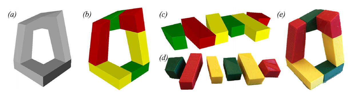
Decomposition for 3D printing: Input model (a), our automatic near-convex decomposition (b), configuration that will be printed (c), individual printed components (d), and the final printed and assembled object (e).

The sample for this study is a polygonal model. Decomposition included separating the beginning clusters into an ‘optimal’ set of components. In the next step they were prepared for printing in a configuration phase, saving time as in most other cases labor is extended as the print bed must be moved down, or the printhead must be moved up. Production is also more efficient as parts are printed at once. In evaluating properties, the researchers examined:

  • Volumetric approximation
  • Number of components
  • Amount of support material
  • Faster print time
  • High quality resulting from less angular surfaces

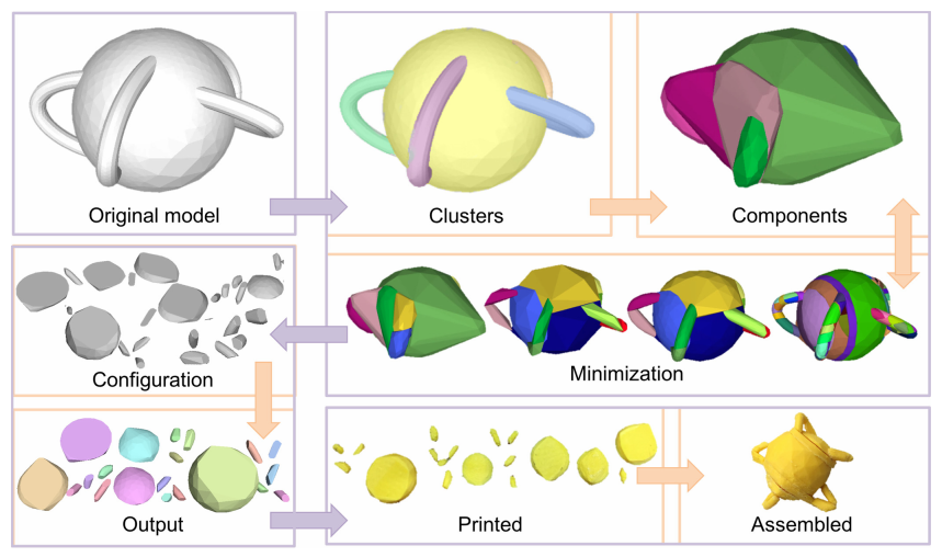
System pipeline: A 3D mesh is first decomposed into clusters and then optimized for optimal components. Afterwards, the components are configured for an efficient layout. Finally, printed and assembled to produce the final physical object.

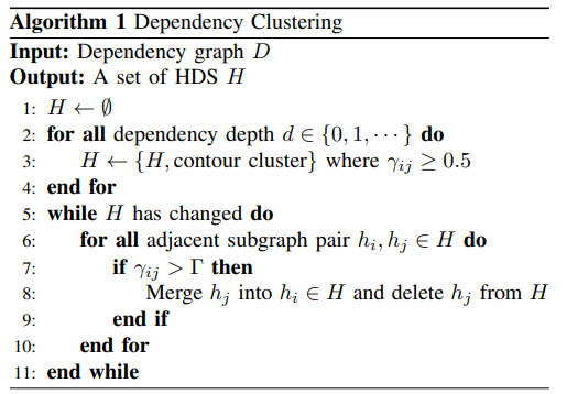
The algorithm consists of subspace creation and segmentation. A set of similarly shaped clusters (triangles) is defined, and then clusters are ‘iteratively merged and split’ for balance.

“During each iteration of this step, we compare cluster-by-cluster, mark similar clusters, and merge-split at the end of each iteration, until convergence. We also highlight that our method uses the same threshold parameter values for all models,” explain the authors.

For improved printing, components must possess:

  • Concavity
  • Surface angles
  • Sizes and Numbers
  • Deviation

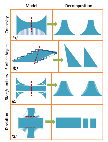
Component properties: Convex components need less support material (a). Better surface quality can be achieved by avoiding near-horizontal angles (b). Balancing convexity and size/number of components prevent over-segmenting (c). Minimizing deviation increases model fidelity (d). The red dashed lines indicate the cut line. The combed area in (a) indicates the support structure, and the combed areas in (c and d) indicate the model deviation.

Of the 20 samples applied to the framework in this study, some were manually modeled, and some were acquired commercially. Complexity averaged 23.9K, with the new method suitable for both solid and shell forms. Preprocessing time for segmentation and configuration was around 15 minutes for a medium complexity model.

Printed examples were compared with the initial and segmented models, ‘with better approximated surfaces, and multi-color support.’ Real models were also examined in their initial form, after supports were removed, and before and after assembly.

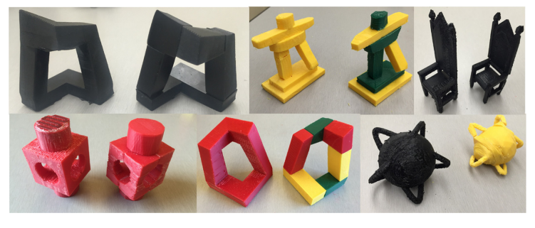
Example objects: We show side by side the printed results of the original and the segmented models

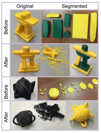
Original vs. segmented models: We show the original and segmented forms of the model, before and after post-processing (removing support material and assembling, respectively).

“… our approach prevents wasting material, and provides higher fidelity objects, with multi-material support. Note that, even if the approximated surface is highly curved, our decomposition finds segments that connect well, even after printing with accumulated printing errors.”

The authors did note, however, that the printed model did not ‘approximate’ the original—although the segmented model did. Upon superimposing printed versions in wireframe, they were able to show that improved approximations can be achieved—using the same printer.

“The coloring in the point cloud version indicates that our algorithm decreased the overall error more than 35% based on the Hausdorff distance of sampled surface points. We have not evaluated based on a measurement of the real printed models, because parameters contributing to this surface error is more constrained in simulation,” concluded the researchers.

“Our results show that the framework can reduce print time by up to 65% (fused deposition modeling, or FDM) and 36% (stereolithography, or SLA) on average and diminish material consumption by up to 35% (FDM) and 10% (SLA) on consumer printers, while also providing more accurate objects.”

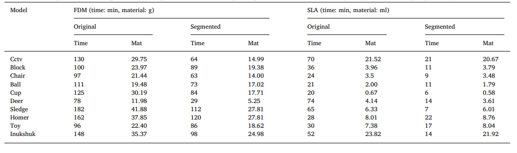
Evaluation: Comparison of the original and the segmented models, their printing times and material consumption, per model and per printer type.

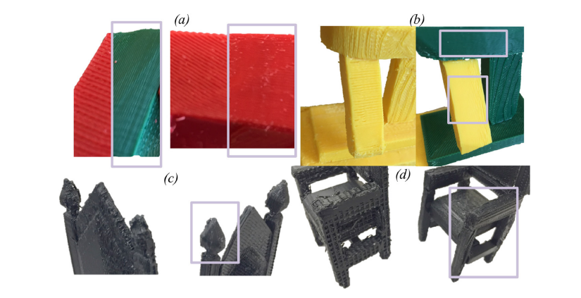
Improvements: Our results are highlighted within boxes. The avoidance of angled surfaces improves surface fidelity (a and b), having no support material protects the deterioration of the object (c), convexity gets rid of the support material (and its scars) from the inside and outside of the objects (d).

What do you think of this news? Let us know your thoughts! Join the discussion of this and other 3D printing topics at 3DPrintBoard.com.

[Source / Images: ‘Near-convex decomposition and layering for efficient 3D printing’]

The post Improved 3D Printing: Near-Convex Decomposition & Layering appeared first on 3DPrint.com | The Voice of 3D Printing / Additive Manufacturing.

Monte Carlo Tree Search: Optimizing Toolpath Planning in FDM 3D Printing

Authors Chanyeol Yoo, Samuel Lensgraf, Samuel Lensgraf, Lee M. Clemon, and Ramgopal Mettu detail their research for improvements in FDM 3D printing, outlined in the recently published ‘Toward Optimal FDM Toolpath Planning with Monte Carlo Tree Search.’

Most toolpath planning in FDM 3D printing consists of input models sliced into layers; however, this can lead to a lack of efficiency in motion at times, especially when the extruder may still be moving but not actually printing. In this study, the researchers set out to compute an efficient and optimal toolpath via a new algorithm using the Monte Carlo Tree Search (MCTS).

“A powerful general-purpose method for navigating large search spaces that is guaranteed to converge to the optimal solution,” the MCTS was analyzed within this study regarding its ability to improve searches.

“To our knowledge, this is the first algorithm for toolpath planning with any guarantees on global optimality,” stated the researchers.

Example model of ‘four nuts’ (a) image, (b) labelled dependency graph, and (c) clustered dependency graph from (b)

Previously MCTS has been useful for solving problems in robotics applications, yielding the desired, greater efficiency in toolpath planning.

“Monte Carlo tree search algorithm is based on biased search algorithm for finding an optimal solution asymptotically. Starting at an initial condition, a tree grows at every iteration. The algorithm finds the next best node in a tree to expand using upper confidence bound (UCB), where UCB balances between exploitation and exploration. Intuitively, the node with higher likelihood of finding a better solution will be selected. Once a node is selected for expansion, one or a number of complete sequences is randomly generated from the node until reaching the end (e.g., end of time horizon),” explained the authors.

“In order to make our algorithm efficient, we also introduce a novel clustering algorithm on the dependency graph for the input model.”

An example illustrating clustering algorithm in Alg. 1. (1) 16 raw contours are clustered into three highly dependent subgraphs (HDS) as shown in (b).

With a dataset comprised of 75 models, use of the MCTS method did demonstrate ‘substantial reduction’ in wasted motion. The authors noted that MCTS performance was like that of their current local search toolpath planner, but overall made it easier for them to investigate difficult in planning with some models.

‘Four nuts’ model. Toolpath for building the part by (a)(d) typical layerwise planner, (b)(e) local search from [6], and (c)(f) proposed MCTS, with red indicating non-printing motion. The solution toolpath for each method is shown in red. Extrusionless distances (in mm) are 16737, 12220 and 11057, respectively.

‘Twisty’ model. Toolpath for building the part by (a) typical layerwise planner, (b) local search from [6], and (c) proposed MCTS, with red indicating
non-printing motion. Solution toolpath for each method is shown in red. Extrusionless distances (in mm) are 25021, 11423 and 11306, respectively.

“A natural question is why one would use MCTS over local search for a given model. Using our empirical studies, it appears that the output of the clustering step and subsequent composition of HDS components of the dependency graph provide guidance as to whether MCTS can achieve convergence,” concluded the researchers.

“As we saw in our empirical analysis if there enough HDS components with respect to the size of the dependency graph then it is highly likely that MCTS will converge to an optimal toolpath. If the number of HDS components is too large, or the average size is too small, then MCTS will have difficulty exploring the toolpath space and may perform worse than local search.”

Colored clusters for example parts

Researchers around the world continue to study ways to refine and use FDM 3D printing, from experimenting with new materials to fabricating innovative medical devices. What do you think of this news? Let us know your thoughts! Join the discussion of this and other 3D printing topics at 3DPrintBoard.com.

[Source / Image: ‘Toward Optimal FDM Toolpath Planning with Monte Carlo Tree Search’]

The post Monte Carlo Tree Search: Optimizing Toolpath Planning in FDM 3D Printing appeared first on 3DPrint.com | The Voice of 3D Printing / Additive Manufacturing.

Short Carbon Fibre-Reinforced Polyamide Using FDM 3D Printing vs. Polymer Injection Molding

Researchers from Spain are investigating more effective 3D printing materials with different techniques in the recently released ‘Investigation of a Short Carbon Fibre-Reinforced Polyamide and Comparison of Two Manufacturing Processes: Fused Deposition Modelling (FDM) and Polymer Injection Moulding (PIM).’

FDM 3D printing is extremely common for digital fabrication by users on all levels, beneficial due to affordability and accessibility—and offering a way to create complex structures for many different applications today, from medical to bioprinting, automotive, and aerospace. Selective laser sintering (SLS) and selective laser melting (SLM) are also methods preferred in manufacturing today, although the researchers note that FDM 3D printing is ‘more developed,’ with the following popular polymers:

  • Acrylonitrile butadiene styrene (ABS)
  • Polylactic acid (PLA)
  • Polyvinyl alcohol (PVA)
  • Polyamides (PA)
  • Polyether ether ketone (PEEK)

Poor mechanical properties are an ongoing issue, related to varying parameters, issues with adhesion, and materials which are not suitable. Composites are often used as a solution, with many different projects employing additives making up new materials like bronze PLA, composite hydrogels, and numerous metals. Carbon and glass are common additions used for strengthening the polymeric matrix, but the researchers note that they have not been the subject of comprehensive studies.

CarbonXTM CRF-Nylon was used with an Ultimaker 2 Extended + to fabricate the samples, designed with Autodesk Inventor, and sliced with Cura 3.5.1.

Stereomicroscope images (×1.25) of the appearance of the injected and different patterned printed samples.

The authors, comparing 3D printing and injection molding capabilities, evaluated fiber length first.

Results of the fibre length distribution in the raw material, injected and printed samples (A) and measurement of diameters in fibres using 400× with a microscope (B).

“The critical length obtained by Equation (1) was