Cell Culture Bioreactor for Tissue Engineering

Researchers from the US and Portugal are refining tissue engineering applications further, releasing the findings of their study in the recently published ‘A Multimodal Stimulation Cell Culture Bioreactor for Tissue Engineering: A Numerical Modelling Approach.’ In creating a new bioreactor for 3D printing, the authors worked to promote reproducibility and optimization, fabricating a design not possible using conventional techniques.

In most bioprinting, cells are seeded onto scaffolds—also the source of much study, whether in regard to new techniques, enhancements, or interface engineering—and then researchers must hope for viability. Promoting cell growth and sustainability is one of the greatest challenges in any type of bioprinting, and often devices like perfusion flow bioreactors are used in replacing culture mediums to remove toxins. In some cases, they are also used for mechanical stimulation through fluid flow shear stress (FFSS). Electric field stimulation devices can also be easily used to encourage cells to grow, mature, and differentiate.

The bioreactor used here was part of a previous study conducted by the authors, but now updated (using SOLIDWORKS 2018 Student Edition ) to include capabilities in E-Field stimulation and fluid flow mechanical stimulation. 3D design was performed in SOLIDWORKS 2018 Student Edition. Assessment of the new design was part of this study, leaving the team to create a numerical finite element analysis (FEA) of the model.

With FEA, the researchers could project input conditions for the bioreactor, further enhancing effectiveness of cell stimulation, determined from in vitro data. Overall, in vitro tests can offer ‘essential’ information for confirming ranges of multimodal stimulation—projected via numerical studies.

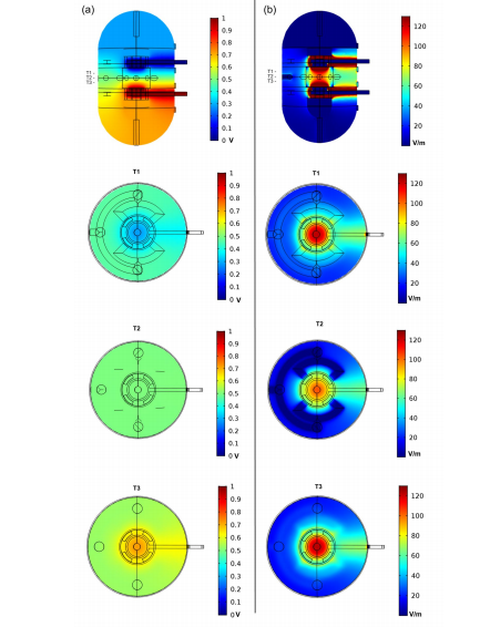
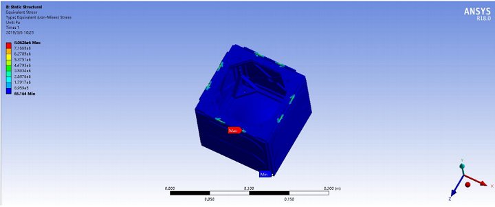
Numerical finite element analysis (FEA) analysis of the proposed bioreactor design with a DC electric stimulation parallel plate capacitor set-up with lateral and top slice views. The three top views represent the ROI upper slice (T1), the ROI middle plane slice (T2) and the ROI bottom slice (T3). (a) Electric potential distribution predicted in the bioreactor due to DC stimulation. (b) E-Field magnitude distribution predicted for the same electric DC stimulation conditions.

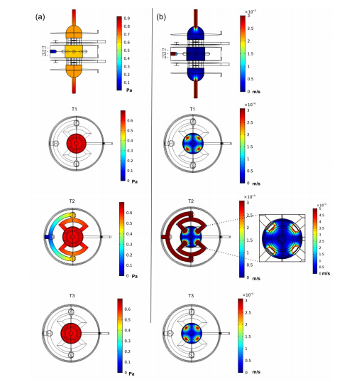
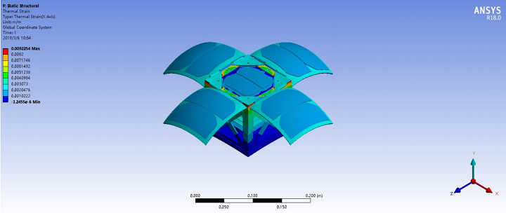
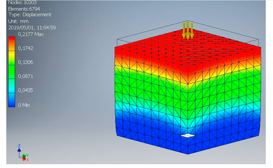
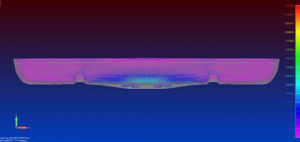
Numerical FEA analysis of the proposed bioreactor design for a laminar perfusion flow with lateral and top slice views. The three top views represent the ROI upper slice (T1), the ROI middle plane slice (T2) and the ROI bottom slice (T3). (a) Pressure distribution predicted considering applied inlets velocity of 0.003 m/s and a outlet pressure of 0 Pa. (b) Fluid velocity distribution predicted for the same inlet/outlet conditions. The velocity distribution at the ROI middle plane slice is presented in more detail in a top view inset at the right of the slice plane.

“Electrical and mechanical stimulation conditions in the region-of-interest (ROI) were considered for bone cell stimulation optimization, according with reference values obtained from two previous in vitro studies on bone cell stimulation, one applying mechanical stimulation, and the other using E-Field stimulation,” explained the authors.

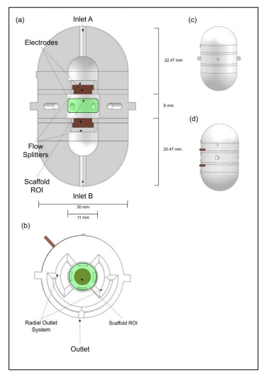
Novel bioreactor design: (a) Vertical cut view of the bioreactor design, where the parallel electrodes set up, the upper and bottom inlets and the inlet flow splitters can be observed. (b) Horizontal cut view of the bioreactor design, where the radial outlet system can be observed. The green regions represent the region-of-interest (ROI) where the scaffold will be placed, represented by a cylinder with 4 mm of height and a diameter of 10 mm. (c) CAD bioreactor design assembled in frontal view, the main outlet hole is visible in the middle. (d) CAD bioreactor design assembled in lateral view, showing both electrode connector wires (in brown).

Flow splitters were added between the inlet and the scaffold, resulting in ‘indirect flow prevalence.’ Inlets and outlets were fitted with hose joiners, connecting them to the perfusion pump. The cell culture chamber was separated into two different areas for cell cultures and cell seeding exercises. Materials for use in the platform were required to be non-toxic and suitable according to ISO 10993-5 standards.

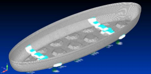
Bioreactor geometry volume mesh created using COMSOL Multiphysics, with 1.9 × 10⁶ elements, and an average element quality of 0.65.

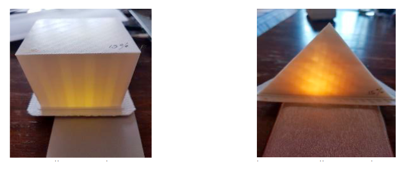
“Accordingly, in the direct contact test, cells cultured in contact with all the materials presented normal fibroblast morphology with no evidence of any inhibition halo effect or cell death. According to the cytotoxicity tests results, all candidate materials are suitable for our bioreactor AM fabrication,” concluded the researchers. “We will consider C8 and PETG as materials of interest for future design fabrication. C8 is a new material with good layer adhesion and surface quality, which are key features for the perfusion flow. The C8 supplier datasheet reveals that this material has a higher tensile strength than ABS, resulting in improved mechanical characteristics, which are important for the overall robustness of the bioreactor to withstand the tightness of pressure chambers.”

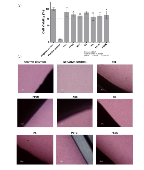
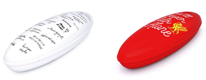
Cytotoxicity assay with L929 mouse fibroblast according to ISO 10993-5 standards: (a) indirect contact (MTT protocol); (b) direct contact (digital images of the material samples and the negative and positive controls, fresh culture medium and Latex, respectively). A one-way ANOVA with no corrections for multiple comparisons (Fisher’s test) statistical analysis was performed using GraphPad Prism6.

“A design–numerical modelling approach will be essential to understand the underlying biophysical effects of electric and mechanical stimuli in cell cultures and can be a powerful tool for standardization of stimulation protocols considering different bioreactor designs and specific TE outcomes.”

What do you think of this news? Let us know your thoughts! Join the discussion of this and other 3D printing topics at 3DPrintBoard.com.

[Source / Images: ‘A Multimodal Stimulation Cell Culture Bioreactor for Tissue Engineering: A Numerical Modelling Approach’]

The post Cell Culture Bioreactor for Tissue Engineering appeared first on 3DPrint.com | The Voice of 3D Printing / Additive Manufacturing.

Researchers Run Simulation Tests on Their 3D Printed CubeSat Before LEO Mission

A pair of researchers from Shantou University in China explored designing and manufacturing a CubeSat with 3D printing, which we have seen in the past. CubeSats, which are basically miniaturized satellites, offer plenty of advantages in space exploration, such as low cost, a short research cycle, and more lightweight construction, but conventional methods of manufacturing often negate these. Using 3D printing to make CubeSats can help achieve accurate details as well.

[Image: ESA]

The researchers, Zhiyong Chen and Nickolay Zosimovych, recently published a paper on their work titled “Mission Capability Assessment of 3D Printing Cubesats.”

“With the successful development of integrated technologies, many spacecraft subsystems have been continuously miniaturized, and CubeSats have gradually become the main executors of space science exploration missions,” they wrote.

The main task driving research paper is an LEO, or Low Earth Orbit, CubeSat mission, which would need to accelerate to a maximum of 5 g during launch.

“…the internal operating temperature range of the CubeSat is from 0 to 40 °C, external temperature from -80 to 100 °C,” the researchers explained.

During the design process, the duo took into account environmental factors, the received impact load during the launch process, and the surrounding environment once the CubeSat reached orbit. Once they determined the specific design parameters, ANSYS software was used to simulate, analyze, and verify the design’s feasibility.

PLA was used to make the mini satellite, which is obviously shaped like a cube. Each cube cell, called a unit, weighs approximately 1 kg, and has sides measuring 10 cm in length.

“The framework structure for a single CubeSat provides enough internal workspace for the hardware required to run the CubeSat. Although there are various CubeSat structure designs, several consistent design guidelines can be found by comparing these CubeSats,” the researchers wrote about the structure of their CubeSat.

These guidelines include:

  • a cube with a side length of 100 mm
  • 8.5 x 113.5 mm square columns placed at four parallel corners
  • usually made of aluminum for low cost, lightweight, easy machining

The CubeSat needs to be big enough to contain its power subsystem (secondary batteries and solar panels), in addition to the vitally important thermal subsystem, communication system for providing signal connections to ground stations back on Earth, ADCS, and CDH subsystems. It also consists of onboard antennae, radios, data circuit boards, a three-axis stability system, and autonomous navigation software.

“The adoption of this technology changes the concept of primary and secondary structure in the traditional design process, because the whole structure can be produced at the same time, which not only reduces the number of parts, reduces the need for screws and adhesion, but also improves the stability of the overall structure,” the pair wrote about using 3D printing to construct their CubeSat.

The mission overview for this 3D printed CubeSat explains that the device needs to complete performance tests on its camera payload for reliability evaluation, and test the effectiveness of any structures 3D printed “in an orbital environment.”

The Von mises stress diagram of the CubeSat structure.

In order to ensure that it’s ready to operate in LEO, the CubeSat’s structures was analyzed using ANSYS’ finite element analysis (FEA) software, and the researchers also performed a random vibration analysis, so that they can be certain it will hold up under the launch’s impact load.

“The CubeSat structure is validated by the numerical experiment. During launch process, CubeSat will be fixed inside the P-Pod, and the corresponding structural constraints should be added to the numerical model. In addition, the maximum acceleration impact during the launch process should also be considered. Static Structural module of ANSYS is used for calculation and analysis, the results show that the maximum stress of CubeSat Structure is 8.06 MPa, lower than the PLA yield strength of 40 Mpa,” the researchers explained.

Running in LEO, the 3D printed CubeSat will go through a 100°C temperature change, and the structure needs to be able to resist this, so the researchers also conducted a thermal shock test, which showed an acceptable thermal strain.

The thermal strain diagram of the CubeSat structure.

The team also conducted random vibration simulation experiments, so they could conform the structure of the 3D printed CubeSat to emission conditions. They simulated typical launch vibration characteristics, using NASA GEV qualification and acceptance as reference.

“The specific contents of the experiment include “Harmonic Response” and “Random Vibration”. Two identical harmonic response were performed before and after the random vibration test to assess the degree of structural degradation that may result from the launch load,” the researchers explained.

“This experiment helps us to evaluate the natural frequency of the structure, and the peak value indicates that the tested point (bottom panel) has reached the resonant frequency.”

Pre/Post Random Vibration test comparison between the curves of Harmonic Response.

As seen in the above figure, both the trend and peak points of the two curves are close to each other, which shows that there was no structural degradation after the vibration test, and that the structure itself conforms to launch stiffness specifications.

“As the primary performer of today’s space exploration missions, the CubeSat design considers orbit, payload, thermal balance, subsystem layout, and mission requirements. In this research, a CubeSat design for performing LEO tasks was proposed, including power budget, mass distribution, and ground testing, and the CubeSat structure for manufacturing was combined with 3D printing technology,” the researchers concluded.

“The results show that the CubeSat can withstand the launch loads without structural damage and can meet the launch stiffness specification.”

Discuss this and other 3D printing topics at 3DPrintBoard.com or share your thoughts below. 

The post Researchers Run Simulation Tests on Their 3D Printed CubeSat Before LEO Mission appeared first on 3DPrint.com | The Voice of 3D Printing / Additive Manufacturing.

South Africa: FEA & Compression Testing of 3D Printed Models

Researchers D.W. Abbot, D.V.V. Kallon, C. Anghel, and P. Dube delve into complex analysis and testing in the ‘Finite Element Analysis of 3D Printed Model via Compression Tests.’ For this study, the researchers used an FEA tool for simulation and testing of 3D printed parts, with a central focus on experimenting with ‘specific imposed conditions’ on the sample models—employing a strategy that allows for much faster, more affordable assessment of parts.

FEA allows researchers (and ultimately, manufacturers) to prove a variety of different prototypes created through other methods—but now a serious focus is being placed on parts printed in numerous different materials, to include ABS, PLA, and more. Square block samples were chosen for the study due to the potential for better accuracy and distribution of stress along surfaces—with the goal of allowing engineers to finally ‘trust’ FEM in terms of 3D printed objects.

Properties of some 3D printing materials.

Compression testing involved labeling 3D printed samples as either isotropic or anisotropic, with a focus on avoiding anisotropy and inter-layer voids. In examining the samples, the researchers were able to see the internal structures of FDM 3D printed parts, along with evaluating densities. Both experimental and computational tests were performed.

(left) 15% quality prototype in ABS (right) 85% quality prototype in ABS

“Results obtained using Autodesk Inventor are compared to the experimental test results. The arrow represents the direction in which the load has been applied to that of the axes experiencing the load. The horizontal axes, the original axis that the objects are printed on, representing an axially distributed load from above, against the grain of the layers, the vertical axis represents an axial load that would be experienced from the side of the test specimen, with the grain of the layers.”

FEA is centered around both the materials and techniques used, along with design—and the researchers point out that this could be different depending on the simulation software used. Both porosity and adhesion are both issues too. The researchers continued to note the ‘large discrepancy’ also between both experimental and simulated results, with test pieces exhibiting 50 percent more solidity than the experimental samples.

(left) before applied load (right) after applied load

On noting that samples ‘behaved poorly’ regarding horizontal/perpendicular loads, the researchers realized the 3D printed block samples were anisotropic. Infill simulated results and experimental results differed greatly too, as the Autodesk design and simulation were viewed as a solid (instead of porous) object; in fact, in some cases, the samples were not similar at all.

Practical test results

In observing samples (or functional parts), it is critical to evaluate:

  • Area of application
  • Environment of use
  • Operational associated stress at specific axis

“The results obtained from this study on different materials at different applied loads across the two different layering axes showed a large variation in compressive strength,” concluded the researchers. “This establishes that the design of 3D parts strongly depends on the application of the part.”

While 3D printing offers a wide range of benefits, the ability to edit designs and create one iteration after another at will is one of the greatest draws in comparison to more conventional methods of production. Researchers today are engaged in many different types of feasibility studies, ways to introduce new workflow features and learn more about cost analyses.

What do you think of this news? Let us know your thoughts! Join the discussion of this and other 3D printing topics at 3DPrintBoard.com.

Maximum displacement at 12200N for ABS Plastic using Autodesk Inventor

[Source/Images: ‘Finite Element Analysis of 3D Printed Model via Compression Tests’]

The post South Africa: FEA & Compression Testing of 3D Printed Models appeared first on 3DPrint.com | The Voice of 3D Printing / Additive Manufacturing.

No carbon fiber necessary: Dr. Adrian Bowyer unlocks stronger 3D prints

In a blog post for RepRap Ltd. Dr. Adrian Bowyer, the inventor of self-replicating 3D printers and winner of our Outstanding Contribution to 3D Printing, has described a potential method for creating stronger 3D printed objects. A novel approach, Dr. Bowyer’s method demonstrates a way of 3D printing fiber reinforcements without actually using a fiber-reinforced […]

3D Printing Used to Decorate Biodegradable KOFFINs that are Personalized for the Deceased

While the way we live is vastly different from the way we did 100, 50, and even 20 years ago, the way we say goodbye to loved ones when they’ve passed away is still pretty much the same. Funerals are not easy for a number of reasons, but the last thing on anyone’s mind should be the cost of these emotional events and ceremonies; unfortunately, that’s not often the case. According to SunLife, funeral costs have shot up over 70% in the last decade.

With this in mind, Koffin, a Liverpool startup founded by artist Gina Czarnecki in 2014, is working with business program LCR 4.0 and using Industry 4.0 technology – specifically 3D printing and advanced material testing – to help cut down on the cost of funerals with customizable, biodegradable eco-coffins.

“Funeral prices are increasing drastically, and people deserve the right to a personalised send-off that isn’t going to break the bank. Planning a funeral can be a difficult time, but we’ve found that having something tangible to take control of and make your own improves people’s wellbeing and peace of mind,” said Czarnecki.

“The work with LCR 4.0 has enabled us to test our design that creates a cost-effective alternative that emits less CO2 emissions than a natural plant.”

Together with brand consultant Clare Barry, Czarnecki set out to redesign the coffin – typically a narrow wooden box. But a KOFFIN, according to the startup’s website, is “a light, eco-friendly capsule made from bioplastic,” which is definitely different from the more traditional, pricey Victorian-style coffins we’re used to seeing.

“The way we currently bury or cremate our loved ones is poisoning the earth,” the Koffin website states.

“Besides… your funeral is your last hurrah, right?

“…So shouldn’t your coffin be as unique as you are?”

The 100% biodegradable KOFFINS were created to help people take back their rights to a personal, affordable funeral. They are made with a lignin-based biopolymer and don’t require any glues or metals to hold them together. They produce less ash residue than other coffins, are leak-proof without having to use wax linings, and will decompose in the earth just like natural tree wood. Additionally, the oval capsules can be completely personalized with different colors, hand-written messages, photographs, and a variety of attachable, 3D printed decorations.

During the development of the KOFFIN prototype, the startup was in need of expert technical support during testing. So Koffin turned to LCR 4.0, partially funded by the European Regional Development Fund, and its partners Sensor City and Liverpool John Moores University to test its inexpensive, sustainable prototype, and use 3D printing for added personalization.

“Koffin is unlike any other start-up that we’ve helped to date,” said Jaime Mora-Fernandez, LCR 4.0 product design engineer at Sensor City. “The work carried out illustrates how new technologies can help businesses in a wide variety of sectors transform the way they approach the design and manufacturing process.”

The LCR 4.0 team at Sensor City helped Koffin complete a finite element analysis (FEA) of the design to find the right material thickness to withhold sufficient pressure. This helps reduce material costs, which will trickle down to lower consumer costs. Then, the partners tested the prototype, and completed a report that concluded the material’s thickness would be robust enough for its purpose.


After four long years of development, the startup has officially gone into production with its first run of biodegradable, customizable, eco-friendly KOFFINs.

“Our involvement with the LCR 4.0 scheme has resulted in outputs being produced in a timely and efficient manner, using expert advice and linking disciplines seamlessly,” said Czarnecki.

Starting today, 20 of the KOFFINs, decorated through a national public call-out, will be displayed at the Oratory, next to the Anglican Cathedral, in Liverpool; some of them even bear some interesting 3D printed decorations. Soon, the startup will also launch a Kickstarter campaign in order to raise the necessary funds to take the KOFFINs to market.


This isn’t the first time that 3D printing has been utilized in the death care industry. We’ve seen 3D printed urns, 3D printed busts of the deceased, and even 3D printed jewelry made from the ashes of our loved ones. As 3D printing also comes into play often with sustainability efforts, the KOFFINs seem to be a perfect mix of life and death.

Discuss this story and other 3D printing topics at 3DPrintBoard.com or share your thoughts below.