What is Metrology Part 21 – Getting Started with Processing

3D Environment Simulation in Processing

In the previous article, I showed the awesome coding framework of Processing. It is fun and interactive for anyone new to code. It makes learning a simple breeze, and it lines up a lot with the topics we have covered within this series thus far. These topics include image processing, 3D image rendering, 3D scanning, pixelation, image restoration, and a slew of other applications. With this article, I will show you how to get started with this program.

To get started, one should visit Processing and their website. From there, you can go to their downloads page and find the corresponding installation package that is right for your system. The package for Processing will be found in a zip file in your downloads section once it is unpacked from the website. Within this download package you will click through it to find an icon that says processing. Once you click this your computer will prompt you to extract the file into a different location. After this you may now use Processing.

Processing Sketchbook

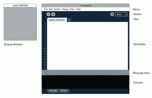
Once you open Processing you will notice the sketchbook and developing environment. That is where all of the code will be run and executed. In order to code within this environment, one needs to understand how to manipulate movement and vision within the 2D realm first before moving to 3D. I think having a solid foundation within 2D leads to better 3D thinking because geometry naturally flows this way. Processing is object oriented and it utilizes rotational and translational commands to make interesting visuals. The majority of commands used in 2D will be applicable to 3D. Processing fortunately has a 2D transformation tutorial online that is a great starting point for explaining the capabilities. Below is a snippet of code that is from the processing site and it has comments on what these lines mean. 


void setup(){

  size(200,200); //size of the window

  background(255); //color value of the background

  noStroke(); //disables the border drawing of the stroke

  //draw the original position in gray

  fill(192); //Sets the color used to fill shapes.

  rect(20, 20, 40, 40); //draws the rectangle with these dimensions  

  //draw a translucent blue rectangle by translating the grid

  fill(0, 0, 255, 128); //fills a rectangle with the blue color

  pushMatrix(); // Pushes the current transformation matrix onto the matrix stack.

  translate(60, 80); //translates the original rectangle 60 units right and 80 units down

  rect(20, 20, 40, 40); //draws the location of the translated data of the original matrix

  popMatrix(); //  Pops the current transformation matrix off the matrix stack.

}

To initialize a build environment in Processing, one needs to setup the environment. Setup calls a function for a viewport to see the digital code. The window size is denoted as well as the background color. The noStroke() function disables Processing and its automatic border drawing for images. 

Executed Script in Processing

Then a fill function is used to color any shape after this definition to be this color. To set the dimensions of our box, we used the rect() function. Then we wanted to create a new blue rectangle so we applied the fill function again but with different values. After this we want to apply translations to the original matrix data we had for the rectangle in terms of location. The pushMatrix() command essentially opens up a loop of interaction within our code to allow us to independently control objects within our environment.  Then we are able to apply the translate function to our original matrix data. In this case we translated the data to the right 60 units and down 80 units. Then we ended this cycle by applying the command popMatrix(). 

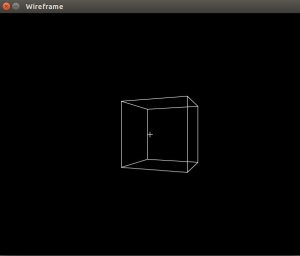
3D Wireframe Processing

Whenever one wants to code, it is good practice to know what every command or function within your code means. Without knowledge of this, you are going to become a copy and paste coder who does not understand the nuances within their own code. It also will take you a bit more time to go through programming tutorials when you stop to learn exactly what everything means, but at a certain point you will gain a greater overall scope of the tools you have at your disposal. With this basic code example, we can expand our skills and apply this in 3D. In the next article, I will show how to do so. 

The post What is Metrology Part 21 – Getting Started with Processing appeared first on 3DPrint.com | The Voice of 3D Printing / Additive Manufacturing.

What is Metrology Part 14: Image Restoration

Art Restoration and 3D Printing

Through this metrology series, I hope readers are making this realization: We as humans have faulty perception, and we try to understand our world as precisely as we can. The tools we use to measure items within our world are prone to error, but they do the best they can to reveal the essence of reality. The common adage is that a picture says a thousand words. If one has a blurry or weak picture, the words said are mostly confusing. Devices that take images can be used for metrology purposes as we have discussed earlier. The data that we capture in forms of images is necessary for high resolution and precise metrology methods. How do we make sure that images are giving us words of clarity vs. confusion?

Image restoration is the operation of taking a corrupt or noisy image and estimating the clean, original image. Corruption may come in many forms such as motion blur, noise, and camera misfocus. Image restoration is different from image enhancement in that the latter is designed to emphasize features of the image that make the image more pleasing to the observer, but not necessarily to produce realistic data from a scientific point of view.

Certain industries are heavily reliant on imaging. An example of the interdisciplinary nature of imaging and metrology is found in the medical sector. Biomedical imaging techniques need to be extremely precise for accurate measurements of internal organs and structures. Size, dimensionality, and volume are items that need high precision due to their affect on human life. Without proper images of these items, doctors and physicians would have a difficult time in giving proper diagnoses. Another important caveat to remember is the ability to replicate these structures through the use of 3D printing. Without accurately measured dimensions from 2D images, there would be a lack of precision within larger 3D models based off of these 2D images. We have talked about image stitching and 3D reconstruction previously. This is especially important within the medical field in the creation of 3D printed phantoms.

One can apply the same concept and thought process to the automotive industry. The automotive industry is all about standardization and replicability. There needs to be a semi-autonomous workflow ingrained within the production line of a vehicle. 3D scans are taken of larger parts that have been fabricated. With these original scans, replicability within production is possible. There still lies a problem of precision within an image. There are a lot of variables that may cause a 3D scan to be unreliable. These issues include reflective or shiny objects, objects with contoured surfaces, soft surfaced objects, varying light color, opaque surfaces, as well as matte finishes or objects. It is obligatory that a 3D scan is done in an environment with great lighting. With all of these issues, image restoration is essential with any scan because it is nearly impossible to have a perfect image or scan. Within the automotive industry, the previous problems are very apparent when scanning the surface of an automotive part. 

There are 4 major methods to image restoration that I will highlight here, but will expand upon within further articles.

Inverse Filtering

Inverse filtering is a method from signal processing. For a filter g, an inverse filter h is one that where the sequence of applying g then h to a signal results in the original signal. Software or electronic inverse filters are often used to compensate for the effect of unwanted environmental filtering of signals. Within inverse filtering there is typically two methodologies or approaches taken: thresholding and iterative methods. The point of this method is to essentially correct an image through a two way filter method. Hypothetically if an image is perfect, there will be no visible difference. The filters applied will correct any errors within an image though.

Wiener Filter

In signal processing, the Wiener filter is a filter used to produce an estimate of a desired or targeted random process through linear time-invariant filtering of an observed noisy process, assuming certain conditions are constant such as known stationary signal and noise spectra, and additive noise. This is a method that is focused on statistical filtering. This necessitates time-invariance because adding time into this process will ultimately cause a lot of errors. 

Wavelet-based image restoration

Wavelet-based image restoration is applying mathematical methods that allow for an image and its data to be compressed. With this compression, the ability to process and manipulate an image becomes a bit more manageable. Transient signals are best for this type of method. A transient signal refers to a short-lived signal. The source of the transient energy may be an internal event or a nearby event. The energy then couples to other parts of the system, typically appearing as a short burst of oscillation. This is seen in our readily available ability to capture a picture or image within a specific time frame. 


Blind Deconvolution

Blind deconvolution is a technique that permits recovery of the target scene from a single or set of “blurred” images in the presence of a poorly determined or unknown point spread function(PSF). The point spread function (PSF) describes the response of an imaging system to a point source or point object. A more general term for the PSF is a system’s impulse response, the PSF being the impulse response of a focused optical system. Regular linear and non-linear deconvolution techniques utilize a known PSF. For blind deconvolution, the PSF is estimated from the image or image set, allowing the deconvolution to be performed. 

We will be taking a deeper dive into this subject matter soon. As one can tell, there lies a vast amount of information and interesting technology and knowledge to be further understood. Through writing and experimentation with code, hopefully, I can show these things as well. 

The post What is Metrology Part 14: Image Restoration appeared first on 3DPrint.com | The Voice of 3D Printing / Additive Manufacturing.
What is Metrology Part 11: Computer Vision

In the previous article within our metrology series we took a look into what machine vision is as a whole and how it integrates within metrology. We also made a slight distinction in what machine vision is compared to computer vision. It is important to do so as these terms sometimes get mixed together as one term, but they are not necessarily the same. In this article, we will explore the definition of computer vision, its applications, and how it relates to metrology as a whole.

Doing Fun Stuff in Computer Vision

Computer vision is an interdisciplinary scientific field that deals with how computers can be made to analyze data from digital images or videos. From the perspective of engineering, it seeks to automate tasks that the human visual system can do.

Computer vision tasks include methods for acquiring, processing, analyzing and understanding digital images, and extraction of high-dimensional data from the real world in order to produce numerical or symbolic information. This information is then used to make decisions through artificial intelligence. The transformation of visual images into descriptions of the world can interface with other thought human processes. This image comprehension can be seen as the understanding of symbolic information from image data using models constructed with the aid of geometry, physics, statistics, and learning theory. We have talked about this a bit more indepthly in terms of complex analysis and geometry previously in this series. 

As a scientific discipline, computer vision is concerned with the theory behind artificial systems that extract information from images. The image data can take many forms, such as video sequences, views from multiple cameras, or multidimensional data from a medical scanner. Computer vision seeks to apply its theories and models for the construction of computer vision systems.

Some applications of computer vision include the following:

  • 3D reconstruction
  • Video tracking
  • Object recognition
  • 3D pose estimation
  • Motion Estimation 
  • Image Restoration

3D Reconstructed Truck

3D reconstruction is the process of capturing the shape and appearance of real objects. This process can be accomplished either by active or passive methods. If the model is allowed to change its shape in time, this is referred to as non-rigid or spatio-temporal reconstruction. Spatio-temporal reconstruction refers to 4D reconstruction as it is adding the 4th element of time into creating an object (x-position, y-position, z-position, and time). 

Video Tracking Example

Video tracking is the process of locating a moving object (or multiple objects) over time using a camera. It has many uses, some of which include: human-computer interaction, security and surveillance, video communication and compression, augmented reality, traffic control, medical imaging, and video editing. Video tracking is time consuming due to the amount of data that is contained in a video. The need for object recognition techniques in video tracking is very difficult as well. 

Object Recognition

Object recognition technology in the field of computer vision is used for finding and identifying objects in an image or video sequence. Humans have the ability to recognize a large amounts of objects in images with a lack of effort. We are able to do this despite the fact that the image of the objects may vary somewhat in different viewpoints, in many different sizes and scales, or even when they are translated or rotated. Objects can even be recognized when they are partially hidden from view. This task is still a challenge for computer vision systems. Many approaches to the task have been implemented over multiple decades.

3D pose estimation

3D pose estimation is the problem of determining the transformation of an object in a 2D image which creates a 3D object. One of the requirements of 3D pose estimation comes from the limitations of feature-based pose estimation. There exist environments where it is difficult to extract corners or edges from an image. To deal with these issues, the object is represented as a whole through the use of free-form contours.

Motion Estimation

Motion estimation is the process of determining motion vectors that describe a transformation from one 2D image to another; usually from adjacent frames in a video sequence. There lies a problem as the motion is in three dimensions but the images are a projection of the 3D scene onto a 2D plane. The motion vectors may relate to the whole image or specific parts, such as rectangular blocks, arbitrary shaped patches or pixels. The motion vectors may be represented by a translational model or many other models that can approximate the motion of a real video camera, such as rotation and translation in all three dimensions and zoom.

Image Restoration

Image Restoration is the operation of taking a corrupt/noisy image and estimating the clean, original image. Corruption may come in many forms such as motion blur, noise and camera mis-focus. Image restoration is different from image enhancement in that the latter is designed to emphasize features of the image that make the image more pleasing to the observer, but not necessarily to produce realistic data from a scientific point of view. Image enhancement is when one wants to use software such as Adobe Photoshop or Adobe LightRoom. With image enhancement noise can effectively be removed by sacrificing some resolution, but this is not acceptable in many applications. 

Within our next articles we will be looking indepthly into the previously outlined topics and relate them to the field of metrology as a whole.

The post What is Metrology Part 11: Computer Vision appeared first on 3DPrint.com | The Voice of 3D Printing / Additive Manufacturing.