What is Metrology Part 16: Introductory Coding

Anaconda

Today we will be looking into the basics of image processing and coding within Python. We will start with 2D images and learn some elementary skills in terms of setup and coding with image processing. With all of the research being done in this metrology series, it will be fun to do some interactive and project-oriented learning that focuses our attention to the different subject matter we have touched so far. Be prepared to deep dive a bit more with me today.

The first step in coding is choosing and setting up one’s developing environment. This choice is done through knowledge of what language you are using, as well as personal preference. I myself have basic scripting skills within Python. My first inclination for coding is the Python language. This limits the scope of development tools that are available to me. I also am coding with the intent of doing image processing work. This dictates my workflow and environment. 

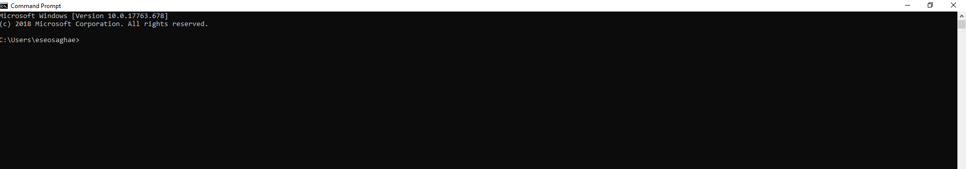
Command Line Example

I decided to develop with the Anaconda environment for Python. The steps for downloading and running Anaconda can be a bit confusing if you do not have previous experience with a command line. A command line is the space to the right of the command prompt on an all-text display mode on a computer monitor (usually a CRT or LCD panel) in which a user enters commands and data. Commands are generally issued by typing them in at the command line and then pressing the ENTER key, which passes them to the shell. For someone completely new to coding though, there are various tutorials and online resources that are instruction based. I will layout the process that I used to get my development environment setup:

Download the Anaconda package through here.

When the installer gives you the option to add this to your environment path be sure to do so. It is important for later interactions with your computer’s command line. 

Use the following conda command in your command line when Anaconda is installed:

conda install jupyter 

Once this command is entered, your computer will unzip the jupyter notebook package from the web. A jupyter notebook is where one can place their Python code. It can also be executed and tested within this environment. It is an awesome tool for developing.

Use the following conda command in your command line after completing the previous installation:

conda install pillow

Once this command is entered, your computer will unzip the pillow package from the web. The pillow package is a great package for Python because it imports functions that are specific to image processing techniques. Once those installations are done, open a new command line and type in the following command:

jupyter notebook

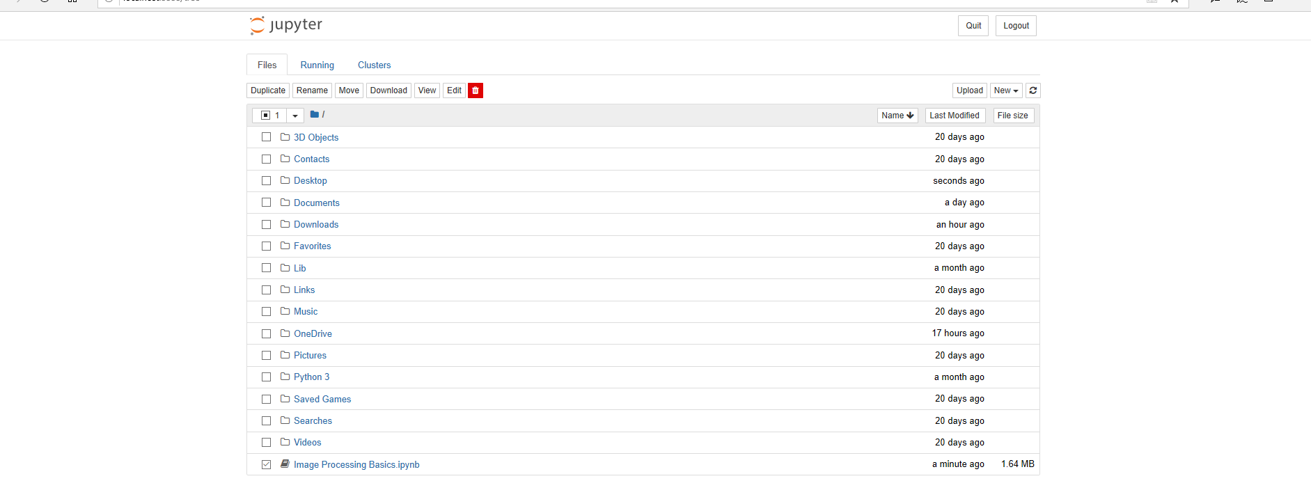
Jupyter First Glance

This will open up a jupyter notebook environment within one of your browser tabs automatically. From there we are now able to start coding and have some fun. There is a button on the upper right hand corner that says new. Click this and press Python 3 for the ability to make a file for developing. The initial popup window should correspond to how your desktop environment is setup in terms of files. 

Now that we have all of this setup, please take a look at this online tutorial here. In this tutorial it is one should copy and type all of the text that appears within the code posted. Without exact formatting, various errors may pop up as you run your program. This is the more challenging part of programming. Being able to spot errors and bugs when we are creating projects is the essence of a succinct programmer. There will also be various items, words, and functions that seem complex. It is important for one to learn everything that seems foreign to them if they want to become an excellent programmer. 

Antialiasing Example

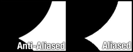
I myself had no real understanding of the word antialiasing. It is something I have seen before in my camera settings of a DSLR I use, and I have seen it within programs such as Photoshop, but I really did not understand what it was. Once I saw it in the context of code, I really had to understand what it meant. In the particular code snippet I copied from the tutorial, the goal was to create images that were at a certain size and shape. In order for images to be compressed, antialiasing is an important factor. Antialiasing is a technique used to add greater realism to a digital image by smoothing jagged edges on curved lines and diagonals. This is a computer graphics technique that allows for sharper resolutions for a photo based on precise geometry. Some of the “imperfections” of an image may be distorted or destroyed due to this. I am certain that in order to do processing such as photogrammetry and image stitching, a computer would have to have exact geometries that can be added together to form a 3D image. This causes the 3D image to have less precision overall in terms of actual dimensions. I wonder what is the margin of error for a 3D image when photogrammetry techniques are accounting for antialiasing. 

Lastly, I learned about an alpha channel. Alpha channels are color components that represent the degree of transparency (or opacity) of a color (i.e., the red, green and blue channels). They are used to determine how a pixel is rendered when blended with another. It now begs the question of how precise are metrology and laser scanning devices in terms of picking up color. These are follow up questions I will be researching more in depth.

Overall, this is the first step into the world of image processing. I am excited to continue research as well as build out fun projects that will show off this field a bit more.

The post What is Metrology Part 16: Introductory Coding appeared first on 3DPrint.com | The Voice of 3D Printing / Additive Manufacturing.

What is Metrology Part 14: Image Restoration

Art Restoration and 3D Printing

Through this metrology series, I hope readers are making this realization: We as humans have faulty perception, and we try to understand our world as precisely as we can. The tools we use to measure items within our world are prone to error, but they do the best they can to reveal the essence of reality. The common adage is that a picture says a thousand words. If one has a blurry or weak picture, the words said are mostly confusing. Devices that take images can be used for metrology purposes as we have discussed earlier. The data that we capture in forms of images is necessary for high resolution and precise metrology methods. How do we make sure that images are giving us words of clarity vs. confusion?

Image restoration is the operation of taking a corrupt or noisy image and estimating the clean, original image. Corruption may come in many forms such as motion blur, noise, and camera misfocus. Image restoration is different from image enhancement in that the latter is designed to emphasize features of the image that make the image more pleasing to the observer, but not necessarily to produce realistic data from a scientific point of view.

Certain industries are heavily reliant on imaging. An example of the interdisciplinary nature of imaging and metrology is found in the medical sector. Biomedical imaging techniques need to be extremely precise for accurate measurements of internal organs and structures. Size, dimensionality, and volume are items that need high precision due to their affect on human life. Without proper images of these items, doctors and physicians would have a difficult time in giving proper diagnoses. Another important caveat to remember is the ability to replicate these structures through the use of 3D printing. Without accurately measured dimensions from 2D images, there would be a lack of precision within larger 3D models based off of these 2D images. We have talked about image stitching and 3D reconstruction previously. This is especially important within the medical field in the creation of 3D printed phantoms.

One can apply the same concept and thought process to the automotive industry. The automotive industry is all about standardization and replicability. There needs to be a semi-autonomous workflow ingrained within the production line of a vehicle. 3D scans are taken of larger parts that have been fabricated. With these original scans, replicability within production is possible. There still lies a problem of precision within an image. There are a lot of variables that may cause a 3D scan to be unreliable. These issues include reflective or shiny objects, objects with contoured surfaces, soft surfaced objects, varying light color, opaque surfaces, as well as matte finishes or objects. It is obligatory that a 3D scan is done in an environment with great lighting. With all of these issues, image restoration is essential with any scan because it is nearly impossible to have a perfect image or scan. Within the automotive industry, the previous problems are very apparent when scanning the surface of an automotive part. 

There are 4 major methods to image restoration that I will highlight here, but will expand upon within further articles.

Inverse Filtering

Inverse filtering is a method from signal processing. For a filter g, an inverse filter h is one that where the sequence of applying g then h to a signal results in the original signal. Software or electronic inverse filters are often used to compensate for the effect of unwanted environmental filtering of signals. Within inverse filtering there is typically two methodologies or approaches taken: thresholding and iterative methods. The point of this method is to essentially correct an image through a two way filter method. Hypothetically if an image is perfect, there will be no visible difference. The filters applied will correct any errors within an image though.

Wiener Filter

In signal processing, the Wiener filter is a filter used to produce an estimate of a desired or targeted random process through linear time-invariant filtering of an observed noisy process, assuming certain conditions are constant such as known stationary signal and noise spectra, and additive noise. This is a method that is focused on statistical filtering. This necessitates time-invariance because adding time into this process will ultimately cause a lot of errors. 

Wavelet-based image restoration

Wavelet-based image restoration is applying mathematical methods that allow for an image and its data to be compressed. With this compression, the ability to process and manipulate an image becomes a bit more manageable. Transient signals are best for this type of method. A transient signal refers to a short-lived signal. The source of the transient energy may be an internal event or a nearby event. The energy then couples to other parts of the system, typically appearing as a short burst of oscillation. This is seen in our readily available ability to capture a picture or image within a specific time frame. 


Blind Deconvolution

Blind deconvolution is a technique that permits recovery of the target scene from a single or set of “blurred” images in the presence of a poorly determined or unknown point spread function(PSF). The point spread function (PSF) describes the response of an imaging system to a point source or point object. A more general term for the PSF is a system’s impulse response, the PSF being the impulse response of a focused optical system. Regular linear and non-linear deconvolution techniques utilize a known PSF. For blind deconvolution, the PSF is estimated from the image or image set, allowing the deconvolution to be performed. 

We will be taking a deeper dive into this subject matter soon. As one can tell, there lies a vast amount of information and interesting technology and knowledge to be further understood. Through writing and experimentation with code, hopefully, I can show these things as well. 

The post What is Metrology Part 14: Image Restoration appeared first on 3DPrint.com | The Voice of 3D Printing / Additive Manufacturing.

What is Metrology Part 12: 3D Reconstruction

3D Reconstruction

In our previous article we outlined the basis of most applications within computer vision. It is a vast and large field. It has a lot of intersectionality with 3D technology and the future of 3D printing as well as metrology. The field of 3D imaging in general takes a wide skill set in general and that is exciting. In this article we will talk about a specific realm within 3D metrology and machine vision and computer vision. This realm is known as 3D reconstruction.

3D reconstruction is the process of capturing the shape and appearance of real objects. This process can be accomplished either by active or passive methods. If the model is allowed to change its shape in time, this can be referred to as non-rigid or spatio-temporal reconstruction. Spatio-temporal reconstruction refers to 4D reconstruction as it is adding the 4th element of time into creating an object (x-position, y-position, z-position, and time). 

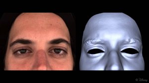
Spatio-temporal reconstruction of eyelids

2D digital image acquisition is the typical information source of 3D reconstruction. 3D reconstruction is based on multiple images, and it may use only one image in some cases. There are various methods for image acquisition that depend on the occasions and purposes of an application. Visual disparity, illumination, performance of the camera, and the scenario should be considered when attempting to do a 3D reconstruction. 

In terms of metrology, the objects used to measure the 3 dimensional object as a whole include a camera as well as a data interpreter such as a computer. The camera will take 2D images in terms of digital image data. This is referred to as a monocular cue method for data collection. Monocular cues typically include a singular viewport, such as a camera with one lense. Monocular cues methods refer to using one or more images from one viewpoint to create a 3D construction. It makes use of 2D characteristics (e.g. Silhouettes, shading and texture) to measure 3D shape, and that’s why it is also named Shape-From-X, where X can be silhouettes, shading, texture, etc. 3D reconstruction through monocular cues is simple and quick, and usually one digital image so it requires only one camera. Stereo correspondence is a fairly complex problem that this method tries to avoid. 

Correspondence Problem

Stereo correspondence refers to correspondence problem of 3D reconstruction. The correspondence problem refers to the problem of realizing which parts of an image correspond to certain parts of a different image. Differences are due to movement of a camera, time changing, and/or movement of objects in a photo.

When we have two or more images of the same 3D scene, taken from different points of view, the correspondence problem refers to how we find a set of points in one image that are classified as the same points in another image. Points or features in one image are matched with the matching points or features in another image. The images can be taken from a different point of view, at different times, or with objects in the scene in general motion relative to a camera(s). 

This problem of stereo correspondence is most prevalent when multiple devices are used to capture images. If two photographers take an image of a scene, it is nearly impossible to have them sync up their 3D data from the 2D forms that they took. One frame of reference may include an extreme amount of information that does not sync with a frame of reference that may be only a couple meters away. 

A typical application of the correspondence problem is found in panorama creation or image stitching. When two or more images that have a small overlap are stitched into a larger image this problem is apparent. It is necessary to be able to identify a set of corresponding points in a pair of images in order to calculate the transformation of one image to stitch it onto the other image.

In our next article we will be analyzing a particular method within measurement that deals with this problem and the advanced physics behind it.

The post What is Metrology Part 12: 3D Reconstruction appeared first on 3DPrint.com | The Voice of 3D Printing / Additive Manufacturing.