BCN3D Testes Chemical Resistance of Eight Common 3D Printing Materials

A material’s ability to resist degradation, erosion, or impregnation from contact with liquids, solids, or vapors of a different nature, like chemical solvents, acids, and bases, is known as chemical resistance, and it’s pretty important to achieving successful parts. When you’re choosing the materials you want to use for 3D printed end-use applications, especially for industrial purposes, you should know each element’s chemical resistance. Some 3D printing materials can swell when exposed to the liquids or vapors of solvents, like alcohols, esters, ketones, fuel, brake fluid, motor oil, and various mixtures of mineral and synthetic hydrocarbons, which changes the end part’s mechanical properties and shape. Industrial parts need to be able to hold up well under contact with these kinds of corrosive products, so filaments should be chosen wisely.

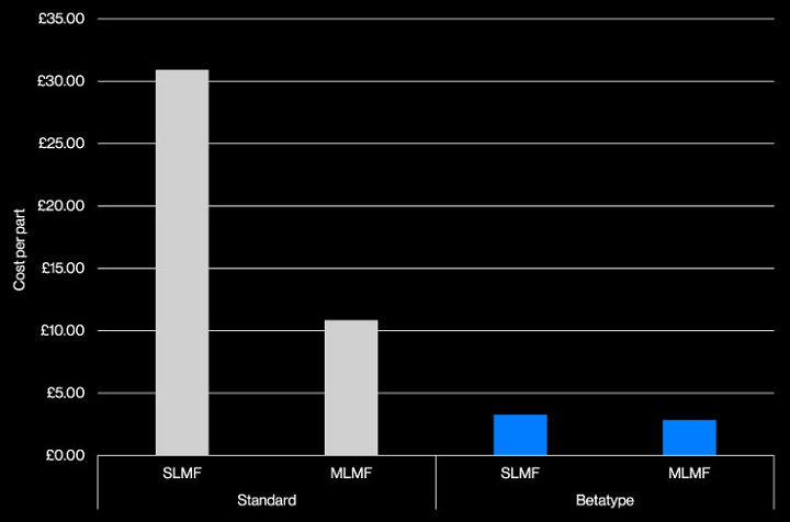
Barcelona-based desktop 3D printer manufacturer BCN3D Technologies wanted to investigate the behavior of its main filaments when they came in contact with corrosive products, in order to better inform customers on which materials should be used for specific applications. So the company put eight of its materials to the test by pitting them against an organic solvent’s chemical attack.

“This experiment was carried out by partially immersing these 3D printed parts in a small volume of organic solvent,” BCN3D wrote. “The corrosive agent chosen was Nitro-P, which is used to dilute paints and is very aggressive. To maximize the damage, the 3D printed parts were immersed in the solvent for a period of 24 hours, and their change in shape and properties was monitored by a timelapse camera followed by a visual and physical evaluation.”

The team wanted to simulate the effect caused on a 3D printed object when a solvent is accidentally splashed on it – quite a common occurrence in workshop and factory environments. The goal was to show users how important it is to choose the right filament for the end application, and risk of chemical exposure, so that the final product is safe and durable. The same print settings were used to fabricate parts with a shape that was designed to “favor the material degradation” out of the following filaments:

  • Polylactic acid (PLA)
  • Polyethylene terephthalate – glycol (PET-G)
  • Acrylonitrile butadiene styrene (ABS)
  • Thermoplastic polyurethane (TPU)
  • Polyamide (PA)
  • Polypropylene (PP)
  • High Temperature Polyamide carbon fiber reinforced (PAHT CF15)
  • Polypropylene glass fiber reinforced (PP GF30)

BCN3D hypothesized that the parts 3D printed out of PP would come out fully intact, while the PLA and ABS parts would be most affected by the solvent and hygroscopic materials (absorbing moisture from the air), like TPU and PA, would likely increase in volume.

So, what ended up happening?

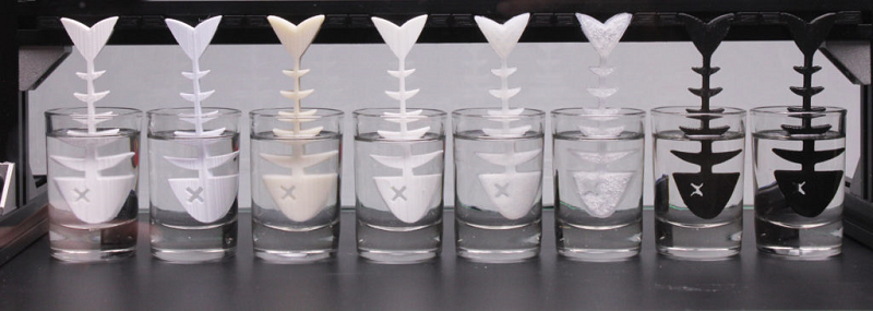
They were right about the PLA and the ABS – the geometry of the 3D printed PLA part was totally, and quickly, changed by the solvent. The layers were separated, which broke the part, and the surface finish dimmed from bright to matte. Additionally, its thickness increased by 60%. The thickness of the ABS was only reduced by 15%, but the layers still separated, making the part viscous where it was submerged. Degradation was constant, causing the ABS to dissolve, and it was the only sample that changed above the level of the liquid: the evaporated solvent caused it to become brighter.

TPU sample

The TPU sample absorbed the solvent quickly, which caused its thickness to increase by a whopping 150%. BCN3D explained that the absorption generated “delaminations in the submerged part of the model as a result of the increase in volume due to the polarity of the solvent and the absorption capacity of TPU,” but once the absorbed solvent evaporated, the part “recovered its original properties,” which led the team to believe the results were “a phenomenon of physical adsorption without dissolution of the polymer.”

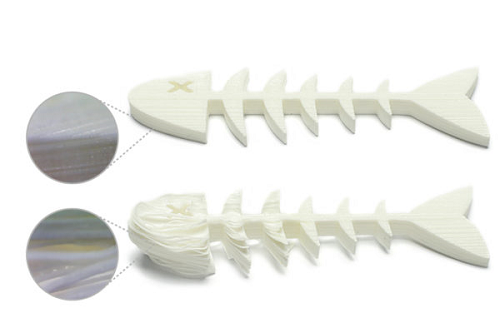
The thickness of the PA sample increased by 10%, and the effects of the solvent also caused it to gain flexibility. The PAHT CF15 also increased its flexibility and thickness in the solvent, but there was no dissolution of the material in the solution. This one swelled a little, but held on to its resistance and original shape.

The surface finish of the PET-G sample lost its brightness, though the solvent smoothed and softened its surface. The layers were slightly concealed due to the superficial polishing caused by the solvent, and the thickness and flexibility both increased. But while it lost most of its rigidity and resistance, the part did remain in its general shape.

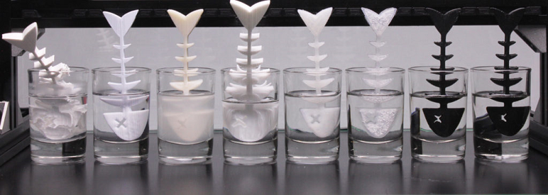
Neither the PP nor the PP GF30 were terribly affected by the solvent during the test, showing no change in mechanical behavior or variations of either an aesthetic or dimensional sort. The PA did swell a bit, but managed to keep most of its original resistance and shape. The experiment shows that these two materials are ideal for 3D printed industrial applications where parts need to hold up under contact with other corrosive substances.

Discuss this story and other 3D printing topics at 3DPrintBoard.com or share your thoughts below.

The post BCN3D Testes Chemical Resistance of Eight Common 3D Printing Materials appeared first on 3DPrint.com | The Voice of 3D Printing / Additive Manufacturing.

Betatype Case Study Illustrates Cost and Time Savings of Using 3D Printing to Fabricate Automotive Components

When it comes to industrial 3D printing for automotive applications, London-based Betatype is building up considerable expertise. The 3D printing company was founded in 2012, and works with its customers to deliver functional, 3D printed components. Betatype built a data processing platform called Engine to help manage and control multi-scale design; the platform maximizes the ability of 3D printing to provide control in one process over material, shape, and structure.

Some of the benefits provided by 3D printing include high cost-per-part, productivity, and volume, especially when it comes to using metals. Betatype recently completed a case study that demonstrates how the advantages of metal 3D printing can be properly leveraged for applications in automotive parts production. It focuses on Betatype’s use of laser powder bed fusion (LPBF, also called Powder Bed Fusion, DMLS and SLM) 3D printing and optimization technology to, as the case study puts it, challenge “the current status quo” by producing 384 qualified metal parts in one build, which helped lower both lead time and cost per part.

“When it comes to automotive and other consumer-facing industries focused on producing high volumes of parts at low costs, the current generation of Additive Manufacturing (AM) processes is generally considered incapable of meeting these needs,” Betatype explained in its study.

“The key to making AM productive enough for wider adoption across these high-volume industries, however, lies in process economics – choosing the most effective manufacturing process for each part. Combining these principles with Betatype’s knowledge of the limits of additive – as well as how and when to push them – together with the company’s powerful optimisation technology, supports customers with the design and production of parts that not only perform better, but that are economically viable against existing mass production technologies.”

Production build of automotive LED heatsinks by Progressive Technology on an EOS M280.

You’ll often hear people in the 3D printing industry saying that one of the benefits of the technology is its ability to offer greater design freedom than what you’d find in more conventional manufacturing process. While this is true – 3D printing can be used to produce some pretty complex geometry – that doesn’t mean it’s without its own problems. It’s necessary to understand these constraints in order to find applications that can fit with the technology, and be used in high volume manufacturing as well.

Processes like die casting are capable of creating millions of components a year. 3D printing is valuable due to its capability of using the least amount of material to provide geometrically complex parts. Often 3D printing just doesn’t have the manufacturing volume or part cost to be an economical choice. But, this may not be the case for long.

According to the case study they looked at, “how it is possible to combine the innate geometric capabilities of AM with increased production volumes of cost-effective parts and improved performance” The team looked at “the Automotive industry’s switch to the use of LED headlights, which brings with it new challenges in thermal management.”

Most LED headlights need larger heatsinks, which are typically actively cooled. Betatype realized that the geometry of these metal parts would make them a good candidate for metal 3D printing, which is able to combine several manufacturing processes into just one production technique.


Betatype realized that LPBF would be ideal during the component’s initial design stage, and so was able to design the component with in-built support features. This made it possible to stack multiple headlight parts without requiring any additional supports; in addition, the company maintains that completed parts could be snapped apart by hand without any other post-processing required. This claim is something that we are highly skeptical about. No destressing or tumbling, shot peening, HIP or other processes usually result in parts that look different from the ones in the images given to us.

[Image: EOS]

Depending on part geometry it can be difficult to achieve full stacking with LPBF 3D printing. This is largely due to thermal stresses placed on parts and supports. Betatype designed the part in such a way as to decrease these stresses. This is what allowed Betatype to nest a series of heatsinks in order to maximize build volume and produce nearly 400 parts in one build envelope using an EOS M 280 3D printer owned by Progressive Technology.

“Through specific control parameters, the exposure of the part in each layer to a single toolpath where the laser effectively melted the part was reduced significantly, with minimal delays in between.”

13 x the productivity per system. Estimated Number of Parts per Machine per Year/Model built on build times provided by Progressive Technology for SLMF system (EOS M 280) and Renishaw AMPD for MLMF system (RenAM 500Q).

One of the large drivers in part cost is equipment amortization, and it’s important to lower build time in order to make parts more cost-effective. By using LPBF 3D printing and its own process IP and optimization algorithms, Betatype claims to have reduced cost-per-part from over $40 to less than $4, and lower the build time from one hour to less than five minutes per part – ten times faster than what a standard build processor is capable of performing. This would be a huge leap in capability for metal printing if these cost estimates stack up.

On single laser systems, like the EOS M 280 and Renishaw’s RenAM 500M, Betatype says that lowered the build time for all 384 parts from 444 hours to less than 30 hours; this number went down even further, to less than 19 hours, by using new multi-laser systems like the SLM Solutions 500 and the RenAM 500Q.

Up to 90% reduction in part cost. Estimated Cost per Part / Model built on build times provided by Progressive Technology for SLMF system (EOS M 280) and Renishaw AMPD for MLMF system (RenAM 500Q).

Betatype’s claims that their customer was able to achieve a productivity gain of 19 times the old figure per system in a year  – going from 7,055 parts to a total of 135,168.

The case study concludes, “With an installation of 7 machines running this optimised process, volumes can approach 1 million parts per year — parts that are more functional and more cost-effective.”

It always good to show performance that is a step change ahead of what everyone thought possible. It is also significant that companies are making detailed case studies and verifiable claims as to output and yield. Betatype’s Case Study shows very promising numbers and we hope that productivity can indeed reach these heights with their technology.

Discuss this story and other 3D printing topics at 3DPrintBoard.com or share your thoughts in the Facebook comments below.

[Images provided by Betatype unless otherwise noted]

INTAMSYS Launches Jigs and Fixtures-Themed Industrial 3D Printing Global Competition

Shanghai-based 3D printer manufacturer INTAMSYS, which stands for Intelligent Additive Manufacturing Systems, often makes the headlines for its reliable, industrial-grade FUNMAT 3D printers‘ capabilities in providing 3D printing solutions with tough, functional, high-performance, and high-temperature materials, such as PEEK and PEKK, ULTEM 1010 and ULTEM 9085, PSU, and PPSU, thanks to heated build plates, high-temperature nozzles, and breakthrough thermal technologies on active heated chambers.

INTAMSYS, which partners with many well-known companies around the world, operates several manufacturing and research facilities, and runs its own 3D printing service, provides solutions for many applications, ranging from medical, as in the case of this innovative PEEK knee brace, to industrial, such as making end-use parts, tools, jigs, and fixtures. The company is focusing on the latter for an exciting new event – INTAMSYS is hosting its very first competition this summer.

The Industrial 3D Printing Global Competition for Industry 4.0, focusing on a theme of Jigs and Fixtures, has officially launched, with entries being accepted up until August 31st, 2018. Over $10,000 in cash and prizes are at stake, so you should start preparing your entry soon.

Chun Pin Lim, the Marketing Director of INTAMSYS, said, “During our business visits in the USA, Europe and China, we’ve learned first-hand from our customers and partners that 3D printed jigs and fixtures in polycarbonate, nylon and PEEK have significantly improved lead time, worker safety and costs on their production floors.”

The aim of INTAMSYS’ new Industrial 3D Printing Global Competition is to identify and reward participants who can, as the company puts it, “best exemplify” the use of 3D printing solutions in terms of manufacturing jigs and fixtures, in order to achieve the best possible manufacturing lead time and cost savings.

This competition is open to any and all organizations, companies, and research and educational institutions around the world that currently use 3D printing to manufacture jigs and fixtures. When entering, participants must submit the following:

  • Full name of entity
  • First and last name(s) of team’s main contact person
  • Email and phone number, for award notification purposes only
  • Full address
  • Main purposes of the 3D printed jig or fixture and its dimensions in millimeters
  • Types of material used to 3D print fig or fixture

Competition entries must also include details regarding the cost, durability, lead time, and any other benefits of 3D printing the jig or fixture when compared to previously used fabrication methods. Additionally, entrants must include three photos – one of the jig or fixture being 3D printed, a photo of the fully printed object, and one of it while being used; check out this link to see sample photos.

The three competition winners will be announced on this site, and informed via either email or phone, on September 14th, 2018. The second runner-up will receive US$1,000, while the first runner-up will be awarded a prize of $2,000.

The winner of the competition will receive the grand prize: $2,000, a FUNMAT HT 3D printer, and 2 kg each of INTAMSYS nylon, PEEK, and polycarbonate filaments – all together, this prize is worth a total of $10,000, including global shipping costs for the 3D printer and filaments, which INTAMSYS will provide. Prizes are not exchangeable.

What do you think of this news? Discuss advanced manufacturing competitions, challenges, and contests, and other 3D printing topics, at 3DPrintBoard.com or share your thoughts in the Facebook comments below.