Beijing University of Chemical Technology: 3D Printed HA/PCL Tissue Engineering Scaffolds

3D printed bone scaffolds used for tissue engineering purposes need to have a good amount of mechanical strength, since the scaffold needs to be able to provide support for the tissue. As bone scaffolds also require the correct pore structure to help provide a good environment for the differentiation, proliferation, and repairing of damaged tissue cells, bioactive materials, such as polycaprolactone (PCL) and hydroxyapatite (HA), are needed.

Researchers Zhiwei Jiao, Bin Luo, Shengyi Xiang, Haopeng Ma, Yuan Yu, and Weimin Yang, from the Beijing University of Chemical Technology (BUCT), published a paper, titled “3D printing of HA / PCL composite tissue engineering scaffolds,” about their work constructing nano-HA/PCL and micro-HA/PCL tissue engineering scaffolds using the melt differential FDM 3D printer they developed.

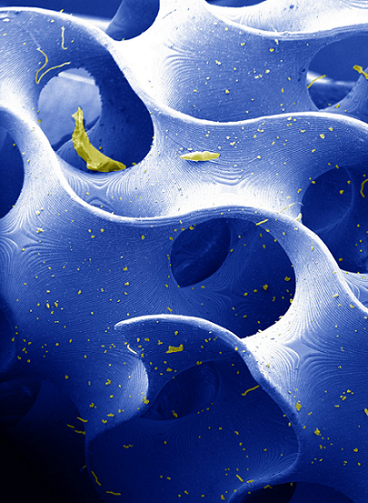
The abstract reads, “Here, the internal structure and mechanical properties of the hydroxyapatite/polycaprolactone scaffolds, prepared by fused deposition modeling (FDM) technique, were explored. Using hydroxyapatite (HA) and polycaprolactone (PCL) as raw materials, nano-HA/PCL and micro-HA/PCL that composite with 20 wt% HA were prepared by melt blending technology, and HA/PCL composite tissue engineering scaffolds were prepared by self-developed melt differential FDM 3D printer. From the observation under microscope, it was found that the prepared nano-HA/PCL and micro-HA/PCL tissue engineering scaffolds have uniformly distributed and interconnected nearly rectangular pores. By observing the cross-sectional view of the nano-HA/PCL scaffold and the micro-HA/PCL scaffold, it is known that the HA particles in the nano-HA/PCL scaffold are evenly distributed and the HA particles in the micro-HA/PCL scaffold are agglomerated, which attribute nano-HA/PCL scaffolds with higher tensile strength and flexural strength than the micro-HA/PCL scaffolds. The tensile strength and flexural strength of the nano-HA/PCL specimens were 23.29 MPa and 21.39 MPa, respectively, which were 26.0% and 33.1% higher than those of the pure PCL specimens. Therefore, the bioactive nano-HA/PCL composite scaffolds prepared by melt differential FDM 3D printers should have broader application prospects in bone tissue engineering.”

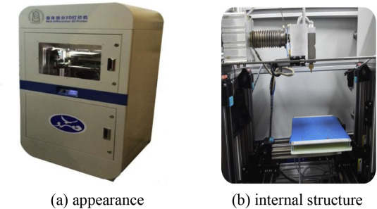
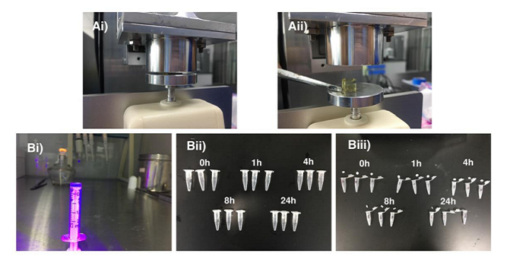
Melt differential 3D printer.

PCL is biocompatible, biodegradable, and has shape retention properties, which is why it’s often used to fabricate stents. But on the other hand, due to an insufficient amount of bioactivity, the material is not great for use in bone tissue engineering. HA, which has been used successfully as a bone substitute material, has plenty of bioactivity, which is why combining it with PCL can work for bone tissue engineering scaffolds.

“On the whole, the existing tissue engineering scaffolds preparation process have problems of low HA content, easy agglomeration, low stent strength, and single printing material,” the researchers explained.

“The HA/PCL composite particles are used as printing materials, and the mechanical properties and structural characteristics of the two tissue engineering scaffolds are compared and analyzed. The raw material of the melt differential 3D printer is pellets, which eliminates the step of drawing compared to a conventional FDM type 3D printer. The 3D printer is melt-extruded with a screw, and a micro-screw is used for conveying and building pressure. At the same time, precise measurement is performed by a valve control system. This printing method shows advantages in simple preparation process of the composite material, higher degree of freedom in material selection, simple printing process, and shorter preparation cycle of tissue engineering scaffolds.”

The team mixed PCL particles and HA powder together to make the scaffolds. Their melt differential 3D printer uses pellets, and features a fixed nozzle with a platform that moves in three directions. A twin-screw extrusion granulator was used to prepare the PCL material, and the melt differential 3D printer fabricated the tissue engineering scaffolds out of the nano-HA/PCL and micro-HA/PCL composite particles.

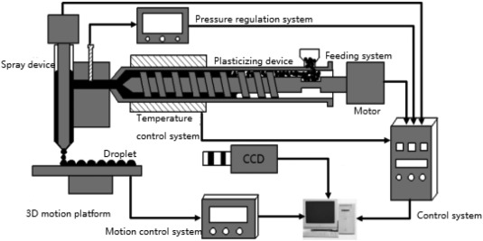
The working principle diagram of the polymer melt differential 3D printer.

A microcomputer-controlled electronic universal testing machine was used to test the scaffolds’ bending and tensile properties. A scanning electron microscope was used to observe the micro-HA particle size, as well as the scaffolds’ cross section, while an optical microscope was used to observe their surface structure and a transmission microscope was used to look at the nano-HA particles’ particle diameter and morphology. The scaffold material’s crystallization properties were analyzed using a differential thermal analyzer.

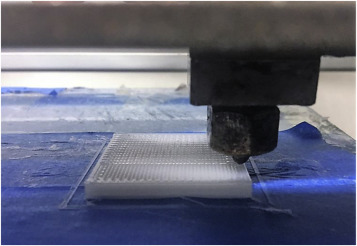
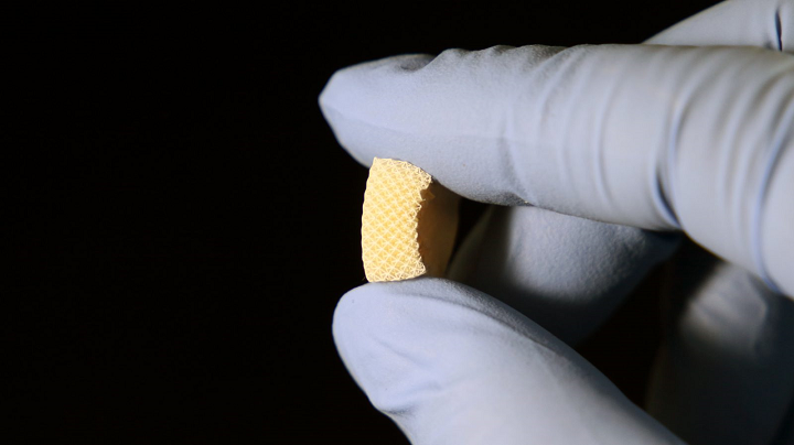
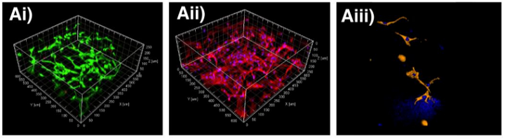
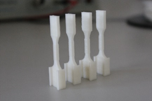
3D printing tissue engineering scaffolds.

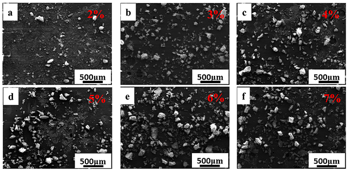
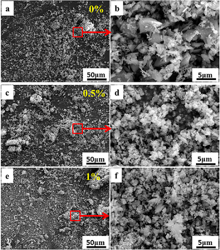
Testing showed that the micro-HA was spherical, with a 5–40 μm diameter, and contained some irregularly-shaped debris. The nano-HA was rod-shaped, with a 20–150 nm length.

The crystallization peak temperature of the HA/PCL composites was higher than pure PCL material, because adding HA caused its molecular chain to form a nucleate after absorbing on the HA’s surface. Additionally, adding HA to pure PCL increased the material’s melting temperature, as the latter material had crystals “of varying degrees of perfection.”

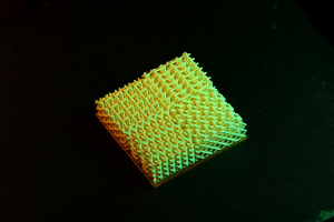
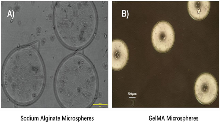
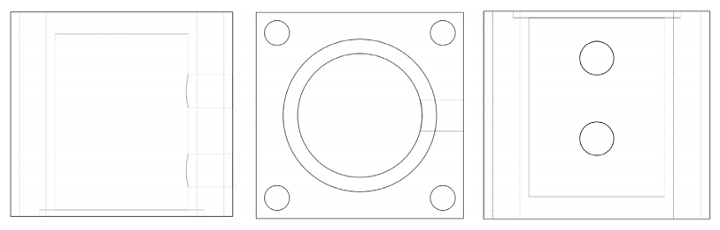
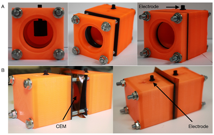
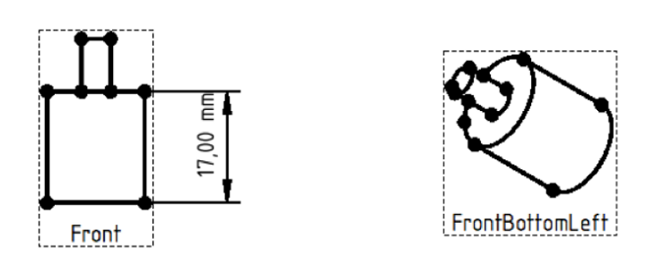
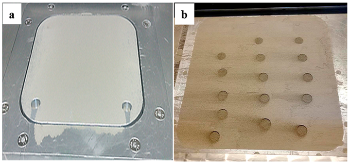
The nano-HA/PCL and micro-HA/PCL tissue engineering scaffolds “could form a pre-designed pore structure and the pores were connected to each other,” which is seen in the image below.

“…the micro-HA/PCL and the nano-HA/PCL composite tissue engineering scaffolds can form a three-dimensional pore structure with uniform distribution and approximately rectangular shape.”

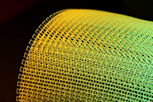
External views of micro-HA/PCL and nano-HA/PCL composite tissue engineering scaffolds.

These rectangular pores, with a 100-500 μm length and width, are good news for cell adhesion and proliferation, and the fact that they’re interconnected is positive for nutrient supply.

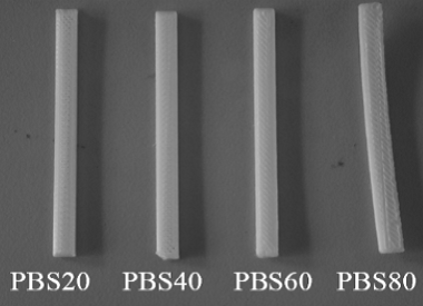
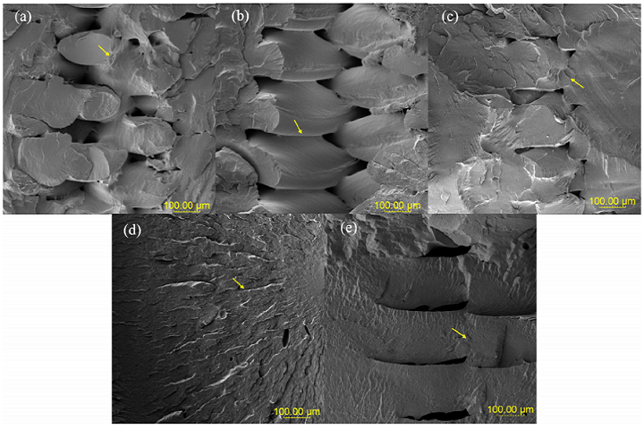
As for mechanical properties, the nano-HA/PCL specimens had the highest tensile and bending strengths – between 25 and 35% higher than the pure PCL. The micro-HA/PCL specimens had higher tensile and flexural strengths than the PCL, but the nano-HA/PCL was stronger than the micro-HA/PCL, because the HA’s modulus is higher than the PCL’s.

“In addition, nano-HA was more evenly distributed in the composite, while micro-HA had obvious agglomeration in the composite, so the tensile strength and flexural strength of nano-HA/PCL specimens were higher than that of micro-HA/PCL specimens,” the researchers wrote.

Finally, the pore structure of the nano-HA/PCL and micro-HA/PCL tissue engineering scaffolds offered a favorable environment for the discharge of cellular metabolic waste, in addition to facilitating nutrient transport and blood vessel growth. The researchers concluded that their 3D printed composite scaffolds had more potential applications in bone tissue engineering.

Discuss this and other 3D printing topics at 3DPrintBoard.com or share your thoughts below.

The post Beijing University of Chemical Technology: 3D Printed HA/PCL Tissue Engineering Scaffolds appeared first on 3DPrint.com | The Voice of 3D Printing / Additive Manufacturing.

Interview with Godwin Izibilli on 3D Printing in Nigeria

Nigeria is an African country well known for high profile academics and a large base of entrepreneurs. How is Africa’s most populous country utilizing these twin resources for 3D Printing? We interviewed Godwin Izibilli of CAD Works to give you insights into 3D printing in Nigeria.

Godwin Izibilli

Who are you and what is CAD Works? 

I am presently the head of the operation at CAD WORKS limited. I did my engineering degree at the University of Benin, Benin-city and graduated after which I worked in the vehicle assembly unit of KIA Motors (that is after the one-year mandatory National Service in Kwara-State, Nigeria). And also consult for Prightle solutions on a part-time basis.

Cad Works Limited is an engineering company that specializes in various engineering design, CAD consulting, Laser Scanning, and 3D printing services which could be in form of setting up 3D printing Laboratory, 3D printer sales and repairs, 3D printing service, part designs, and training on Engineering Design. We are presently located in Nigeria and Ghana and have carried out projects for companies like Chevron Nigeria Limited, Mobil Nigeria limited, Global Ocean and many more. We have recently done several presentations/expo for the Association of professional women Engineers in Nigeria, Nigeria Society of Engineers (Victoria Island), DigiFab Conference, Girls Hackathon for Justice, and for the sake introduction, we are having a 3D printing conference for the whole of Africa. It is called “Future of Additive Manufacturing in Africa.”

What are some of the projects that you do in 3D printing and Additive Manufacturing?

We recently worked on an oil facility that did not have a 3D model of the entire facility. So, our team did the laser scanning of the facility and produced the 3D model of the facility after which we used the 3D model to 3D print a model of the facility.

3D printed oil facility model

Also, we 3D modeled and 3D printed a large number of key holders for a church as a souvenir during their Christmas celebration.

3D printed church key holders

Give us a brief description of the 3D Printing landscape in Nigeria?

The Nigerian environment is a dicey one in the sense that people who are aware of the technology are fascinated by it, but are not willing to take steps. Some factors which are negatively impacting this include the cost. Also, because of the unavailability of metal 3D printers in the country, big players do not stimulate that development. But some schools are gradually taking it into their extra-curricular activities. Individuals who want to print products, want the finishing to be as if the production process was like that of an injection molding process. This is holding us back. But the market is growing, people are seeing the need. It would be a boom if the government could either train masses of people or create centers where individuals can print at a much lower cost and still have a quality product.

Demonstrating 3D printing to students

You have recently published the first edition of your 3D Printing magazine entitled ‘Advanced Manufacturing’ and of particular interest is the section ‘Why 3D printing matters to Africa’.

That article, we hope could cause an awakening that this technology is made for us and that several persons are already doing something great with it. Take, for example, some time ago, some Togolese created a 3D printer from recycled materials! This I believe should be encouraged as I know that since most things that pertain to this technology are open source (that is from models to parameters, to experiences), we Africans, can utilize the opportunity to grow somethings for ourselves and become innovators! Like the rest of the world.

Do you see any possible financial support in developing 3D printing in Africa considering that it’s one of the challenges in promoting the technology?

It all depends in which direction they do this. Nobody I believe would invest in something unless the person has something to benefit from it. Unless it’s just for humanitarian purposes. To this end, I feel we only within Africa through the government seeing the need, or individuals who have technology inclined business and as such would be willing to bring out resources gotten from another venture, and put it into 3D Printing. But the difficult thing about it is that, as the usefulness of the 3D Printing technology expands, and as the time to print/volume of prints increases, individuals and bodies (which also includes schools of different cadres) would embrace it and include it to their everyday lives. As in the case of South Africa, the government saw the need and invested in the technology. I believe that other countries would with time, do the same and encourage the young ones to become beneficiaries of this technology.

The post Interview with Godwin Izibilli on 3D Printing in Nigeria appeared first on 3DPrint.com | The Voice of 3D Printing / Additive Manufacturing.

Virginia Tech Researchers Using a New Method to Create 3D Printed Piezoelectric Materials

A 3D printed, flexible energy harvester [Image: H. Cui of the Zheng Lab]

Originally discovered in the 19th century, piezoelectric materials, which convert stress and strain into electric charges, are in everything from musical greeting cards to cell phones. Piezoelectricity is electricity that results from pressure, and thanks to a new 3D printing method created by a group of researchers and mechanical engineers from Virginia Tech University, it may be possible to 3D print these types of materials in order to develop things like self-adaptive infrastructures and transducers, tactile sensors, and intelligent materials.

These materials are inherently brittle, as they’re made up of ceramic and crystal. They come in just a few shapes, and can only be manufactured in a clean room, so their potential hasn’t been explore too much, especially not in the 3D printing industry. But Xiaoyu ‘Rayne’ Zheng, a member of the university’s Macromolecules Innovation Institute and an assistant professor of mechanical engineering in the College of Engineering, and the rest of his team determined a new way to 3D print piezoelectric materials so they’re not restricted by shape or size, and can be custom-designed to convert stress, movement, and impact from any direction into electrical energy.

Internal topology of 3D printed piezoelectrics spanning the width of human hair.

The team explains their research further in a paper, titled “Three-dimensional printing of piezoelectric materials with designed anisotropy and directional response,” which was recently published in the Nature Materials journal. Co-authors of the paper are Huachen Cui, Ryan Hensleigh, Desheng Yao, Deepam Maurya, Prashant Kumar, Min Gyu Kang, Shashank Priya, and Zheng.

Zheng, who has experience in 3D printing at both the nanoscale and microscale, and his team created a model that lets them “manipulate and design arbitrary piezoelectric constants,” which ends in the material responding to incoming forces and vibrations and generating, and moving, an electric charge, through a set of 3D printable topologies. This allows users to not only prescribe, but also program, voltage responses to be reversed, magnified, or suppressed in any direction.

“We have developed a design method and printing platform to freely design the sensitivity and operational modes of piezoelectric materials. By programming the 3D active topology, you can achieve pretty much any combination of piezoelectric coefficients within a material, and use them as transducers and sensors that are not only flexible and strong, but also respond to pressure, vibrations and impacts via electric signals that tell the location, magnitude and direction of the impacts within any location of these materials,” Zheng explained.

Natural crystals play a role in the manufacturing of piezoelectrics, as the orientation of atoms are fixed at the atomic level. The researchers created a substitute that mimics the crystal, but at the same time makes it possible to alter the lattice orientation.

“We have synthesized a class of highly sensitive piezoelectric inks that can be sculpted into complex three-dimensional features with ultraviolet light,” Zheng said. “The inks contain highly concentrated piezoelectric nanocrystals bonded with UV-sensitive gels, which form a solution — a milky mixture like melted crystal — that we print with a high-resolution digital light 3D printer.”


The 3D printed piezoelectric materials were demonstrated at a tiny scale, which measures just fractions of the diameter of a single human hair.

“We can tailor the architecture to make them more flexible and use them, for instance, as energy harvesting devices, wrapping them around any arbitrary curvature. We can make them thick, and light, stiff or energy-absorbing,” said Zheng.

“We have a team making them into wearable devices, like rings, insoles, and fitting them into a boxing glove where we will be able to record impact forces and monitor the health of the user.

The material is five times more sensitive than flexible piezoelectric polymers, and it’s possible to tune and produce its shape and stiffness as a block or a thin sheet.

Priya, the Associate VP for Research at Penn State and a former professor of mechanical engineering at Virginia Tech, said, “The ability to achieve the desired mechanical, electrical and thermal properties will significantly reduce the time and effort needed to develop practical materials.”

L-R: Huachen Cui, Desheng Yao, Rayne Zheng, and Ryan Hensleigh

The researchers have kept busy 3D printing the material and demonstrating its applications as smart materials used to harvest mechanical energy, wrap around curved surface, and convert motion. But even beyond consumer electronics and wearables, Zheng believes their work could be used in robotics, tactile sensing, and intelligent infrastructure. Then, structures could be completely made of piezoelectric material, so they can sense, monitor, and locate vibrations, motions, and impacts.

In order to demonstrate their material’s applicability for sensing the locations of dropping impacts, while also absorbing impact energy, the team 3D printed a small smart bridge. Additionally, they created a smart transducer that can convert underwater vibration signals to electric voltages.

“Traditionally, if you wanted to monitor the internal strength of a structure, you would need to have a lot of individual sensors placed all over the structure, each with a number of leads and connectors. Here, the structure itself is the sensor — it can monitor itself,” said Cui, a doctoral student with Zheng.

[Source: Science Daily]

Discuss this and other 3D printing topics at 3DPrintBoard.com or share your thoughts below.

Massachusetts Researchers Develop In-Line Rheometer for FDM 3D Printing

In-line rheometer nozzle design: (a) custom nozzle, (b) load transfer column, [(c) and (d)] load transfer column plus thermocouple inserted into the nozzle pressure port, (e) custom clamps for the load cell, and (f) full assembly.

Rheology is the study of the flow of matter, and the flow rate of 3D printing materials is fairly important when it comes to the final print. According to a pair of researchers from Massachusetts, it’s actually “the most critical material property” in terms of most polymer melt and liquid processing 3D printing processes, like FDM. It can determine the shear rate along the material flow path, influence melt temperature, create important pressure profiles, determine material output and flow rate, and even influence the final material strength and shape.

The researchers, hailing from the University of Massachusetts Lowell and Saint-Gobain Research North America, recently published a paper, titled “In-line rheological monitoring of fused deposition modeling,” about their work developing an in-line rheometer for the FDM process.

Nozzle dimensions measured by x-ray computed tomography.

The abstract reads, “An in-line rheometer has been incorporated into a fused deposition modeling printer for the first time by designing a modified nozzle with a custom pressure transducer and a thermocouple for measuring the processed melt temperature. Additionally, volumetric flow rates and shear rates were monitored by counting the stepper motor pulses as well as the pulses from a custom filament encoder to account for filament slippage and skipped motor steps. The incorporation of the sensors and the design and development of the in-line rheometer are described; and pressures, temperatures, and viscosities within the 3D printing nozzle are presented. The in-line rheometer was validated against traditional, off-line rotational rheology and capillary rheology measurements by analyzing two polymeric materials: polycarbonate and high-impact polystyrene. A variety of rheological corrections were considered for the in-line rheometer, including entrance effects, non-Newtonian corrections, shear heating, pressure effects, and temperature fluctuations/inaccuracies. Excellent agreement was obtained between the in-line and off-line rheometers after applying the most critical corrections, which were found to be entrance effects, non-Newtonian corrections, and temperature inaccuracies. After applying the appropriate corrections, the in-line rheometer provides an accurate viscosity measurement that can be used for real-time monitoring and process control.”

In-line, or on-line, rheometers, are most often validated by applying rheological corrections, then comparing the on-line measurements to the off-line ones. These corrections are important in order to get accurate viscosity measurements, but according to the paper, “in-line rheometers have yet to be incorporated or studied on FDM to confirm the theoretical calculations or to study the influence of rheology on final properties.”

“This article describes the design of the custom pressure transducer and custom nozzle required for the in-line rheometer. The performance of the rheometer is validated against off-line rheological measurements as well as with an in-line comparison to a capillary rheometer. Finally, a variety of rheological corrections are considered and discussed, including end effects, non-Newtonian flow, viscous dissipation, pressure effects, and temperature corrections,” the researchers wrote.

System of sensors, devices, and connections for in-line rheology and process monitoring.

The researchers did analyze viscous dissipation as well, though it was determined to be negligible and no corrections were applied to the data. A LulzBot TAZ 6 3D printer was used, and the researchers developed a new nozzle system, complete with several custom parts, to create the in-line rheometer. Both the load cell clamps and the nozzles were produced from brass castings of lost wax patterns 3D printed by Shapeways, and polycarbonate (PC) and high-impact polystyrene (HIPS) filaments were both analyzed on the in-line rheometer.

CapRheo/FDMRheo joint setup for verifying FDMRheo pressure measurements against a CapRheo pressure transducer.

The researchers validated the in-line FDM rheometer (FDMRheo) by 3D printing into open space with a stationary nozzle raised 30 cm above the build plate. Capillary rheology (CapRheo) and rotational rheology (RotRheo) were both performed for the HIPS and PC materials. The researchers found that the FDMRheo they designed was able to provide very accurate measurements of viscosity.

“The FDMRheo can collect data across a wide range of temperatures and shear rates to generate a successful Cross-WLF model for analyzing continuous viscosity curves as a function of temperature, shear rate, and pressure. The sensor for measuring the filament feed rate as well as the thermocouple for measuring melt temperature were both critical for the deployment and accuracy of the in-line rheometer. Entrance effects were the most significant correction for obtaining an accurate viscosity, so the Bagley correction should be applied to allow the FDMRheo to be used for real-time process control of the FDM process. For example, a control scheme could be developed to optimize the printing speed while maintaining pressures and viscosities within the ideal processing window,” the researchers concluded. “The FDMRheo is suitable for analyzing the viscosity of new, 3D printable materials to more rapidly introduce new materials to the market; the vision is that the rheometer can enable automatic process optimization and quality assurance using physics-based models for weld fusion (i.e., interlayer strength), residual stress, print density, and shrinkage.”

Co-authors of the paper are Timothy J. Coogan and David O. Kazmer.

Discuss this and other 3D printing topics at 3DPrintBoard.com or share your thoughts below.

Electro-Assisted 3D Bioprinting Method for Low-Concentration GelMA Microdroplets

While low-concentration gelatin methacryloyl (GelMA) is biocompatible with 3D bioprinted cell‐laden structures, because of its low viscosity it’s hard to stably make organoids, and even microdroplets, with the material. A team of researchers from Zhejiang University in China focused on fixing this problem in a recently published paper, titled “Electro-Assisted Bioprinting of Low-Concentration GelMA Microdroplets.”

The abstract reads, “Here, a promising electro‐assisted bioprinting method is developed, which can print low‐concentration pure GelMA microdroplets with low cost, low cell damage, and high efficiency. With the help of electrostatic attraction, uniform GelMA microdroplets measuring about 100 μm are rapidly printed. Due to the application of lower external forces to separate the droplets, cell damage during printing is negligible, which often happens in piezoelectric or thermal inkjet bioprinting. Different printing states and effects of printing parameters (voltages, gas pressure, nozzle size, etc.) on microdroplet diameter are also investigated. The fundamental properties of low‐concentration GelMA microspheres are subsequently studied. The results show that the printed microspheres with 5% w/v GelMA can provide a suitable microenvironment for laden bone marrow stem cells. Finally, it is demonstrated that the printed microdroplets can be used in building microspheroidal organoids, in drug controlled release, and in 3D bioprinting as biobricks.”

They prepared a prepolymer solution by dissolving freeze-dried GelMA “in modified eagle medium (MEM) at a concentration of 5% (w/v) containing lithium phenyl-2, 4, 6-trimethylbenzoylphosphinate (LAP) at a concentration of 0.5% (w/v),” and then filtering it for sterility, before measuring its viscosity.

Images of different printing states. A) Printing states around the nozzle. B) Continuous atomization in Taylor Jet printing state.

Compressed air was used to feed the bioink into the electro-assisted device.

“Additionally, for preventing the returning of the microdroplets resulting from the attraction of the metal ring, a metal plate connected with the high voltage was placed below the electro-assisted module,” the researchers wrote. “A petri dish with silicon oil was placed on the metal plate as a droplets receiver. The 405nm wavelength light was utilized for the crosslinking of GelMA.”

The team conducted several experiments with their bioink and electro-assisted bioprinting device, including using a high-speed camera, which was set at 1600fps, to examine the various printing states of low-concentration GelMA droplets near the nozzles under the electro-assisted procedure and evaluating the effect on GelMA microsphere size of electrospray parameters.

Confocal Fluorescent Microscopy and Scanning Electron Microscopy (SEM) were both used to complete a series of profile characterizations in order to check out the chemical and physical environment that had been set up by the microspheres. The researchers also analyzed the 5% (w/v) GelMA degradation profile, tested the GelMA bioink’s stress-strain curve, and analyzed the pore area of the 5% (w/v) GelMA material.

The testing of the GelMA’s stress-strain curve and degradation profile.

“The SEM images of the inner morphology were imported into ImageJ software and transformed into 8-bits gray scale images,” the researchers wrote. “Then, the pore areas of the gray scale images were analyzed. The area frequency distribution and the normal distribution data were calculated. After that, the data were plotted as the form of distribution histogram and normal distribution curve.”

The researchers also examined the potential for using their electro-assisted GelMA microspheres method in a variety of applications, such as cellular encapsulation, drug-controlled release, and 3D bioprinting. To set up a device for 3D inkjet bioprinting, the team used PLA material to fabricate a special fixture on an FDM 3D printer, which was then added to the electro-assisted printing device.

“The metal nozzle was fixed on the fixture and its tip was grounded. Below it, a metal plate was connected with the high voltage,” the researchers explained. “The GelMA bioink with fluorescent particles as above was placed in the syringe of the electro-assisted printing device.”

The confocal fluorescent microscopy images of BMSCs encapsulated in 5% (w/v) GelMA.

In order to examine the printability, the team set low gas pressure (0.5kPa) and high gas pressure (1.5kPa), and the microdroplets were extruded down onto filter paper below, which was exposed to 405 nm wavelength light for crosslinking and observed under the confocal fluorescence microscopy after printing was complete.

The team’s research showed that electro-assisted 3D bioprinting of low concentration GelMA microdroplets has a lot of potential in applications such as organoid building, drug delivery, and cell therapy.

Co-authors of the paper are Mingjun Xie, Qing Gao, Haiming Zhao, Jing Nie, Zhenliang Fu, Haoxuan Wang, Lulu Chen, Lei Shao, Jianzhong Fu, Zichen Chen, and Yong He.

Discuss this research and other 3D printing topics at 3DPrintBoard.com or share your thoughts in the Facebook comments below.

Researchers Use 3D Printing and Basic Electronic Components to Make Neuroscience More Accessible

While I was worse in math, science was also not one of my strong suits in school. So anything that makes it easier for students to better understand these complex subjects is a good idea, in my humble opinion. Tom Baden, a professor of neuroscience at the University of Sussex, has been collaborating with his colleagues to further open up access to science education with a piece of hardware that can demonstrate how our brains function.

“By making access to scientific and teaching equipment free and open, researchers and educators can take the future into their own hands,” Professor Baden said. ” In time, we hope that this type of work will contribute to level the playing field across the globe, such that ideas, not funding can be the primary driver for success and new insights.”

Professor Baden is also one of the scientists behind the innovative 3D printable FlyPi microscope, and his latest work – an educational model of neurons in the brain made with basic electronic components – is just part of his expanding range of equipment that uses DIY and 3D printable models to make science more accessible and interactive.

One of the central parts of neuroscience is, of course, understanding how our neurons encode and compute information. But there’s not a good hands-on type of way to learn about this…until now. Professor Baden and other colleagues are building Spikeling: a piece of electronic kit which behaves similarly to the neurons in the brain and costs just £25.

“Spikeling is a useful piece of kit for anyone teaching neuroscience because it allows us to demonstrate how neurons work in a more interactive way,” Professor Baden explained.

Professor Baden, together with researchers Ben James, Maxime J.Y. Zimmermann, Philipp Bartel, Dorieke M Grijseels, Thomas Euler, Leon Lagnado and Miguel Maravall, published a paper about their work on Spikeling in the open access journal PLOS Biology, titled “Spikeling: a low-cost hardware implementation of a spiking neuron for neuroscience teaching and outreach.”

The team hopes that their invention will end up being a useful neuroscience teaching tool, and in fact, they are already seeing the benefits of their hard work. A class of third year neuroscience students at the university have used the kit, and at a Nigerian summer school last year, scientists were also taught how to build the hardware from scratch.

Spikeling has receptors, which react to external stimuli such as light to simulate how information is computed by nerve cells in the brain. Then, students can follow the activity of the receptors, or cells, live on a computer screen. Users can also link several Spikelings together to form a network, which demonstrates how brain neurons interconnect. This action makes it possible to demonstrate the neural behavior behind every day actions, such as walking.

The goal in Professor Baden’s lab is to, as the university put it, “level the playing field in global science” and make necessary equipment less expensive than it usually is. That’s why all of the information and design files for Spikeling have been made available, joining a growing trend around the world of designs collected on the PLOS Open Hardware toolkit, which Professor Baden just so happens to co-moderate.

A. Bag of parts disassembled Spikeling, as used in our summer school in Gombe, Nigeria. B. Students soldering Spikelings as part of an in-class exercise on DIY equipment building.

“With all parts being cheap, and design files being free and open, we hope that like any open Hardware design, Spikeling can be a starting point for others to change or extend it to their requirements, and reshare their improved design with the community,” Professor Baden said.

Andre Maia Chagas, one of the research technicians in the lab, recently published his own article in PLOS Biology that explains the importance of open scientific hardware, in response to a piece by Eve Marder, an American neuroscientist who wondered if researchers who worked in less wealthy institutions would fall behind as scientific research equipment continues to grow more expensive. More and more, we’re seeing that 3D printing can be used to make sure this doesn’t happen.

Discuss this story and other 3D printing topics at 3DPrintBoard.com or share your thoughts below.

[Images provided by University of Sussex]

Researchers Test Two Configurations of Biowaste 3D Printed Microbial Fuel Cells

Researchers and scientists are constantly working to develop solutions that can save our future world, from solving problems like increasing pollution and climate change to producing clean energy. A group of researchers from the University of Naples Parthenope recently published a paper, titled “Development and Performance analysis of Biowaste based Microbial Fuel Cells fabricated employing Additive Manufacturing technologies,” about their efforts to test two different configurations of microbial fuel cells (MFCs): bio-electrochemical devices which can directly produce power by converting stored energy into a substrate. MFCs have this unique capability thanks to electrogenic bacteria that can produce and transfer electrons to an electrode with which they are already in contact.

The abstract reads, “In this work two different configurations of MFCs are tested, evaluating the importance of the operative conditions on power production. All the MFCs were fabricated employing 3D printing technologies and, by using biocompatible materials as for the body as for the electrodes, are analyzed the point of strength and development needed at the state of the art for this particular application. Power productions and stability in terms of energy production are deepen investigated for both the systems in order to quantify how much power can be extracted from the bacteria when a load is fixed for long time.”

Reactor Design.

The three main transfer mechanisms are electron shuttles, conductive nanowires, and redox reactions between bacteria and the electrode. Scaling up for real MFC applications would be expensive, as the needed materials, like NafionR and platinum, are costly. But 3D printing can be used to help lower costs, as well as offer more stable energy production.

“Due to that a more sustainable and less wasteful production can be applied to MFCs bioreactors. In addition, materials suitable for 3D printing are moving to bio-based solutions completely recyclable that would strength the sustainability by closing the loop also for the materials,” the researchers wrote.

For their study, the team investigated and tested two kinds of reactors: single chamber and double chamber. The biggest difference between them regards the use, or lack thereof, of a chamber for locating the cathode electrode.

Exploded and Compact view of (A) Single Chamber MFC, (B) Double Chamber MFC.

“In the reactors design the distances between cathodes and anodes in both layouts is fixed to 2 cm,” the researchers explained.

“In the single chamber configuration, activated carbon coated with PTFE and a nickel mesh as current collector are used as cathode (7 cm2 as active surface area) and a PLA based material is used for realizing the anode (9.7 cm2 active surface area).

“In the double chamber reactor, both electrodes (cathode and anode) are realized by using the PLA based material like that used for the anode of the single chamber reactor. These electrodes have also the same shape (9.7 cm2 active surface area). Moreover, a cation exchange membrane (CEM) is used as medium between the two chambers.”

Open source Free CAD was used to design the cube-shaped reactors, which included an internal circular hole for extra volume, and a Delta Wasp 20 40 3D printer fabricated the reactors out of non-toxic, conductive PLA from Proto-pasta.

The researchers noted, “This material is suitable for the application in MFC, but improvements are needed in order to obtain better power production.”

The team used bacteria from a mixture of compost taken from an Italian waste treatment facility and household vegetable waste for their experiments, and left the 3D printed reactors in a temperature-controlled environment of 20°C for 48 hours before beginning acquisitions.

“An experimental data acquisition system, is used to record the performances of the MFCs, consisting of an embedded system controlled by an Arduino board connected to sensors that recorded voltage and current at each operative condition set. The DAQ, with a sample frequency of 0.1 Hz (10 s), is able to switch automatically the resistance applied at the ends of the electrodes in order to easily obtain polarization curves. In particular, polarization procedure consists in the application of four different resistance (36000-27000-12000-8000 W) for 5 minutes each,” the researchers wrote.

“The procedure is continuous, so the total time needed is 20 minutes. Finally, the value of resistance that gives the maximum power is applied for four hours in order to test how the response of the same to an extended load.”

Conductive PLA Electrode Design.

The researchers continuously recorded the MFCs’ Open Circuit Voltage (OCV), and the double chamber system showed a higher starting potential of 0.95 V compared to the 0.59 V of the single chamber system. They noted a “great stability” during their experimental tests, and determined that 3D printing is “a suitable technology for the fabrication of the MFC in terms of precision and costs.”

“Results of the experiment show that both configurations are affected by a high internal resistance and, as a consequence, a limited power production has been achieved. As expected, better results are registered for the double chamber, mainly due to the use of CEM and the presence of potassium permanganate at the cathode that, probably, better balanced the redox reactions that occurred,” the team concluded. “However, this difference is very low (+11%) and the reason can be found in the materials used for the electrodes. AC coated with PTFE electrode (1 W resistance), used as cathode in the first configuration, allows better performance than the conductive PLA (400 W resistance approximately).”

Co-authors of the paper are Elio Jannelli, Pasquale Di Trolio, Fabio Flagiello, and Mariagiovanna Minutillo.

Discuss this research and other 3D printing topics at 3DPrintBoard.com or share your thoughts below.

Tsinghua University Investigates if Blends of PLA and PBS are Suitable for FDM 3D Printing

A trio of researchers from Tsinghua University in Beijing recently published a paper, titled “Preparation and Characterization of Poly(butylene succinate)/Polylactide Blends for Fused Deposition Modeling 3D Printing,” about preparing material blends of PLA and PBS with various compositions, then validating if they are suitable for use as filaments for FDM 3D printing.

The abstract reads, “To obtain a new type of biodegradable material with high toughness and strength used for fused deposition modeling (FDM) printing, a series of poly(butylene succinate) (PBS)-based polymer materials was prepared via blending with polylactide (PLA). The rheological, thermal, and mechanical properties as well as FDM printing performances of the blends, such as distortion, cross section, and the interlayer bond strength, were characterized. The results show that with increasing PLA content, the blends possess higher melt viscosity, larger tensile strength, and modulus, which are more suitable for FDM printing. Especially, when the content of PLA is more than 40%, distortion due to residual stress caused by volume shrinkage disappears during the printing process and thus products with good dimensional accuracy and pearl-like gloss are obtained. The results demonstrate that the blend compositions with moderate viscosity, low degree of crystallinity, and high modulus are more suitable for FDM printing. Compared with the low elongation upon breaking of commercially FDM-printed material, the PBS/PLA blend materials exhibit a typical ductile behavior with elongation of 90−300%. Therefore, besides biodegradability, the PBS/PLA blends present excellent mechanical properties and suitability as materials for FDM printing. In addition, our study is expected to provide methods for valuating the suitability of whether a thermoplastic polymer material is suitable for FDM printing or not.”

Appearance of the PBS/PLA blend bars prepared by FDM 3D printing.

When it comes to prototyping, FDM is one of the most widely adopted technologies, and plenty of materials research has been conducted for the technology. Researchers have been working hard to develop new polymer materials for FDM 3D printing with both high dimensional accuracy and good mechanical properties. PLA, which theoretically can be degraded into just carbon dioxide and water under natural conditions, is often used, but it’s unfortunately a brittle material, which limits its applications.

PBS, with great thermal stability, has a decently low melting point and excellent ductility, which would make it good for FDM 3D printing. But, there haven’t been a lot of studies published on the use of the material as a 3D printing filament.

“One reason is that its low melt strength makes it difficult to continually form monofilament when extruded, which makes printing fail halfway,” the researchers explained. “Moreover, the distortion caused by the relatively large volume shrinkage during cooling probably happens after crystallization, thus resulting in defective products. Therefore, modification of PBS is quite necessary to solve the drawbacks mentioned above and make the material suitable for FDM printing.”

By blending materials, the advantages of these two components can be combined – that’s why this modification method is used so often for polymer materials. There is little research about the use of PBS blends in FDM 3D printing, so the Tsinghua research team stepped up.

“The rheological, thermal, and mechanical properties of the blends were investigated, and different specimens were printed with these filaments to evaluate their suitability for FDM system,” the researchers wrote. “Interlayer bond strength in the printed products was also measured. Furthermore, we expect to find a relationship between the properties of materials and the performance of FDM printing so as to give a reference for judging whether a thermoplastic polymer material, not limited to polymer blends, is suitable for FDM printing or not.”

Vertically printed PBS40/PLA60 samples for testing the interlayer bond strength.

The team first dried PBS and PLA pellets at 65°C for 12 hours in a vacuum oven before processing them and extruding the blended pellets into filaments for FDM 3D printing.  In addition to a few other shapes, like a rabbit, a cuboid model was printed to show distortion, which can be an obstacle to overcome in FDM.

The shear viscosity of the polymer blend melt was measured, along with the thermal properties, such as glass transition temperatures. The researchers also injection-molded the polymer blend pellets to make dumbbell-shaped and cuboid bars for tensile and impact tests, in addition to performing a thermal analysis on these bars to “investigate the effect of FDM printing process on the crystallization behavior of the PBS/PLA blends.”

“All blends exhibit excellent processing properties and can be extruded as monofilaments with 1.75 mm diameter via a single-screw extruder. With increasing PBS content, the elongation at break and impact strength of the blends arise,” the researchers explained. “However, distortion of the printed bars increases due to larger volume shrinkage resulting from the higher degree of crystallinity in the blends. In addition, the interlayer bond strength improves due to the decreased melt viscosity. When PLA content in the blends is not less than 40 wt %, FDM printing can proceed smoothly with neither observable distortion nor detachment from the platform at room temperature.”

The paper also states that PBS60/PLA40 and PBS40/PLA60, in terms of interlayer bond strength, material toughness, and distortion, are the “optimal blend compositions” for use in FDM 3D printing.

SEM images of cross sections of the FDM-printed bars.

“Therefore, with pearl-like gloss and good mechanical properties as well as dimensional accuracy, the bio-based PBS/PLA blends are new promising materials for producing FDM filaments for applications in many fields, especially for architectural design,” the researchers concluded. “Furthermore, our study is expected to provide methods for evaluating whether a thermoplastic polymer material is suitable for FDM printing or not.”

Co-authors of the paper are Qing Ou-Yang, Baohua Guo, and Jun Xu.

Discuss this research and other 3D printing topics at 3DPrintBoard.com or share your thoughts below. 

Researchers Prepare Silicon Carbide-Polymer Composite Materials for SLS 3D Printing

Silicon carbide, or SiC, has a lot of potential for use in industrial applications, like aeronautic and aerospace engineering, the automotive industry, and the machinery industry, due to its excellent physical and chemical properties. But, because of the high production costs that come with mold manufacturing, machining, and high temperature and pressure sintering processes, this industrial use is rather limited.

SEM images of SiC/PVB composite powders with the PVB binder contents in the range of 2 to 7 wt. %. (a–f) are 2 wt. %, 3 wt. %, 4 wt. %, 5 wt. %, 6 wt. % and 7 wt. %, respectively.

Selective laser sintering (SLS) 3D printing could be used to help lower these costs, and a collaborative team of Chinese researchers from the Southern University of Science and Technology, Southeast University, and the Harbin Institute of Technology recently published a paper, titled “Development of SiC/PVB Composite Powders for Selective Laser Sintering Additive Manufacturing of SiC,” that explains how they prepared SiC-polymer composites with good dispersity and flowability, using a ball milling method, for SLS 3D printing. By combining multiple materials into a composite material, completed components can benefit from the respective strengths of each material.

The abstract reads, “Subsphaeroidal SiC/polymer composite granules with good flowability for additive manufacturing/3D printing of SiC were prepared by ball milling with surface modification using polyvinyl butyral (PVB). PVB adheres to the particle surface of SiC to form a crosslinked network structure and keeps them combined with each other into light aggregates. The effects of PVB on the shape, size, phase composition, distribution and flowability of the polymer-ceramic composite powder were investigated in detail. Results show that the composite powder material has good laser absorptivity at wavelengths of lower than 500 nm.”

There are two approaches to manufacturing ceramic parts using SLS technology: direct and indirect. For this study, the researchers created their composite powder materials, using polyvinyl butyral (PVB) as a binder in order to investigate its effect on the powders’ surface modification, for indirect SLS processing.

“For indirect SLS processing, the polymers are used for a sacrificial binder phase,” the researchers explained. “There are three steps for indirect SLS: (a) The first step is to select a suitable ceramic and polymer phase to prepare ceramic/polymer composite powders as the starting materials of indirect SLS; (b) the second step is to use a laser to melt the organic phase in the ceramic/polymer composite powder, and then the ceramic particles will be bonded by the binder and the green parts are prepared; (c) the final step for indirect SLS is to remove the binder and sinter the green part to increase its density and strength.”

SEM images of SiC/PVB composite powders with different weight contents of the PVB binder. (a,b) for 0 wt. %; (c,d) for 0.5 wt. %; (e,f) for 1 wt. %.

As many commercial ceramic powders have irregular morphology and poor flowability, they’re not great for use in 3D printing. So the most important step of indirect SLS processing is the actual production of the polymer-ceramic composite powder agglomerates.

The team combined PVB, polyvinylpyrrolidone (PVP), and commercial SiC powder with anhydrous alcohol, and then ball milled the mixture at 120 rpm for 12 hours. The resulting powders were sieved through a 120 mesh screen, before a Concept Laser M2 was used to complete the composite’s preliminary spreading and forming tests.

The composite powder’s laser absorptivity was studied, and scanning electron microscopy (SEM) was used to examine the granulated particles’ morphology and microstructure, while X-ray diffraction identified the phase composition of the composite powders, laser diffraction measured the size of the agglomerates, and the materials’ UV-Vis analysis was also tested.

The researchers successfully prepared subsphaeroidal SiC/polymer composite granules, complete with good flowability, for SLS 3D printing, and added PVB binder to include surface modification. They investigated the effects of PVB on the distributions, flowability, shapes, and sizes of polymer-ceramic composite powder agglomerates, and determined some important information.

The typical spreading (a) and forming (b) tests of SiC/PVB composite powders with 3 wt. % binder addition using the 3D printing machine.

First, the added PVB has an optimal value (~3 wt. %), and the SiC granules modified with this material showed good spreading performance and flowability. In addition, when the wavelength is below 500 nm, the composite powder had good laser absorptivity, which suggests that using SLS 3D printing to fabricate the material could work with systems of a corresponding wavelength.

“Results show that the addition of the polymer binder improves the size distribution characteristic and flowability of the granulated particles within a certain range,” the researchers concluded. “However, when the PVB content increases to a higher value (e.g., more than 7 wt. %), greater addition of PVB will not have much influence on the apparent density, tap density, Carr index or Hausner ratio.”

Co-authors of the paper are Peng Zhou, Huilin QiZhenye ZhuHuang QinHui LiChenglin Chu, and Ming Yan.

Discuss this research and other 3D printing topics at 3DPrintBoard.com or share your thoughts in the Facebook comments below.

Researchers Use Aerosol Jet 3D Printing to Develop Neuronal Interface with More Anti-Inflammatory Ability

a) Schematic illustration of the mechanism for formation of nanogel-based membrane based on the self-assembly of OPC-incorporated amphiphilic polydimethylsiloxane-modified N, O-carboxylic chitosan (OPMSC), followed by hydrogel-bonding interaction of OPC. The TEM images display the network structure of b) PMSC and c) OPMSC spherical nanogels.

3D printing has been used in the past to help treat degenerative diseases, or at least make it easier to cope with them. In terms of neurodegenerative diseases, implanted prosthetic devices are often used, but adverse biological reactions in host tissues can result in signal failure. it’s important to create tissue that can mimic the mechanical and structural properties of neural implanted devices, and while flexible polymer-based implants have helped to alleviate some injuries, the mechanical stress doesn’t quite match brain tissue. That’s why a lot of research has been conducted about using conductive polymer (CP) composites or conductive hydrogels to coat the devices so the biocompatibility and electrochemical performance of neural electrodes can be improved.

Representative fluorescent images demonstrate tissue responses around the tip of the non-coated probe and the OPMSC-coated probe at days 2, 7, 14, and 28 post-implantation. (c) ED1 staining; (e) GFAP staining; (g) NeuN staining.

But, a team of researchers from China and Taiwan say that it’s more important to design biocompatible coatings for implanted devices that mimic mechanical and structural properties of brain tissues, so tissue responses after long-term utilization can be reduced.

The researchers believe that 3D nanostructural coatings should be developed for the insulated regions, and not the implant electrode sites, so implants can interface with nearby brain tissues with more stability. They explained their findings in a recently published paper, titled “Multifunctional 3D Patternable Drug-Embedded Nanocarrier-Based Interfaces to Enhance Signal Recording and Reduce Neuron Degeneration in Neural Implantation.”

“Although the nanomaterial-based substrate coatings incorporated into drug delivery systems such as poly(lactic-co-glycolic acid) (PLGA) nanoparticles, pHEMA, or PLGA nanoparticles-embedded matrix have been developed, these systems lack stable physical and chemical properties for reducing tissue responses, including an appropriate nanostructural interface, mechanical properties, and biofouling ability,” the researchers wrote. “Multifunctional drug-embedded coatings must be developed and integrated into the nanostructural neural interfaces to allow sustained release of bioactive molecules (anti-inflammatory drugs) and simultaneous construction of a brain tissue-mimic but bioinert microenvironment for reducing both acute and chronic inflammation reactions during long-term implantation.”

The researchers used aerosol jet 3D printing to develop a neuronal interface with prolonged anti-inflammatory ability, structural and mechanical properties that mimicked brain tissue, and a sustained nonfouling property in order to inhibit tissue encapsulation.

Using aerosol jet printing, the OPMSC suspensions were directly patterned on a neural probe to create an anti-inflammatory neural interface.

“With the integration of nanomanufacturing technology and multifunctional nanomaterials into the neural implants, we can extensively reduce the reactive tissue responses, provide continuous protection of surviving neurons, and ensure long-term performance reliability of implants,” the researchers explained.

They created a new 3D nanocarrier-based neural interface that could possibly be used to support long-term neural implantation, as well as achieve better therapy for chronic and degenerative diseases. The researchers used a “novel combination of antioxidative zwitterionic nanocarriers and nanomanufacturing technology” to make the interface. The team developed a new type of anti-inflammatory nanogel, based on the amphiphilic polydimethylsiloxane-modified N, O-carboxylic chitosan (PMSC) incorporated with oligo-proanthocyanidin (OPC), called OPMSC.

a) Optical microscopy image showing patterning morphology of PMSC and OPMSC arrays with a thickness of ≈30 µm obtained by aerosol jet printing. The red arrows indicate the patterned location. Comparison of PC12 cell patterning on b) PMSC and c) OPMSC arrays demonstrates that OPMSC can maintain structural stability in a biological microenvironment. d) An overview and SEM images of the flexible OPMSC-coated polyimide probe. e) SEM image showing a cross-sectional view of OPMSC-coated probe after washing with water.

“The natural OPC can be used as an anti-inflammatory drug due to its multipotent therapeutic effects on neurodegenerative diseases,” the researchers explained. “Furthermore, given the abundance of hydroxyl groups and the aromatic architecture, the semi-hydrophilic OPC can act as a structural stabilizer to help the self-adhesion of nanogels, making the structure evolve into a biostable 3D anti-inflammatory neural interface.”

The team directly fabricated OPMSC nanogels onto a membrane using aerosol jet printing technology, because it is a low-temperature technology. When developing neural implants, mechanical properties are the main concern, which is why the researchers conducted a tensile test, among other experiments, on their new 3D nanocarrier-based neural interface, which was also implanted into rodents.

“After short-term and long-term in vivo implantation, the OPMSC-coated neural probe displayed a relatively lower impedance value and much higher signal stability compared to noncoated probe,” the researchers concluded. “The ADC obtained by magnetic resonance imaging (MRI) demonstrated that the OPMCS-coated probe alleviated edema at the acute phase, and further reduced tissue trauma in the chronic phase. Immunostaining of anti-NeuN, anti-ED1, and anti-GFAP around the implanted site further demonstrated that the OPMSC-coated probe significantly reduced the population of activated microglia and astrocytes for all durations, resulting in increased survival 28 d after implantation. Such multifunctional nanostructured OPMSC-coated neural probes can provide a long-lasting functional neural interface for long-term neural implantation.”

Co-authors of the paper are Wei-Chen Huang, Hsin-Yi Lai, Li-Wei Kuo, Chia-Hsin Liao, Po-Hsieh Chang,Ta-Chung Liu, San-Yuan Chen, and You-Yin Chen.

Discuss this and other 3D printing topics at 3DPrintBoard.com or share your thoughts below.