Wayland Additive to Launch Calibur 3 Production 3D Printer in January 2021

U.K. company Wayland Additive, spun out from engineering firm Reliance Precision, licensed the metal AM NeuBeam process from its parent company with an aim to commercialize it by 2021. This goal will soon become a reality, as Wayland has announced a major milestone — it will be commercially launching the Calibur 3, its first production NeaBeam 3D printing system, on January 27th of 2021.

“We are very happy to confirm the launch date for the Calibur 3,” Peter Hansford, the Director of Business Development for Wayland Additive, stated in a press release. “On 27th January next year we will be unveiling the full specs of the machine to our early adopters and partners as well as to the press at a dedicated event. Currently the plan is to bring people in to see it in action for themselves if we are able to with Covid 19 restrictions, but we will also be live-streaming the event for interested parties that may not be able to attend. 2020 has been an unprecedented year in many ways and the global pandemic has caused a great deal of disruption and uncertainty. At Wayland, however, we have been able to navigate through these difficulties and keep our focus on the development of our system. Talking to industrial users of metal AM throughout, it is clear that despite the disruptions, many companies are still making medium and long-term plans, and we look forward to serving them with our ground-breaking technology.”

NeuBeam metal AM technology is an electron beam powder bed fusion (PBF) process, and was created from the ground up, by a team of in-house physicists, in order to negate most of the compromises made when using metal 3D printing for part production. The process can actually neutralize the charge accumulation you normally see with electron beam melting (EBM), which enables more flexibility.  The creators used physics principles learned in the semiconductor sector to come up with this unique method, which, as the press release states, is able to overcome “the inherent instabilities of traditional eBeam processes,” along with the typical internal residual stresses that occur with PBF technologies.

Wayland’s NeuBeam technology can print fully dense parts in many different materials, including highly reflective alloys and refractory metals, which are not compatible with traditional laser PBF and eBeam processes; this results in much better metallurgy capabilities. NeuBeam is also a hot “part” process, instead of a hot “bed” process, as it applies high temperatures to the part only, and not the bed. This allows for free-flowing post-build powder and stress-free parts with less energy consumption, which makes for more efficient part printing.

The soon-to-launch Calibur 3 printer is an open system, and was specifically designed by Wayland to be used for production applications. That’s why the company made sure to add completely embedded in-process print monitoring to the system’s features, which allow users to enjoy full oversight during the process and rest easy knowing each part has full traceability.

“Save the date in your diary now. We are in the process of curating an impressive in-person and on-line event which will be of huge interest to industrial sectors that use or are planning to use metal AM for production applications,” said Will Richardson, Wayland Additive’s CEO. “January 27th 2021 will be a pivotal day for Wayland, but also a pivotal day for industry as they get a first clear view of the opportunities that exist through the use of our NeuBeam technology.”

NeuBeam technology

Wayland has said that it plans to start shipping the Calibur 3 to customers later in 2021.

(Source/Images: Wayland Additive)

The post Wayland Additive to Launch Calibur 3 Production 3D Printer in January 2021 appeared first on 3DPrint.com | The Voice of 3D Printing / Additive Manufacturing.

Gradient Temperature Heat Treatment of LPBF 3D-Printed Inconel 718

In order to tailor and improve the performance of microstructures, it helps with many 3D-printed alloys if the post-heat treatment process is carefully designed and executed for this purpose. Researchers Yunhao Zhao, Noah Sargent, Kun Li, and Wei Xiong with the University of Pittsburgh’s Physical Metallurgy and Materials Design Laboratory published a paper, “A new high-throughput method using additive manufacturing for materials design and processing optimization,” about their work on this subject, which was supported by a NASA contract.

They explained that post-heat treatment optimization and composite design are the central parts of materials development, and that “high-throughput (HT) modeling and experimentation are critical to design efficiency.” These aspects are even more important when it comes 3D printing, because the more processing parameters are used, the more the “microstructure-property relationships of the as-fabricated materials” will be effected.

“In this work, we couple the [laser powder bed fusion (LPBF) technique with the gradient temperature heat treatment (GTHT) process as an effective HT tool to accelerate the post-heat treatment design for AM components,” they explained.

They used the Ni-based Inconel 718 superalloy, which has excellent high-temperature mechanical properties, in order to evaluate their proof of concept, as the material is often fabricated with LPBF technology.

Figure 1. (a) Inconel 718 build printed by LPBF; (b) setup of temperature record and illustration of sample cutting for microstructure characterization; (c) setup of the furnace for the high-throughput experiment; (d) experimental temperature distribution inside the bar-sample.

The researchers created a high-throughput approach by using LPBF technology to print a cuboid long-bar sample out of Inconel 718 on an EOS M290. They designed the build with 23 evenly distributed holes, which not only increase the sample’s surface area and improve convection heat transfer, but also make it more flexible “when choosing monitoring locations.” The improved heat transfer also helped lower the variation in the sample’s temperature relative to the temperature of the air.

“As a result, the air temperature calibration became more representative of the real sample temperature, which allowed the preemptive selection of the monitoring locations in the sample according to the actual needs. Using this methodology, the current work significantly reduced the total time needed for heat treatment, and the flexibility of the setup of the high-throughput experiment was increased by adopting additive manufacturing methods for sample fabrication,” they explained.

Once the long bar sample’s microsegration and AM-related grain texture had been removed, it was submerged in ice water, and then conductive high-temperature cement was used to fix eight K-type thermocouples into equidistant holes. Finally, it was time for the 15-hour aging process of the heat treatment.

“The thermocouples were connected to a computer via a data acquisition system to record the aging temperatures at each location throughout the aging process,” the researchers wrote. “The aging heat treatment was then carried out in a tube furnace with one end open to introduce gradient temperatures at different locations in the sample, as illustrated in Fig. 1(c). The furnace temperature settings and the position of the sample inside of the furnace tube had been deliberately calibrated to acquire a temperature gradient of 600~800°C, within which the δ, γ′, and γ″ phases may precipitate during the aging processes [19]. The temperature gradient during the aging process is stable without fluctuation, and the distribution of temperatures achieved at each monitored location is illustrated in Fig. 1(d). From Fig. 1(d), the experimentally obtained temperature gradient was within 605~825°C, which agreed well with our expectation.”

Figure 2. Temperature diagram of heat treatment with corresponding sample notations.

The adjacent alloy to each thermocouple was individually sectioned to characterize the microstructure, and view the effect of the various aging temperatures. After the samples were polished, they were analyzed with SEM (scanning electron microscope), so the team could identify the phases, and EBSD (electron backscatter diffraction), for grain morphology observation.

Figure 3. (a) Results of microhardness and average grain size measurements. IPFs of the aged samples with (b) HT605; (c) HT664; (d) HT716; (e) HT751; (f) HT779; (g) HT798; (h) HT816; (i) HT825.

“Within the temperature range of 716~816°C, the hardness of the aged samples are higher than that in the wrought Inconel 718 (340 HV, AMS5662) [14], indicating the AM alloys could achieve higher strengthening effects when applied suitable heat treatment,” they wrote. “The highest hardness is 477.5 HV0.1 and occurs after aging at a temperature of 716°C. It is found that the temperatures above and below 716°C result in the reduction of hardness. The lowest hardness of 248.4 HV0.1 is obtained at 605°C, which is lower than that in the as-built alloy (338 HV0.1).”

The EBSD found that coarse grains formed in all of the aged samples, and while their diameters were “plotted as a function of the corresponding aging temperatures in Fig. 3(a),” their size is independent of the temperature. This likely means that the aging temperatures did not significantly effect either the grain size or morphology, and that “the relatively large grain size achieved after heat treatment in this study has little contribution to the microhardness variation.”

To better understand structure-property relationships, the researchers chose three samples to undergo more microstructure investigation:

  • HT605 with the lowest microhardness of 248.4 HV0.1,
  • HT716 with the highest microhardness of 477.5 HV0.1, and
  • HT825 with the lowest microhardness of 332.2 HV0.1 in the high-temperature gradient

Other than a few NbC carbides, they did not see any other precipitates in the HT605 sample, but noted that 716°C-aging caused a little “of the δ phase to precipitate along grain boundaries” in the HT716 sample.

“However, a large number of plate-shaped γ″ particles are observed in the TEM micrographs,” the team wrote. “These γ″ particles are very fine with a mean particle length of 13.8±4.2 nm through image analysis. The typical γ′ phase with spherical shape is not found to precipitate in sample HT716. This indicates that the precipitation of γ″ preceded the formation of γ′ in the current study. Therefore, the strengthening effect is dominated by γ″ with fine particle size.”

Figure 4. Microstructures of HT605 characterized by (a) SEM-BSE; (b) bright-field TEM; (c) selected-area-electron-diffraction (SAED). Microstructures of HT716 characterized by (d) SEM-BSE; (e) bright-field TEM; (f) SAED. Microstructures of HT825 characterized by (g) SEM-BSE; (h) bright-field TEM; (i) SAED. The different γ″ variants in (f) and (i) are differently colored, and the corresponding zone axes are indicated.

Just like with the second sample, the researchers also did not observe the γ′ phase in HT825.

The team deduced that the phase transformation behaviors caused the varying microhardnesses in the aged samples, concluding that aging the 3D-printed Inconel 718 samples at 605°C for 15 hours is not ideal for precipitation-hardening.

“We developed a high-throughput approach by fabricating a long-bar sample heat-treated under a monitored gradient temperature zone for phase transformation study to accelerate the post-heat treatment design of AM alloys. This approach has been proven efficient to determine the aging temperature with peak hardness. We observed that the precipitation strengthening is predominant for the studied superalloy by laser powder bed fusion, and the grain size variation is insensitive on temperature between 605 and 825ºC.”

Discuss this and other 3D printing topics at 3DPrintBoard.com or share your thoughts below.

The post Gradient Temperature Heat Treatment of LPBF 3D-Printed Inconel 718 appeared first on 3DPrint.com | The Voice of 3D Printing / Additive Manufacturing.

Oil and Gas industry consortium completes two projects to accelerate adoption of AM

Two Joint Innovation Projects (JIPs) seeking to establish guidelines for the production and qualification of additive manufactured parts for the oil and gas and maritime industries, has concluded.  The JIPs, organized by DNV GL, an international accredited registrar and classification society, and comprised of 20 different partners, involved 2 years of intensive work and discussion. […]

AddUp Partners with ORNL for 3D-Printed Metal Tooling

French metal 3D printing group AddUp has entered into a $2.7 million agreement with the U.S. Department of Energy’s Oak Ridge National Laboratory (ORNL) to push laser powder bed fusion (PBF) for the use of 3D printing metal molds. While additive manufacturing (AM) is regularly used for the production of tooling, the metal mold supply chain has yet to be truly disrupted by the technology. Given its history of making millions of parts within (its part-owner) Michelin’s own tire mold fabrication process, AddUp may be an important actor in this disruption.

The AddUp Group is the result of years of research on the behalf of Michelin to create better, more cost-effective tires. Since 2000, the company began exploring the possibilities of AM for making tire molds, ultimately leading the development of in-house metal 3D printers. Michelin has roughly two dozen such systems installed worldwide 3D printing over a million metal parts annually. The tire-maker then turned to Fives, an industrial engineering firm with over 160 years of experience, to commercialize the technology via a new 50/50 partnership: the AddUp Group.

With ORNL, AddUp hopes to improve the deposition rate of powder bed systems, while maintaining tight management over the metallurgy of the technology and the qualification of steel tooling. For its part, ORNL has long been in the field of advancing 3D printing technology, including the development of Cincinnati Inc’s Big Area Additive Manufacturing system. In the realm of laser PBF, the research lab is at work improving quality control and expanding material sets. ORNL will be able to contribute its expertise in material properties, process parameters with in-situ analysis, and machine learning to deliver validated process parameters and microstructural characterization of AM tool steels.

The research will aim to develop methods to overcome such geometric constraints as overhang angles, thin walls and process repeatability that have prevented metal 3D printing from widespread adoption in the larger world of mass manufacturing and tooling production. The partners will explore the 3D printing of tooling with complex conformal cooling channels for plastic injection molding that cannot be made using traditional methods.

Using HyperWorks, PROTIQ performed topology optimization on an injection mold to remove material where not needed. Conformal cooling was used to shorten cycle times. Images courtesy of Altair.

3D printing injection molding tools could bring about significant benefits. AM marketplace PROTIQ, for instance, uses simulation tools from Altair to perform topology optimization specifically to metal molds, taking into account the loads associated with closing the mold, injecting the material, and closing the mold, as well as the way that heat dissipates throughout the mold.

In one study, PROTIQ removed 75 percent of the weight from a mold, meaning that the tool, which would have normally been too heavy to move by hand, could be changed in the injection molding machine manually. The incorporation of conformal cooling channels into the tool cut cooling time from about 9 or 10 seconds to about 3.2. Altogether, the company suggests that cycle times for injection molding can be reduced by one-third on average.

While PROTIQ, a subsidiary of German industrial manufacturer Phoenix Contact, has developed tools for optimizing and printing injection molding tools, AddUp has its own partnerships to advance its stake in the game. In addition to the new ORNL agreement, the company teamed with French simulation software developers ESI Group to create the Distortion Simulation AddOn module for its 3D printers. AddUp is also working with the IPC trade group to develop a platform for 3D printing injection molds with conformal cooling.

Not only is AddUp shaping up to be a formidable player in the yet-to-be-disrupted space of metal molds, but, with its acquisitions of BeAM and Poly-Shape, it is becoming a significant pillar of the 3D printing industry. Another French 3D printing heavyweight, Prodways, hasn’t been making the news quite as much recently, which makes one wonder if there’s a shake-up taking place in France at the moment.

The post AddUp Partners with ORNL for 3D-Printed Metal Tooling appeared first on 3DPrint.com | The Voice of 3D Printing / Additive Manufacturing.

Renishaw launches InfiniAM Sonic using sound to monitor additive manufacturing builds

During last month’s Formnext, British engineering firm and metal 3D printer manufacturer Renishaw launched new software and hardware package that aims to improve the quality of Laser Powder Bed Fusion (LPBF) builds through the measurement of acoustics.  Named InfiniAM Sonic, the acoustic process monitoring software allows engineers to detect acoustic events within the AM build […]

University of Pittsburgh awarded over $1 million to develop quality assurance for 3D printed turbine components

Researchers from the Swanson School of Engineering have received over $1 million in combined funding from the U.S. Department of Energy (DoE) and the University of Pittsburgh. The funding is intended to support the development of an effective quality assurance method for the additive manufacturing of new-generation gas turbine components. Lasting three years, Xiayun (Sharon) Zhao, […]

Boom Supersonic Working with VELO3D to Make Metal 3D Printed Hardware for Supersonic Flight Demonstrator

Metal 3D printing startup VELO3D came out of stealth mode last year with its innovative, support-free laser powder bed fusion process that offers a lot more design freedom than most metal systems. Since the company commercialized in 2018, it’s made known that aerospace manufacturing is one of its largest target markets, and since that time at least two OEMs in that industry are using its Sapphire 3D printing systems to make parts. Now, it has just announced a partnership with Colorado-based Boom Supersonic – the company working to build the fastest supersonic airliner in history.

“Boom is reimagining the entire commercial aircraft experience, from the design, build, and materials used. Our technology is designed to help innovators like Boom rethink what’s possible, empower advanced designs with little or no post-processing, and enable an entirely new approach to production,” said VELO3D’s CEO Benny Buller. “Boom needed more than just prototypes and we’re thrilled to help them create the first 3D-printed metal parts for an aircraft that will move faster than the speed of sound.”

Boom, founded in 2014 and backed by several investors, employs over 130 people to help realize its vision: use supersonic travel to make the world significantly more accessible to the people who live in it. The company wants to bring businesses, families, and cultures closer together, and has recognized that 3D printing will help speed up the process. Recently, Boom renewed its existing partnership with Stratasys in order to create 3D printed parts for its XB-1 supersonic demonstrator aircraft, which is exactly what VELO3D will be doing as well.

“High-speed air travel relies on technology that is proven to be safe, reliable, and efficient, and by partnering with VELO3D we’re aligning ourselves with a leader in additive manufacturing that will print the flight hardware for XB-1. VELO3D helped us understand the capabilities and limitations of metal additive manufacturing and the positive impact it would potentially have on our supersonic aircraft,” said Mike Jagemann, the Head of XB-1 Production for Boom Supersonic. “We look forward to sharing details about the aircraft development and improved system performance once XB-1 takes flight.”

The 55-seat, Mach-2.2 (1,687 mph) aircraft is the first supersonic jet to be independently developed, and is made up of over 3,700 parts, combined with multiple advanced technologies, such as a refined delta wing platform, an efficient variable-geometry propulsion system, and advanced carbon fiber composites. Because the demonstrator aircraft – a validation platform called the “Baby Boom” – has such demanding precision, performance, and functional requirements in order to reliably provide safe and efficient travel, Boom is using VELO3D’s Intelligent Fusion technology to make the metal flight hardware for the jet, as it offers more design freedom, process control, and quality assurance; these qualities are essential in challenging design environments.

Boom is also working with VELO3D in order to leverage its customer support partnership, market expertise, and ability to guarantee consistent production quality. The supersonic flight company hopes that by utilizing metal 3D printing, it will be able to improve system performance and speed up the development of its XB-1 – which should eventually fly at twice the speed of sound – and any future aircraft as well.


The two companies have already conducted validation trials together, which were successful in their accurate performance and achieving the desired results. VELO3D developed two 3D printed titanium flight hardware parts, which will be part of the ECS system and make sure that the supersonic aircraft is able to conduct safe flights in any conditions; these parts will be installed on the prototype aircraft early next year.

In addition, the company also 3D printed some engine “mice” for Boom, which were used to validate the additive process.

Engine “mice” as 3D printed on the VELO3D Sapphire system

“The mice allow for high engine operating line testing, ensuring we can achieve safe flight at all conditions,” Ryan Bocook, a manufacturing engineer at Boom Supersonic, said in a VELO3D blog post.

“The 3D printed mice helped Boom execute the test plan and validate predictions, and furthers the success of the program.”

These mice helped to facilitate testing, which included flow distortion simulation at the inlet, by decreasing the nozzle area in order to help simulate stall conditions while the engine is running from part power to mil power.

Not only did Boom Supersonic receive 3D printed flight hardware out of its partnership with VELO3D, but the company’s engineers also had the chance to familiarize themselves with the limitations and capabilities of 3D printing in terms of supersonic aircraft.

Discuss this story, and other 3D printing topics, at 3DPrintBoard.com, or share your thoughts in the Facebook comments below.

[Source/Images: VELO3D]

US Researchers Study Ways to Eliminate Pore Formation in Laser Powder Bed Fusion 3D Printing

In ‘Dynamics of pore formation during laser powder bed fusion additive manufacturing,’ US researchers continue to improve on 3D printing, exploring how to prevent pores from forming during laser powder bed fusion. As LPBF continues to become more popular in metal additive manufacturing processes, users seek better quality and less headaches in production, inspiring the research team to improve geometric quality of melt tracks and production overall.

Description of a laser turn point condition and experimental configuration. a–c A laser turn point is defined as the condition during laser powder bed fusion (LPBF) where the laser reaches the end of a track, decelerates, shifts a prescribed hatch spacing, changes the scan direction by 180°, and then accelerates along a new track parallel and adjacent to the previous track. The black dashed line indicates laser trajectory. d–f Time difference (t−t0), transmission X-ray images of a turn point region in Ti–6Al–4V performed at a laser power of 200 W, and scan speed of 1000 mm s−1. d The laser is scanning from the left to right with spatter and powder motion above the substrate surface and a depression in the surface of the melt pool due to vapor recoil below. The titanium–argon interface is indicated by the white dashed line. e The laser enters the turn point region and shifts by the prescribed hatch spacing. f The laser is moving right to left after the turn point forming a new adjacent track and leaving behind keyhole pores. g Simplified schematic of the experiment configuration. A white-beam X-ray source is provided by experimental station 2–2 at the Stanford Synchrotron Radiation Lightsource (SSRL). The X-ray field of view is coincident with the 1070 nm processing laser at the Ti–6Al–4V substrate surface. Images are captured using a scintillator-based high-speed optical system

As is the case with many different types of 3D printing, LPBF is a powerful technology still left highly unexplored within industry due to trepidation about quality in parts, and especially integrity of mechanical properties. Unpredictability in both thermal history and material solidification have given way to doubts and worry over potential defects and resulting instability.

Keyhole pores have been a common problem, caused by superfluous energy in the melt pool. The pores degrade mechanical properties and can have a negative impact on parts created during the LPBF process. Temperature issues were a major focus in the study.

“To improve the confidence in components built by LPBF, a greater understanding of laser–metal interaction in this extreme thermal regime and its correlation with defect generation during the LPBF process is required,” state the researchers.

The team took X-rays to examine the printing process further, attempting to get a front-row seat look at pore formation. Tests with a titanium alloy showed pores forming at laser turn points, allowing the team to begin formulating a solution to reduce defects in parts, and increase the credibility of LPBF as a technology, with X-ray imaging serving as an effective new way to explore issues during LPBF.

With the turn point being a major focus, the researchers noted that it increases due to laser power, regardless of steady-state scan speed. They also discovered that pores always form within 200 µm of the turn point. Pores closes to the turn point were also the deepest.

“Inspection of an X-ray image time series captured at each respective processing condition reveals that pores form very quickly on time scales comparable to the sampling rate of our measurement (50 µs).”

Properties of pores formed during LPBF of Ti–6Al–4V in the laser turn point region as a function of laser power and steady-state scan speed. All turn point condition scans were performed at full laser power. a Depth of pore relative to the substrate surface as a function of distance from the turn point of the laser. b Histograms of the pore initiation time, τp, after the laser completed the turn point for three different scan speeds where tturn = 0 µs. Each histogram includes pores produced with all laser powers (50–300 W) at the specified scan speed with (blue line) and without (red line) powder. No pores were formed in the turn point region prior to the laser turn in these experiments

In exploring depression depth further, the researchers found that the highest amount of vapor depression post-turn occurred due to heat buildup. This was a result of the ‘long dwell time’ of the near-stationary laser.

“When the depression exceeds a depth on the order of 100 µm the deep keyhole regime is entered and a dramatic increase in the absorption of the laser power is realized due to multiple interactions between the melt pool and reflected laser,” stated the researchers.

When surface temperatures are lower, the melt pool tension increases—causing complete collapse of the depression, with pores trapped when the material solidifies rapidly. When the laser scan is maximized, pores are created with the vapor depression transitioning into a deep keyhole regime. As the walls collapse rapidly, pores are formed. The researchers raise the question of turning off the laser at the turn point, but they decided it was not viable due to previous studies where such action ended in pore formation.

The researcher’s pore mitigation strategy was used to stop pores from forming at the turn point by ‘removing the rapid variation in depression depth inherent in the unmitigated case.’ This also refined the geometric tolerance of the tracks by eliminating problems with overhearing.

“Conceptually similar strategies should be applicable to any abrupt laser on/off points during LPBF. The successful mitigation strategy presented here illustrates the potential of in situ X-ray measurements coupled with high fidelity modeling for driving process improvements and paves the way to increasing the quality of LPBF-built components,” concluded the researchers.

This is just one of many recent studies in improving metal 3D printing processes, from finding ways to make additive manufacturing more affordable to using high entropy alloys, and even re-use powders. What do you think of this news? Let us know your thoughts! Join the discussion of this and other 3D printing topics at 3DPrintBoard.com.

Mitigation of vapor depression depth change during LPBF of Ti–6Al–4V. a The black line (left axis) corresponds to vapor depression depth as a function of time during a 100 W peak power pore mitigation scan strategy. Error bars represent uncertainty in the distance between the base of the vapor depression and the surface caused by surface roughness. Also shown is the commanded laser power as a function of time used in the scan strategy (red line). Depression depth values were measured for the case of a bare plate experiment because depression depth measurements in bare plate were less uncertain than the powder case, but the same trend is observed in both cases. b Normalized enthalpy (ΔHhs) represented by the magenta-green color scale as a function of laser position during the turn point for the full power and mitigated cases at 1000 mm s−1 steady-state scan speed

[Source / Images: Dynamics of pore formation during laser powder bed fusion additive manufacturing]

Renishaw Using Metal 3D Printing to Create Custom Styli for Manufacturers

3D printed custom hollow titanium stylus, for REVO 5-axis inspection system

This past summer, Renishaw introduced a 3D printed version, made with its metal laser powder bed fusion technology, to its range of available styli. Now in the new year, the company is launching even more 3D printed styli, so its customers will be able to fabricate complex parts calls for more customized solutions.

Renishaw provides its customers with in-house styli solutions that are both complex and turnkey, and that have the capability of accessing part features that other styli can’t reach. By using flexible metal 3D printing technology to fabricate these custom components, project lead time can decrease. In addition, metal 3D printing can also be used to create parts and components with complex shapes and structures that could not be manufactured using more conventional methods, such as strong yet lightweight lattice structures and complicated geometry with internal structures.

Because Renishaw’s metal 3D printing can achieve such design flexibility, it can ensure repeatable metrology for its customers, and can create and customize 3D printed styli for all sorts of applications.

Customers can add female titanium threads (M2/M3/M4/M5) to fit any additional stylus from Renishaw, and gain more flexibility when it comes to accessing the critical features of a component by adding a curved, 3D printed stylus to its REVO 5-axis inspection system. Renishaw can also add on a larger tip to its styli with 3D printing, which is necessary for components with larger features.

Because it’s using 3D printing to fabricate its styli, Renishaw can achieve:

  • complex geometry – styli can meet access requirements for complicated parts
  • custom design – Renishaw designs and produces all its 3D printed styli in-house
  • design freedom – designing parts for end use, and not for inspection
  • highly accurate metrology – Renishaw uses metal 3D printing to achieve strong, lightweight structures with repeatable metrology results

Because it 3D prints all of its styli in-house, the company can ensure high quality and short lead times, so production won’t be held up. Additionally, 3D printed styli provide access to features that are unable to be reached with more traditional versions, meaning that parts won’t need to be designed for metrology access any longer.

Renishaw writes, “Disc styli are a solution for measuring large features on components, but designing them has been problematic in the past. The discs could only be manufactured in ceramic, which limited the sizes it was possible to produce. A custom AM stylus can provide a stiff and lightweight structure that can be manufactured to a larger diameter than a ceramic styli. A 100 mm titanium disc, with ground outer surface, designed and made by Renishaw, weighs just 13 grams, which means it can be fitted to the REVO multi-sensor platform. it provides a 70% reduction in weight compared with a conventional disc stylus of this size.”

3D printed 100 mm disc stylus

More measurement options are opened up with 3D printed custom styli for metrology applications, as the technology, as previously mentioned, can produce more complex shapes that allow inspection of features that were not accessible before now. Renishaw’s 3D printed styli are even more flexible, as they’re designed to “heighten the capability of the REVO® 5-axis CMM multi-sensor platform.”

By combining the flexibility of 3D printing and the REVO multi-sensor platform, manufacturers can enjoy greater part design freedom. To take advantage of all these benefits, check out Renishaw’s comprehensive custom design services for metrology.

Discuss this story and other 3D printing topics at 3DPrintBoard.com or share your thoughts in the Facebook comments below.

[Source: Renishaw]

US Army Learning About and Using 3D Printing to Improve Military Readiness

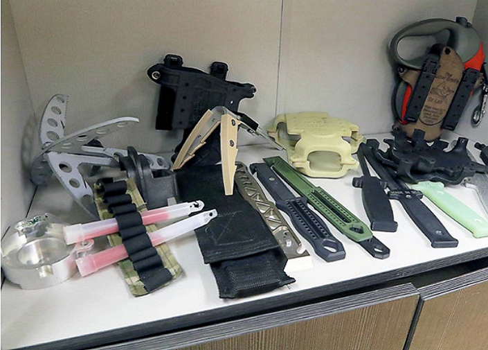
The REF Ex Lab at Bagram Airfield produced these items after Ex Lab engineers worked with Soldiers to develop solutions to problems they encountered.

The US Army has long been putting 3D printing to good use. In an article published in the latest edition of Army AL&T Magazine, senior editor Steve Stark takes a deep dive into just how this branch of the military is using 3D printing, and what barriers stand in its way.

Stark wrote that 3D printing “is a natural fit for the Army” as the military branch works to upgrade its manufacturing technologies. Dr. Philip Perconti, director of the US Army Research Laboratory (ARL), says the technology “is at a pivotal stage in development.”

At the opening of the new Advanced Manufacturing, Materials and Processes (AMMP) manufacturing innovation center in Maryland this fall, Dr. Perconti said, “The Army wants to be at the forefront of this advancement in technology.”

Dr. Perconti believes that mobile production of various replacement parts and components is on the horizon, and he’s not wrong: the Navy, the Air Force, and the Marines are already taking advantage of this application.

3D printing can be used to improve readiness, which is a fairly wide-ranging category that covers everything from buildings and repairs to logistics and sustainment. The overarching goal is to send units out with just the right amount of equipment to establish a mobile unit for on-demand 3D printing.

Mike Nikodinovski, a mechanical engineer and additive expert with the Army’s Tank Automotive Research, Development and Engineering Center (TARDEC), explained that various places around the Army, like its Research, Development and Engineering Command (RDECOM) and the Aviation and Missile Research, Development and Engineering Center (AMRDEC), are currently enhancing readiness, and speeding up the sustainment process, by experimenting with the 3D printing of plastic and metal parts.

“We’ve been repairing parts for the M1 Abrams. … We’ve done projects cross-Army and with the Marine Corps where we printed things like impeller fans. A lot of the things we’ve been doing are just basic one-for-one replacement,” Nikodinovski said. “What can you do with additive for a part that’s traditionally manufactured? A lot of that gets at sustainment, and that’s what we’re trying to stand up at Rock Island—give them the capabilities so they can print metal parts, especially if you want … long-term procurement for parts where you only need a couple, vendors are no longer in business and it doesn’t make a lot of sense to spend a lot of money to set up tooling. Can additive be used to supplement the sustainment process, where I can just, say, print three parts and save all the time it would take to find vendors or set up the tooling?”

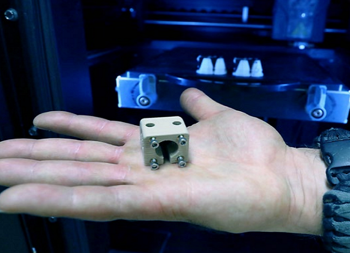
A 3D printed 90° strain relief offset connector, which was designed and fabricated by REF engineers at Bagram Airfield, Afghanistan to prevent cables from breaking when attached to a piece of equipment.

Additive manufacturing is very different from subtractive manufacturing, which means that critical training is involved.

“That’s a huge undertaking. We need to not only train the people who are going to touch and run the machines, but train the troops and the engineers on the capabilities of and how to design for AM,” explained Edward Flinn, the Director of Advanced Manufacturing at Rock Island Arsenal.

“You’ve got to train the Soldier on the capabilities of the technology along with how to actually use the machine. Then there’s how to teach the design community themselves the benefits of additive so they can start designing for it.”

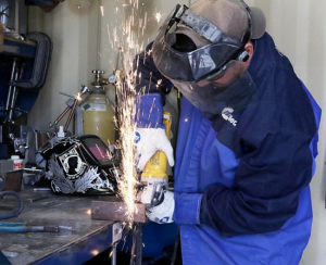
Ryan Muzii, REF support engineer, cuts metal for a project.

Megan Krieger, a mechanical engineer at the Army’s Engineer Research and Development Center (ERDC), explained that the use of makerspaces in the MWRs (morale, welfare, and recreation facilities) at libraries is a helpful way to get military personnel more familiar with 3D printing. She explained that this way, “if people are passionate about making things, they’ll learn it a lot better than if they’re just thrown into it.”

Outside of actually learning how to use the technology, the Army is also working to develop new materials and design tools for 3D printing.

Dr. William Benard, senior campaign scientist in materials development with ARL in Maryland, said, “The Army’s near-term efforts are looking at readiness, and in research, one of the simpler things is to just design new materials that are easier to print with, more reliable to print with, [the] properties are well understood—that kind of thing as a substitute, sort of a more direct approach to support of existing parts.

“One of the areas of investment that ARL is making to support this, and I know others in the RDECOM community are looking at it as well, is, really, new design tools for additive.”

The Army also needs to determine the specific economics of adopting 3D printing. While cost is less of a factor when you’re up against a tight deadline, this reverses when manufacturing reproducibility and cost are more important in a project. Additional factors include how critical the need for the part is, how quickly developments are being made, what else depends on the particular project, and where exactly the Army is spending money.

Tim Phillis, expeditionary additive manufacturing project officer for RDECOM’s Armament Research, Development Engineering Center’s Rapid Fabrication via Additive Manufacturing on the Battlefield (R-FAB), explained, “We as scientists and engineers can talk about material properties and print bed temperatures and print heads and all this kind of stuff, but the senior leadership is looking at, ‘So what? How does this technology improve readiness? How can I keep systems and Soldiers ready to go?’ And that’s what we’re learning.”

Soldiers used R-FAB during a Pacific Pathways exercise in 2017 to print a camera lens cover for a Stryker vehicle in four hours. [US Army photo]

Stark wrote that the Army is mostly “focusing its efforts on its modernization priorities,” and leaving further development up to academia and industry. If our military wants to use 3D printing for real-world applications, this development needs to speed up – these parts must stand up under plenty of stress.

Dr. Aura Gimm, who was managing the Army’s MIT-affiliated research center program at the Institute for Soldier Nanotechnologies at the time of her interview, said, “It’s one thing to create decorative parts, but it’s something else if you’re trying to create a loadbearing or actuating parts that could fail.

“The standardization and making sure that we have metrology or the metrics to test and evaluate these parts is going to be quite critical, for [items made with additive] to be actually deployable in the field. Because one thing that we don’t want is to have these parts … not work as expected.”

Dr. Perconti concurred:

“Ultimately, the goal for us is to enable qualified components that are indistinguishable from those they replace. Remember, when you take a part out of a weapon system and replace it with an additive manufactured part, you’re putting lives on the line if that part is not fully capable. So we have to be very sure that whatever we do, we understand the science, we understand the manufacturing, and we understand that we are delivering qualified parts for our warfighters.”

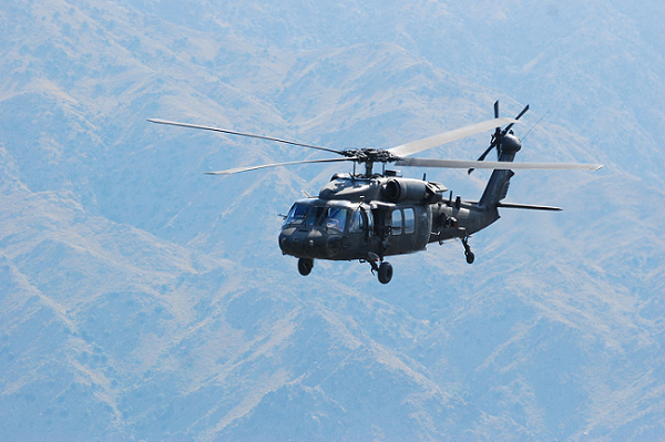
UH-60A/L Black Hawk Helicopter [Image: Military.com]

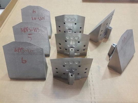
For example, AMRDEC has been working with General Electric Co. to 3D print parts for the T700 motor, which powers both the Apache and Black Hawk helicopters. However, these motor parts are not in use, as they have not yet been tested and and qualified at the Army’s standards. Kathy Olson, additive manufacturing lead in the Manufacturing Science and Technology Division of the Army’s Manufacturing Technology program at Redstone Arsenal, Alabama, said this project is “more of a knowledge transition” to show that it’s possible to 3D print the parts with laser powder bed fusion.

In order to qualify 3D printed parts for Army use, the materials must first be qualified.

“Then you have to qualify your machine and make sure it’s producing repeatable parts, and then qualify the process for the part that you’re building, because you’ll have likely different parameter sets for your different geometries for the different parts [that] you’re going to build,” Olson explained.

“It’s not like you can just press a button and go. There’s a lot of engineering involved on both sides of it. Even the design of your build-layout is going to involve some iteration of getting your layout just such that the part prints correctly.”

One solid application for Army 3D printing is tooling, as changes in this process don’t need any engineering changes.

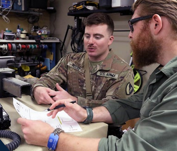
Dr. Patrick Fowler, right, former lead engineer of the Ex Lab in Afghanistan, works with a Soldier on an idea for a materiel solution.

“You can get quick turnaround on tooling,” Flinn explained. “The design process takes place, but the manufacturing can take place in days instead of weeks…For prototyping or for mainstream manufacturing, I can have a tool made [additively] and up and running in 24 hours.”

If applied correctly, 3D printing will allow soldiers deployed all over the world to make almost anything they need in the field.

“What missions can we solve? We’re finding all kinds of things,” said Phillis. “Humvees are being dead-lined because they don’t have gas caps. Or the gas cap breaks. When they order it, they’ve got to sit there for 30 days or 45 days or however long it takes to get that through the supply system.

“If we can produce it in a couple of hours, now we’ve got a truck that’s ready for use while we’re waiting for the supply system to catch up.”

Discuss this and other 3D printing topics at 3DPrintBoard.com or share your thoughts below.

[Images: US Army photos by Jon Micheal Connor, Army Public Affairs, unless otherwise noted]