Evonik Launches FDM PEEK Filament for Implants

PEEK polyether ether ketone is a high-performance thermoplastic with high continuous service temperatures, strength, and low flame smoke and toxicity. Due to this, it is an oft sought material by engineers in applications such as automotive under the hood parts or aerospace parts. But, PEEK is considered to be a wonder material by many not just because it meets a lot of high tech engineering requirements. One can also use PEEK in the body for implants. Several spinal screws, suture anchors, orthopedic implants, and other long term in the body implant products have come to the market recently and in things as diverse as CMF and spine, PEEK is in high demand.

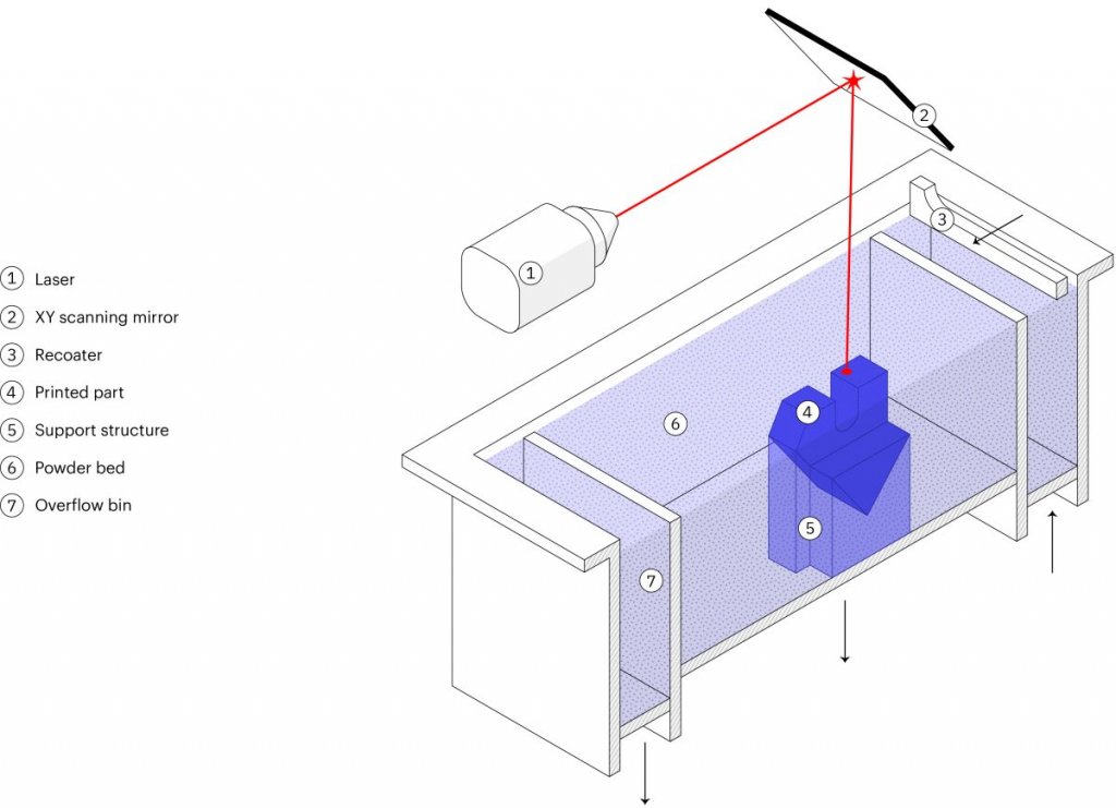
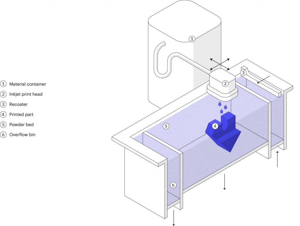
Generally, PEEK implants are made through CNC or if they are printed they are made with SLS (powder bed fusion, sintering). SLS is a tried and true technology that has won approvals for surgical guides and implants. SLS’s high productivity, reliability, and predictability make it a good technology to manufacture things with, especially if they are small and require precision. SLS PEEK powders are expensive however. With SLS a laser, sinters some lose polymer powder on a bed of spread out powder. A new layer is then spread out and the process repeats itself. Unsintered powder acts as a support material and once a big block or cake has been built this is removed from the printer and parts are sieved out and brushed out to remove the loose powder. This remaining powder can then to a certain extent be mixed in with new virgin powder and used again. The recycling rate depends on the powder and the build.

Essentially, if a printer uses a metric tonne of powder a month we end up recycling a third per build and ultimately end up throwing away half a tonne of powder for every 500 Kg’s of built parts. Nota Bene: this is just a general example meant to make people understand the economics of SLS a bit better, with different materials and parts, spot, spacing etc. you’ll get different results. This is still way more efficient than cutting away material for CNC for example, but is quite a waste. If you’re paying $100 a kilo for PA, then this is quite expensive on a monthly basis. And this is for a medium machine working at full production. $50,000 per machine per month, ouch. Imagine you’ve got ten or more.

But, PEEK powder is way way more expensive than that. You’ll be paying five to nine times more per Kilo for PEEK depending on the certification. And it gets worse, because the recycling rate of PEEK powder in SLS machines is effectively 0. We toss out all of it. All of it. Everything that is not a built part is thrown away. So depending on the utilization, specific grade, and machine; you’re tossing out a pair of Ferrari’s per month in powder, per machine. Imagine you’re an entrepreneur with your own service bureau and you walk by some bins every day with 4 911’s worth of powder in them, that you will then toss out that day, that’s got to hurt.

This explains the rationale for Evonik’s launch today of a PEEK Filament for implants. 3D4Makers, 3DXtech, Appium, and other firms have offered PEEK filament for a number of years now. Solvay has a healthcare grade PEEK filament that you can buy as well which is ISO 10993 and suitable for limited contact applications for 24 hours and less. PEEK leader Victrex has sold medical PEEK for implantology to a select few also. Alternative materials such as PEKK from Arkema are available but often not with the certifications and approvals to use long term in the body. Now Evonik has an FDM grade suitable for implants specifically.

Polymer companies are reticent to allow for the use of polymers in the body long term because of the suitability of the material for that purpose and also legal liability. DowCorning a huge joint venture went bankrupt over liability related to breast implants that “never represented more than 1 percent of our business” and yet forced the company to set aside $2.35 billion for claimants. Many polymer firms, therefore, consider possible medical implant polymer revenue not sufficient for a possible headshot for their firm.

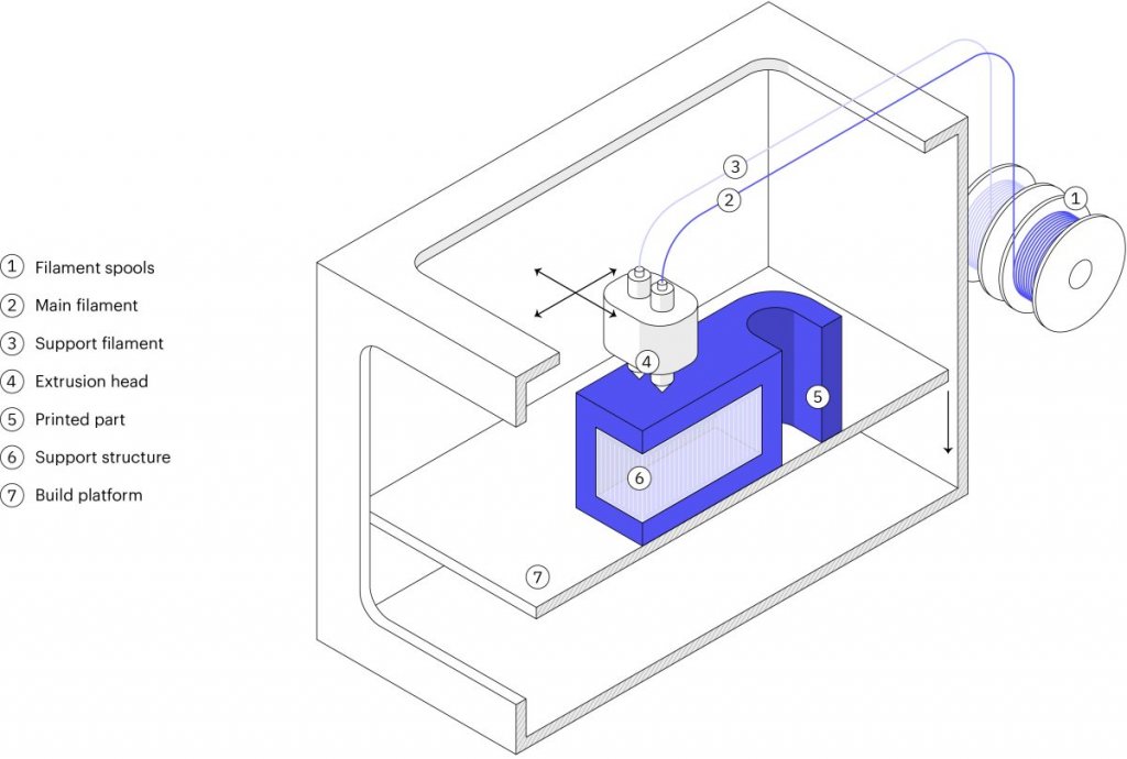
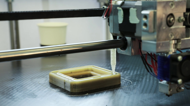
In this case, Evonik has done its homework on its ASTM F2026 compliant PEEK filament. The business case is clear, with FDM you print only the material that you use (plus extra possible support). This means that you will end up using a lot less material per part than if you fill a full SLS machine. Especially with larger implants, FDM does have an advantage in time in the machine and time to part as well. Besides Kumovis and Vshaper, there has been little development of medical part-specific high-temperature printers for FDM. I think that this can be a fantastically profitable niche that would be difficult from which to dislodge a reliable supplier from. Evonik’s launch of this FDM material can serve as an impetus for the development of more medially capable high-temperature FDM printers that one would need in order to use the filament.

With a surgical implant PEEK material the VESTAKEEP i4 3DF, 1.75 mm, on 250 or 500 gram spools is based on VESTAKEEP i4 G with good “biocompatibility, biostability, x-ray transparency, and easy handling.” X-Ray transparency is a great advantage of polymer medical implants since it allows doctors to check if the implant is placed correctly after implantation and lets them do CT scans especially those with contrast die, after or even during implantation or scans which can let them adequately see bone or tissue healing progress. In CT’s and MRI’s metal implants cause artefacts on some scans, or may block surgeons from seeing important details through shadows or opacity. Magnetic implants and MRI’s are also not an awesome combo.

Marc Knebel, of Evonik Medical Devices & Systems,

“For modern medical technology, the development of our first 3D-printable implant material opens up new opportunities for customizing patient treatments. Orthopedics and maxillofacial surgery are examples of areas where this could be applied. Innovative high-performance materials like Evonik’s VESTAKEEP PEEK—along with highly complex hardware and software, and the perfect match between materials and machines—form the basis for a sustainable 3D-printing revolution in medical technology. Therefore, we will successively expand our product portfolio of 3D printable biomaterials.”

In order to make you less gun shy on taking the leap for PEEK Evonik has released a testing grade,

“The term refers to a class of material having the exact same product properties as the implant grade, but without the documentation needed for approval in medical technology applications. This offers a cost-effective way of adapting the processing characteristics of the high-performance plastic to a given 3D printer.”

This is a great idea that other companies should look into adopting as well as it would make research and product development into high-performance polymers much more cost-effective.

The post Evonik Launches FDM PEEK Filament for Implants appeared first on 3DPrint.com | The Voice of 3D Printing / Additive Manufacturing.

US Researchers Create 3D Printing Filament from Recycled Cellulose Polypropylene

In this recently published study, ‘Recycled Cellulose Polypropylene Composite Feedstocks for Material Extrusion Additive Manufacturing,’ researchers from the US explain their findings in using not only composites but those made out of recycled material. Here, the focus is on using polypropylene reinforced with cellulose waste to create 3D printing filament for material extrusion additive manufacturing (MEAM).

With cellulose being more commonly used to strengthen thermoplastics, today, such composites can be helpful in applications such as decking, paneling, furniture, household goods, and more. Not only are they plentiful, but also affordable to use—and best of all, renewable. Such materials also offer strength, low-bulk density—along with less abrasion, meaning that products last longer. To date, many studies have centered around ABS and PLA composites; in fact, some have even included using materials like ground-up macadamia shells with ABS.

For this study, materials like wastepaper, cardboard, and wood flour were used for additives, with powders melted into filament and then printed into samples for testing, considering that mechanical properties could be affected due to filler, along with wettability.

“Strong particle–matrix interfacial adhesion can improve toughness due to efficient stress transfer between phases,” stated the researchers. “On the other hand, poor wetting can lead to debonding, plastic void growth, and shear banding mechanisms, which absorb energy and can improve toughness.”

The composites were created through pulverization, minimizing particles for better results in fabricating samples. The ingredients used for the composite were rather interesting too, in the form of Wegmans and Great Value yogurt containers, along with office printer paper, corrugated cardboard, and wood flour.

“Recycled polypropylene from yogurt containers was cleaned by rinsing with water, ethanol and drying in the air at room temperature. The labels were removed before cutting into pieces that could be fed into the paper shredder (Compucessory model CCS60075). Wastepaper and cardboard were fed through an identical cross-paper shredder,” explained the researchers.

Recycled PP and cellulose starting materials, powder, and filament generated from SSSP. (A) Waste paper, (B) rPP/WP SSSP powder, (C) rPP/WP filament, (D) rPP shreds, (E) rPP/CB SSSP powder, (F) rPP/CB filament, (G) wood flour, (H) rPP/WF SSSP powder, (I) rPP/WF filament. WP = waste paper, CB = cardboard, WF = wood flour.

While all the samples were 3D printed as planned, the researchers pointed out that clogging was an issue for some pieces when using the typical 0.5 mm nozzle. The team theorized that cellulose was responsible for the clogging due to some particles not ground finely enough. Cardboard and paper did not always remain sufficiently mixed either. 3D printing was performed on a Lulzbot Taz 6 3D printer, with a 100 °C bed temperature and a 220 °C nozzle temperature used.

“Sections along the length of a filament spool were examined by scanning electron microscope and thermogravimetric,” concluded the researchers. “The rPP/CB composites have a greater loading of cellulose compared to the commercial PP (cPP)/CB composites, but loading does not change significantly along the ca. 30 ft. examined. Further, weight percent remaining by TGA does not show significant differences in char along each respective filament.”

Ultimate tensile strength (hatched bars) and modulus (solid bars) of printed PP with 10 wt % cellulose. *, **, # significantly different from the respective control. WP = waste paper, CB = cardboard, WF = wood flour.

While 3D printing today offers a host of different materials to choose from as a whole, many are better when reinforced, meaning that composites are becoming increasingly more popular from copper metal to continuous wire polymers or continuous carbon, and more—even to include alternatives like wood and cork.

What do you think of this news? Let us know your thoughts! Join the discussion of this and other 3D printing topics at 3DPrintBoard.com.

Ultimate tensile strength (hatched bars) and modulus (solid bars) of printed PP with 10 wt % cellulose. *, **, # significantly different from the respective control. WP = waste paper, CB = cardboard, WF = wood flour.

[Source / Images: [‘Recycled Cellulose Polypropylene Composite Feedstocks for Material Extrusion Additive Manufacturing’]

The post US Researchers Create 3D Printing Filament from Recycled Cellulose Polypropylene appeared first on 3DPrint.com | The Voice of 3D Printing / Additive Manufacturing.

3D Printing Metal End-use Part Applications

This article describes the ideal use-cases for each process & comparison with other solutions to help you identify opportunities using 3D Hubs in your organization for metal 3d printing service.

Definition: End-use part is any good that is either sold as a product or placed in service within a company’s internal operations.

There are 6 processes to consider:

  1. FDM / FFF (plastics)
  2. SLA / DLP (plastics)
  3. SLS / MJF (plastics)
  4. SLM / DMLS (metals)
  5. Metal FFF (metals)
  6. Binder Jetting (metals)

In part 1 we talked about plastic parts, in part 2 we discuss only metals. 

4. SLM/DMLS

Selective Laser Melting (SLM) and Direct Metal Laser Sintering (DMLS) are metal powder bed fusion 3D Hubs printing processes that are most commonly used today as they are especially suitable for high-end applications since they offer advanced material properties and superb design freedom.

While both utilize high laser power to bond together metal powder particles to form a part– layer-by-layer, SLM will achieve a full melt, while — due to the very high temperatures — DMLS will cause the metal particles to fuse together at a molecular level. 

The majority of metal alloys are compatible with the DMLS method, wherein SLM, only certain (pure) metal materials may be used.

Still, the differences between these two 3D Hubs printing technologies are so slim; they can be treated as the same for designing purposes. 

In this section, we will take a closer look at the technical characteristics, manufacturing process, and the limitations and benefits of these two, very similar techniques.

How it works: SLM/DMLS 3D Hubs printing process basic steps:

  • First, the build chamber is filled with inert gas then heated to the optimum print temperature.
  • A thin layer (typically 50 μm) of metal powder is spread over the build platform.
  • Next, the laser scans the cross-section of the part, selectively bonding the metal particles.
  • Thus, the build platform moves down a layer when the entire area is scanned, and the process repeats until the build is complete.
  • After the printing process is complete, the build must first cool down before the loose powder is extracted.

This step is only the beginning of the SLM/DMLS 3D printing manufacturing process. Once the print is complete, several compulsory and/or optional post-processing steps are also required before the parts will be ready for use. 

Compulsory post-processing steps include

  • Stress relief: Before continuing with any other operation, the internal stresses that develop during printing, due to the very high processing temperatures, need to be relieved through a thermal cycle.
  • Removal of the parts: In SLM/DMLS the parts are welded onto the build platform and EDM wire cutting or a band saw are used.
  • Removal of the support: To mitigate the distortion and warping that occurs during printing, support in SLM/DMLS is required. Support is CNC machined or removed manually.

Additional post-processing steps are often required to meet engineering specifications that may include:

  • CNC machining: When tolerances are tighter than the standard ± 0.1 mm that’s required, machining is employed as a finishing step. Only the slight material is removed this way.
  • Heat treatments: Hot Isostatic Pressing (HIP) or heat treatments can be used to improve the material properties of the part.
  • Smoothing/Polishing: Certain application requires a smoother surface than the standard RA 10 μm of as-printed SLM/DMLS. CNC machining and Vibro, chemical, or manual polishing are available solutions.

How it works: Laser source bonds metal powder particles

Strengths:

  • Geometric freedom
  • High accuracy & fine details
  • High-performance materials

Materials:

  • Stainless Steel
  • Aluminum
  • Titanium
  • Superalloys

Use case #1 – Optimized brackets

DMLS / SLM is used to create lightweight parts through advanced CAD processes, such as topology optimization. They are of particular interest in the automotive and aerospace industries.

Use case #2 – Internal geometries

A far more common use of DMLS / SLM is the creation of parts with internal channels. These find applications in the manufacturing industry (for example injection molding tooling with internal channels for cooling) or for heat exchangers.

Pro tip: Make sure that no support structures are needed to manufacture the internal channels, as they will be impossible to remove.

5. Metal FFF: What is metal extrusion?

Metal Extrusion is a low-cost metal 3D printing process alternative that is most suitable for prototyping purposes or for one-off custom parts.

It is a variation of the classic FDM method for plastics. In 2018, the first Metal Extrusion 3D printers were released also known as an Atomic Diffusion Additive Manufacturing (ADAM) and Bound Metal Deposition (BMD).

A part is built layer-by-layer, like FDM, by extruding material through a nozzle, but the material is not plastic, unlike FDM but is a metal powder held together with a polymer binder. The result of the printing step is a “green” part that needs to be sintered and de-bonded to become fully metal.

Here, we examine the characteristics and key limitations and benefits of this additive process to help you understand how you can use it more effectively.

How does metal extrusion work?

Metal Extrusion consists of a three-stage process involving a printing stage, a de-binding stage, and a sintering stage. 

The Printing Stage…

  • Raw material in a rod or filament form, which basically consists of metal particles that are bound together by wax and/or polymer.
  • This filament or rod is extruded through a heated nozzle and then deposited– layer-by-layer to build a designed part based on the CAD model.
  • While, if necessary, support structures are built. The interface between the part and the support is printed with ceramic support material that can easily be removed later manually.

When printing is complete, the “green” resulting part must be post-processed using similar steps like Binder Jetting, in order to become metal. The “green” part is washed first for several hours in a solution to remove almost all of the binders. Then it is sintered inside a furnace so that the metal particles are bonded together to form the fully-metal part.

During the sintering process, the dimensions of the parts are reduced by about 20 percent. to compensate for this, the parts are printed larger. Like the Binder Jetting process, the shrinkage isn’t homogenous, meaning that trial and error will be required to get accurate results for particular designs.

How it works: Metal/binder is extruded through a nozzle to print the part, which is then thermally sintered.

Strengths:

  • Does not require industrial facilities
  • Based on MIM
  • Complex metal parts

Materials:

  • Stainless steel
  • Tool steel

Main use: For internal operations

An alternative to CNC, Sand casting

Quantity: 1-50 parts

Use case #1 – CNC part replacements

Metal Extrusion is excellent for functional CNC prototyping and small productions of metal parts that would otherwise require a 5-axis CNC machining to produce.

6. Metal Binder Jetting

Metal Binder Jetting is increasing in popularity rapidly. What makes it especially suitable for small to medium production runs, is its unique characteristics.

In this section, we will dive deeper within the steps used in the Binder Jetting to learn the basic characteristics of metal parts production.

What is Metal Binder Jetting?

Metal Binder Jetting is a process of building parts by placing a binding agent on a slightly thin layer of powder in through inkjet nozzles. Originally, it was used to develop full-color models and prototypes from sandstone. A variation of the technique is becoming more popular lately, because of its batch production capabilities.

In metal Binder Jetting printing, the printing step is done at room temperature, which means the thermal effects, such as, internal stresses and warping aren’t a problem, like in SLM/ DMLS, and therefore, supports are not needed. To create a fully metal part, an additional post-processing step is required.

How does Metal Binder Jetting work?

Metal Binder Jetting involves two-stages; a printing stage and a post-processing stage.

The printing process works like this…

  • A thin layer (typically 50 μm) of metal powder is spread out over the build platform.
  • A carriage that has inkjet nozzles will pass over the bed while selectively depositing binding agent droplets of wax and polymer to bond together the metal powder particles.
  • When done, the build platform will move down, then the process will repeat until the entire build is complete.

The result of this printing process is a part of the “green” state. To create fully metal parts and remove the binding agent, a post-processing step is necessary.

This post-processing stage requires two variations: Infiltration and Sintering.

How it works: Binder is jetted onto metal powder particles to create the part, which is then thermally sintered

Strengths:

  • Great design freedom
  • Based on MIM
  • Batch production

Materials:

  • Stainless steel 
  • Tool steel

Main use: Low-run metal production

An alternative to Metal Injection Molding, Die casting

Use case – Low-run production

Binder Jetting is the only metal 3D printing technology today that can be used cost-effectively for low-to-medium batch production of metal parts that are smaller than a tennis ball.

Why engineers use 3D Hubs for 3D printing

Instant quoting & DFM feedback

Build and edit your quote online. Review your parts for manufacturability and assess the cost of different materials, processes and lead times for your project in real-time. Explore our 3d printing service for every type of additive manufacturing project. 

Readily available capacity

Benefit from our network of 250 manufacturing partners to access instantly available capacity. Our manufacturing partners are both local and overseas.

Quality & reliability

Dedicated 3D Hubs team to ensure your parts consistently meet your quality expectations. We also offer phone, email and chat support for any concerns or questions you may have.

The post 3D Printing Metal End-use Part Applications appeared first on 3DPrint.com | The Voice of 3D Printing / Additive Manufacturing.

Makerbot Launches Method X Brings Real ABS 3D Printing to Manufacturing

MakerBot, a global leader in 3D printing, announces the launch of METHOD X, a manufacturing workstation engineered to challenge traditional manufacturing with real ABS (acrylonitrile butadiene styrene) material, a 100°C chamber, and Stratasys SR-30 soluble supports to deliver exceptional dimensional accuracy and precision for complex, durable parts. METHOD X is capable of printing real ABS that can withstand up to 15°C higher temperatures, is up to 26% more rigid, and up to 12% stronger than modified ABS formulations used on desktop 3D printer competitors.1 Real ABS parts printed on METHOD X have no warping or cracking that typically occurs when printing modified ABS on desktop platforms without heated chambers.

Desktop 3D printer manufacturers attempt to get around part deformation that occurs, due to the high shrinkage rate of the material, by using a heated build plate in combination with altered ABS formulations that are easier to print but compromise thermal and mechanical properties. MakerBot Precision ABS has a heat deflection temperature of up to 15°C higher than competitors’ ABS, which are modified to make material printable without a heated chamber. With METHOD X, the 100°C Circulating Heated Chamber significantly reduces part deformation while increasing part durability and surface finish.

The MakerBot METHOD X combines industry expertise and technologies from Stratasys® (Nasdaq: SSYS)—the worldwide leader in industrial 3D printing—with MakerBot’s accessibility and ease of use to provide professionals with an industrial 3D printer at a disruptive price point.

MakerBot ABS for METHOD has excellent thermal and mechanical properties similar to ABS materials used for injection molding applications—making it ideal for a wide range of applications, including end-use parts, manufacturing tools, and functional prototypes. A 100°C Circulating Heated Chamber provides a stable print environment for superior Z-layer bonding—resulting in high-strength parts with superior surface finish. With the MakerBot METHOD X, engineers can design, test, and produce models and custom end-use parts with durable, production-grade ABS for their manufacturing needs.

Also new is the availability of Stratasys SR-30 material for easy and fast support removal. METHOD X is the only 3D printer in its price class that uses SR-30—enabling unlimited design freedom and the ability to print unrestricted geometries, such as large overhangs, cavities, and shelled parts. The combination of SR-30 and MakerBot ABS is designed to provide outstanding surface finish and print precision.

“When we initially launched METHOD, we broke the price-to-performance barrier by delivering a 3D printer that was designed to bridge the technology gap between industrial and desktop 3D printers. This made industrial 3D printing accessible to professionals for the first time. Since then, we have shipped hundreds of printers and received positive feedback from a number of our customers on the precision and reliability of the machine,” said Nadav Goshen, CEO, MakerBot. “With METHOD X, we are taking a step further to revolutionize manufacturing. METHOD X was created for engineers who need true ABS for production-ready parts that are dimensionally-accurate with no geometric restrictions. METHOD X delivers industrial-level 3D printing without compromising on ABS material properties and automation in a new price category.”

Engineered as an automated, tinker-free industrial 3D printing system, METHOD X includes industrial features such as Dry-Sealed Material Bays, Dual Performance Extruders, Soluble Supports, and an Ultra-Rigid Metal Frame. METHOD X’s automation and industrial technologies create a controlled printing environment so professionals can design, test, and iterate faster. The lengthened thermal core in the performance extruders are up to 50% longer than a standard hot end to enable faster extrusion, resulting in up to 2X faster print speeds than desktop 3D printers.2

These key technologies—combined with MakerBot ABS for METHOD—are designed to help engineers achieve dimensionally-accurate, production-grade parts at a significantly lower cost than traditional manufacturing processes. Engineers can print repeatable and consistent parts, such as jigs, fixtures, and end-effectors, with a measurable dimensional accuracy of ± 0.2mm (± 0.007in).3

METHOD X can be used with MakerBot’s lines of Precision and Specialty Materials, including MakerBot PLA, MakerBot TOUGH, MakerBot PETG, MakerBot PVA, MakerBot ABS, and SR-30, with more to come.

MakerBot METHOD X’s automated and advanced features provide users with a seamless workflow to help them optimize their design and production processes. The MakerBot METHOD X is one of the most intelligent 3D printers on the market, with 21 onboard sensors that help users monitor, enhance, and print their projects, including RFID chips, temperature sensing, humidity control, material detection, and more. The METHOD platform provides a seamless CAD to part workflow, with Solidworks, Autodesk Fusion 360 and Inventor plug-ins and support for over 30 types of CAD files, helping users turn their CAD files to parts quicker.

The METHOD platform has been tested by MakerBot for over 300,000 hours of system reliability, subsystem, and print quality testing.4

Shipping of METHOD X is expected to begin at the end of August 2019. To learn more about the MakerBot METHOD X, visit www.makerbot.com/method.

1 Based on internal testing of injection molded specimens of METHOD X ABS compared to ABS from a leading desktop 3D printer competitor. Tensile strength testing was performed according to ASTM D638 and HDT B testing according to ASTM D648.
2 Compared to popular desktop 3D printers when using the same layer height and infill density settings. Speed advantage dependent upon object geometry and material.
3 0.2 mm or ± 0.002 mm per mm of travel (whichever is greater). Based on internal testing of selected geometries.
4 Combined total test hours of METHOD and METHOD X (full system and subsystem testing) expected to be completed around shipping of METHOD X.

About MakerBot
MakerBot, a subsidiary of Stratasys Ltd. (Nasdaq: SSYS), is a global leader in the 3D printing industry. The company helps create the innovators of today and the businesses and learning institutions of the future. Founded in 2009 in Brooklyn, NY, MakerBot strives to redefine the standards for 3D printing for reliability, accessibility, precision, and ease-of-use. Through this dedication, MakerBot has one of the largest install bases in the industry and also runs Thingiverse, the largest 3D printing community in the world.

We believe there’s an innovator in everyone, so we make the 3D printing tools that make your ideas matter. Discover innovation with MakerBot 3D printing.

To learn more about MakerBot, visit makerbot.com.

Note Regarding Forward-Looking Statement

The statements in this press release relating to Stratasys’ and/or MakerBot’s beliefs regarding the benefits consumers will experience from the MakerBot METHOD X and its features and Stratasys’ and MakerBot’s expectations on timing of shipping the MakerBot METHOD X are forward-looking statements reflecting management’s current expectations and beliefs. These forward-looking statements are based on current information that is, by its nature, subject to rapid and even abrupt change. Due to risks and uncertainties associated with Stratasys’ and MakerBot’s businesses, actual results could differ materially from those projected or implied by these forward-looking statements. These risks and uncertainties include, but are not limited to: the risk that consumers will not perceive the benefits of the MakerBot METHOD X and its features to be the same as Stratasys and MakerBot do; the risk that unforeseen technical difficulties will delay the shipping of the MakerBot METHOD X; and other risk factors set forth under the caption “Risk Factors” in Stratasys’ most recent Annual Report on Form 20-F, filed with the Securities and Exchange Commission (SEC) on March 7, 2019. Stratasys (or MakerBot) is under no obligation (and expressly disclaims any obligation) to update or alter its forward-looking statements, whether as a result of new information, future events or otherwise, except as otherwise required by the rules and regulations of the SEC.

The post Makerbot Launches Method X Brings Real ABS 3D Printing to Manufacturing appeared first on 3DPrint.com | The Voice of 3D Printing / Additive Manufacturing.

Collaborative Research Team Develops Density-Graded Structure for Extrusion 3D Printing of Functionally Graded Materials

Microscopic photos of top and side views of printing results with a 0.38 mm wide extrusion path: (a) without versus (b) with overlapping by 0.36 mm respectively. Overlapping extrusion paths exhibit over-extrusion of material at the overlapping region, which results in unwanted blobs on the surface of the print.

Plenty of research has been completed in regards to FDM (extrusion) 3D printing, such as how to improve part quality and how to reliably fabricate functionally graded materials (FGM). The latter is what a collaborative team of researchers from Ultimaker, the Delft University of Technology (TU Delft), and the Chinese University of Hong Kong are focusing on in their new research project.

The team – made up of researchers Tim KuipersJun Wu Charlie, and C.L. Wang – recently published a paper, titled “CrossFill: Foam Structures with Graded Density for Continuous Material Extrusion,” which will be presented at this year’s Symposium for Solid and Physical Modeling.

“In our latest paper we present a type of microstructure which can be printed using continuous extrusion so that we can generate infill structures which follow a user specified density field to be printed reliably by standard desktop FDM printers,” Kuipers, a Software Engineer and Researcher for Ultimaker, wrote in an email.

“This is the first algorithm in the world which is able to generate spatially graded microstructures while adhering to continuous extrusion in order to ensure printing reliability.”

Because 3D printing offers such flexible fabrication, many people want to design structures with spatially graded material properties. But, it’s hard to achieve good print quality when using FDM technology to 3D print FGM, since these sorts of infill structures feature complex geometry. In terms of making foam structures with graded density using FDM, the researchers knew they needed to develop a method to generate “infill structures according to a user-specific density distribution.”

The abstract reads, “In this paper, we propose a new type of density graded structure that is particularly designed for 3D printing systems based on filament extrusion. In order to ensure high-quality fabrication results, extrusion-based 3D printing requires not only that the structures are self-supporting, but also that extrusion toolpaths are continuous and free of self-overlap. The structure proposed in this paper, called CrossFill, complies with these requirements. In particular, CrossFill is a self-supporting foam structure, for which each layer is fabricated by a single, continuous and overlap-free path of material extrusion. Our method for generating CrossFill is based on a space-filling surface that employs spatially varying subdivision levels. Dithering of the subdivision levels is performed to accurately reproduce a prescribed density distribution.”

Their method – a novel type of FDM printable foam structure – offers a way to refine the structure to match a prescribed density distribution, and provides a novel self-supporting, space-filling surface to support spatially graded density, as well as an algorithm that can merge an infill structure’s toolpath with the model’s boundary for continuity. This space-filling infill surface is called CrossFill, as the toolpath resembles crosses.

“Each layer of CrossFill is a space-filling curve that can be continuously extruded along a single overlap-free toolpath,” the researchers wrote. “The space-filling surface consists of surface patches which are embedded in prism-shaped cells, which can be adaptively subdivided to match the user-specified density distribution. The adaptive subdivision level results in graded mechanical properties throughout the foam structure. Our method consists of a step to determine a lower bound for the subdivision levels at each location and a dithering step to refine the local average densities, so that we can generate CrossFill that closely matches the required density distribution. A simple and effective algorithm is developed to merge a space-filling curve of CrossFill of a layer into the closed polygonal areas sliced from the input model. Physical printing tests have been conducted to verify the performance of the CrossFill structures.”

The researchers say that the user prescribes density distribution, and can use CrossFill and its space-filling surfaces, with continuous cross sections, to “reliably reproduce the distribution using extrusion-based printing.” CrossFill surfaces are built by using subdivision rules on prism-shaped cells, each of which contains a surface patch that’s “sliced into a line segment on each layer to be a segment” of the toolpath, which will be made with a constant width; cell size determines the density.

“By adaptively applying the subdivision rules to the prism cells, we create a subdivision structure of cells with a density distribution that closely matches a user-specified input,” the team wrote. “Continuity of the space-filling surface across adjacent cells with different subdivision levels – both horizontally and vertically – is ensured by the subdivision rules and by post-processing of the surface patches in neighboring cells.”

The subdivision system distinguishes an H-prism, which is built by cutting a cube in half vertically along a diagonal of the horizontal faces, and a Q-prism, generated by spitting a cube into quarters along the faces’ diagonals. To learn more about this system and the team’s algorithms, check out the paper in its entirety.

Schematic overview of our method. The top row shows a 2D analogue of our method for clear visualization. The prism-shaped cells in the bottom row are visualized as semi-opaque solids to keep the visualization uncluttered. Red lines in the bottom row highlight the local subdivisions performed in the dithering phase.

The researchers also explained the method’s toolpath generation in their paper, starting with how to slice the infill structure into a continuous 2D polygonal curve for each layer of the object, which is followed by fitting a layer’s curve “into the region of an input 3D model.”

Experiments measuring features like accuracy, computation time, and elastic behavior were completed on an Intel Core i7-7500U CPU @ 2.70 GHz, using test structures 3D printed out of white TPU 95A on Ultimaker 3 systems with the default Cura 4.0 profile of 0.1 mm layer thickness. The team also discussed various applications for CrossFill, such as imaging phantoms for the medical field or cushions and packaging.

“The study of experimental tests shows that CrossFill acts very much like a foam although future work needs to be conducted to further explore the mapping between density and other material properties,” the researchers concluded. “Another line of research is to further enhance the dithering technique, e.g. changing the weighing scheme of error diffusion.”

CrossFill applications. (a) Bicycle saddle with a density specification. A weight of 33 N is added on various locations to show the different response of different density infill. (b) Teddy bear with a density specification. (c) Shoe sole with densities based on a pressure map of a foot. (d) Stanford bunny painted with a density specification. (e) Medical phantom with an example density distribution for calibrating an MRI scanning procedure.

The team’s open source implementation is available here on GitHub. To learn more, check out their video below:

Discuss this story, and other 3D printing topics, at 3DPrintBoard.com or share your thoughts below.

Rapid 2019: Interview with John Dulchinos VP 3D Printing and Digital Manufacturing at Jabil

Jabil is a huge contract manufacturing firm that makes and develops products for the brands that you know. With over 100 factories and $22 billion in revenue and over a 200,000 employees Jabil’s interest in 3D printing can have huge ramifications for our industry. Just this one firm could broadly adopt our technology and drive adoption forward. With end-user products having to be made at high volume and low-cost Jabil is not the first firm you may think of when you look at 3D printing. After all, in highly customized industries and high-end applications such as satellites the 3D printing business case is more easily made. Jabil has been doing some fundamentally very interesting things, however. The firm has developed and is making materials which will lower its own costs, it went into the production of footwear and insoles, and set up a 3D printing network while deploying Ultimaker 3D printers and betting big on HP.

Jabil seems to be making a steadfast move in engaging the 3D printing market in a fundamental way. Moreover especially with a global network of manufacturing, a lot of volume, the expertise in making 3D printers itself and its own materials the firm may yet cement significant advantages into the fundamental economics of manufacturing and prototyping. With contract manufacturing being cutthroat and low margin anything that can give them an advantage may have significant knock-on effects. If it makes sense for an automotive manufacturer to adopt 3D printing then it will doubly so make sense for contractors in tight spots on tight deadlines to do so. This is especially true if they can accelerate prototyping, tooling or customization through 3D printing; offer more customized products at lower costs or bridge manufacture more efficiently. Any incremental move towards the ability to do mass customization at scale or to engage in profitable high mix low volume manufacturing could spell doom for competitors.

Heading up Jabil’s considerable 3D printing engagements and investments is VP John Dulchinos. 3DPrint.com spoke with him at RAPID to find out more.

HP printers at Jabil in Singapore

What is Jabil’s strategy in 3D printing?

Our mission is to accelerate the adoption of Additive Manufacturing. We are focused on how do we take an immature solution set and turn it into a manufacturing technology. We want to produce parts in a certified environment. We want to be able to stand behind the parts that we are making.

At the core, we want to make parts. That’s the foundation. This means that we need to engineer materials because there isn’t a good solution set in materials out there for us to use. In 3D printing, you can get any material as long as it is white PA 12 (polyamide). Usually, specific materials are available for specific solutions and in AM this has not been the case. This limitation meant that we had to develop and sell our own materials

What are you doing in AM? 

If we look at our clients, they are world-class companies. We work for companies such as HP and Cisco. Top brand companies. At a baseline level, we want to do programs with those companies. In order for us to do that we have to engineer the entire workflow. From the translation in the software to the design file, all of it.

We are interested in aerospace, automative, transportion in general, medical devices, orthopediccs and consumer goods.

Is this contract manufacturing of something else? 

Especially for consumer-facing products in things like mass customization application you really need the whole stack to make it make sense. We can do ideation and we can take something from an idea to a solution set.

For us, it is important to understand how and if additive creates value for customers. The more value that there is for them the more possible value there is for us as well.

What are some interesting applications? 

I’m an engineer. So I think of it in terms of a logic tree. For a lot of things, 3D printing doesn’t actually make sense. From a cost standpoint it does not map out well when compared to traditional manufacturing. In some low volume applications it makes sense especially in things such as aerospace and spare parts. In aerospace you can, for example, combine parts, save weight. This creates significant value. Late in life parts are also very expensive to keep and produce, here additive also is very usefull.  There are many great applications in healthcare as well.  Personalized medicine, but broader still also personalized products have much value. In performance, automotive people also want to pay for optimal parts. We can pay for outcomes in additive but that won’t work for all functional production parts. 

With Renault F1 now. we are their on demand production partner. We can now supply parts for on the F1 car. We love this since F1 is like we are very engineering driven. This partnership aligns well with us. It fits Jabil’s manufacturing pedigree. 

Are you expanding your materials and printers portfolio? 

We’ve made a number of materials and want to release a material a month soon. As for printers we operate close to 300 at the moment.

Is 3D printing helping Jabil? 

On the design side, for sure 3D printing is speeding up our business. With designs we can now make more iterations. With fixtures and tooling, we are also much faster. We have well documented case studies where we have gone from making a fixture in 4 to 5 weeks in five days. We can also do more quicker iterations in the fixture.

As an anecdotal piece of evidence, we had one fixture used to electrically test a part. It had a slot at the botton through which the operator had to put their hand. Every once in a while the operator’s fingers would slip and touch the circuit board, shorting it. Once this was discovered it took 3 hours to design and two hours to print a solution for this problem. Within five hours we had, thanks to 3D printing, addressed the quality issue. 

We also have some really good design for additive examples on recent client projects. In one example we took an existing assembly of 39 parts and reduced it to two. Reduction in assembly processes also happened as a result of this. We used 3D printing to simplify the part and the production process. 

Desktop Metal Raises $438 Million Total With Additional $160 Million Round What Does It Mean?

Desktop Metal is becoming quite the VC darling. The Massachusets based metal printing firm has now raised a total of $438 million by virtue of its latest funding round of $160 million. This round led by Koch Industries’ Disruptive Technologies investor gives the company a valuation of over $1.5 billion.


Desktop Metal CEO Rik Fulop said that,

“We are at a critical juncture in the advancement of metal 3D printing and additive manufacturing. We are excited about Koch being an investor, customer and capability provider in this round. This new funding will fuel the continued development of our metal 3D printing technology and rich product roadmap, the scaling of operations to meet a growing demand of orders, and the financing of major new research and development initiatives. Combined, this will set us on a trajectory to become a global leader in metal 3D printing, a key pillar of Industry 4.0.”

While Chase Koch of Koch Disruptive Technologies stated that,

Desktop Metal’s 3D printing solutions can redefine prototyping and mass production of metal products, which has profound disruptive implications for manufacturers like Koch Industries.” “We are very bullish about the prospects of Desktop Metal, not just as an investor, but also as a customer and partner.”

What is significant about this? 

KDT’s investment is notable in size but also notable in that other firms such as Ford and GE have invested in the firm as well. Especially in 3D printing, we are starting to see an outsized impact from manufacturing/industrial companies and their venturing arms. Companies such as Stanley Black and Decker are even collaborating on funding series of firms. That 3D printing will be a disruptive force in industry is well understood by us inside the industry but is becoming more commonplace outside of it also.

Many believed that the mighty Desktop Metal engine was running on fumes so this investment is timely, to say the least. It propels Desktop Metal to new heights. If they can unlock all of this capital then they can easily outspend much larger established 3D printing companies in R&D for example.

HP is a behemoth and one could easily assume that they would have the reach and resources to be outspending everyone in the metal printing race. This investment clouds this for the near term and could give Desktop Metal edge.

This kind of investment should also mean that MarkForged could seek more capital if it wants to engage in an arms race with Desktop Metal.

Will companies such as Xjet and Exone also increasingly target more desktop machines in order to not have a kind of Innovator’s Dilemma problem and be surpassed from below?

Rik Fulop’s mastery in obtaining cash could give the company a huge war chest to see of new competition in inkjet while keeping established firms at bay.

What does this not change? 

Binder jetting metal or FDM combined with wax/polymer metal is not a race that is run. It is also not a filter for my phone pictures or a social network. We’re talking about very difficult hardware, materials and software challenges that have yet to be solved.

Acceptance is key in 3D printing and people are buying machines to help them in an organized way manufacture. Hype will fan the flames but peter out if the performance is not there.

So in adoption, there will be challenges in scaling the Desktop Metal service offering and the quality, output, and yield of machines over time. A lot of capital will have to be deployed there or partners will have to pick up the slack in service at least.

The MIM industry has been trying to solve shrinkage rates on injection molded metal parts for decades. They have not been able to do so successfully. In testing parts I’ve always remained skeptical of binder jetting metals or in wax/polymer FDM for metals. I predict that shrinkage differences in part size, across wall thicknesses and geometries, will continue to be problematic for users.

Distortion on parts, stringing, misprints in the FDM step are also potential issues with the Desktop Metal process.

This well-capitalized company with a lot of candle power is also up against Xjet which has a wealth of inkjet knowledge and one of the global homes of Inkjet prowess HP. Meanwhile, Markforged continues to grow hard making this binder jetting metals space a very competitive one.

There are however other inkjet patent heavy firms that may see this investment as an enticement to also make a similar system. It also may deter them.

GE will join this space, but who else will as well?

As well as companies that are working with similar technologies we have Digital Alloys and other new entrants that are also playing in this space.

People often forget that DLP and SLA machines make tens of millions of metal cast parts as well per year. Could increased automation make these systems competitive for many types of shapes as well?

Will Fused Deposition Modeling companies look more towards looking to metalized filaments for creating similar parts than Desktop Metal can make?

We will need to verify part densities, repeatability and how these parts function in the real world to really know how productive either Studio or larger production units can be for firms.

Will many companies continue to bet on HP because they have an established name? Or will Desktop Metal be able to parlay this move into inertia and inevitability?

The company has repeatedly missed launch deadlines and implementation dates with customers.

Experience with part production by others is very limited with Desktop Metal systems. There are few verifiable metal printed parts available at client sites and there is little data on the real world performance of Desktop Metal systems.

Outlook 

Investors seem to believe that the inexpensive metal printing opportunity is huge and that it may be winner takes all. Is it though? It is far too early to tell but I would assume that many tens of thousands of factories and design firms worldwide would profit from having on-site tooling and parts in metals. In prototyping, bridge manufacturing, tooling, and unique parts this could mean that we have thousands of machines as an opportunity. How many of those firms want the staff to do the debinding and sintering in house? If we add the labor cost, and the trouble will we really all have machines on site? Companies now don’t do their own HR and IT but Bob is going to get a room to print parts in on site?

This in my mind is a real unknown and would really depend on what the local metal printing service offering is and what parts people need when. How many have the right volume in parts to warrant this specific system? Yes, pizzas are the future but where and when will I opt for Dominos and when to make my own pizza? I’m confident that inexpensive metal parts for industry is a huge potential segment but what will be the form factor and throughput of machines in this area?

All in all I think that the hype in this particular area is over-optimistic money wanting desperately to plant a flag somewhere. There is an opportunity but this opportunity is not as self-fulfilling as it is in online video or social networks. There are fundamental complexities with binder jetting metals/extrusion with polymer metal filaments that will continue to be challenging. Desktop Metal has not demonstrated that they meet these challenges in real-world production. At the same time, many FDM firms could attempt something much less expensive that does work for a certain set of customers. I’m not convinced that Desktop Metal has the crown planted firmly on its own head at the moment. If the team continues to outperform and executes well in the year to come however then they could turn themselves into the company in pole position in metals.


Scroll and Diaphragm Nozzles with Gear Pumps: A Better Way to 3D Print?

FDM 3D printing. [Image: Fraunhofer IPA]

Fused deposition modeling (FDM) 3D printing, also referred to as material extrusion, is a technique that deposits heated material through a nozzle in order to fabricate parts and components. Rollers in the extruder generate enough pressure to squeeze material into a liquefier, before it melts into a semi-liquid or liquid form and is pushed out the nozzle to solidify and form filament upon contact with either the build platform or a previously extruded layer.

You may not realize it, but the type of 3D printing nozzle you use does actually make a considerable difference in the quality of your 3D print. A group of researchers from the Department of Mechanical and Aerospace Engineering at the University of Florida recently published a paper detailing two types of nozzle that may be better for the FDM 3D printing process.

In the paper, titled “A fundamental study of parameter adjustable additive manufacturing process based on FDM process” and published in the open access MATEC Web of Conferences publication series, the researchers explain that traditionally, it’s believed that an important part of a 3D printed part’s resolution is contributed by a small cross-sectional area of each material extrusion stand. But, smaller cross-sectional filaments have slower rates of extrusion, which increases build time.

There have many attempts to fix this issue, such as applying each layer’s maximal permissive thickness or using lower support volume to target a shell-like structure. But, the researchers note that there hasn’t been a lot of adjustment to the extrusion parameters to control resolution during the FDM process.

The abstract reads, “In Fused deposition modeling (FDM) process, there has been a confliction between high productivity and high quality of products. The product resolution is proportional to the flow rate of heated material extrusion, which directly affects the build time. To reduce the build time with acceptable resolution, the idea of parameter adjustable printing process has been introduced. The controllable extruder was modified and two types of diameter changeable nozzle have been designed. This work realizes different resolution building based on the part geometry during FDM process, which can efficiently assure the quality of products and improve the productivity at the same time.”

The diameter of an FDM 3D printer’s nozzle can not only affect the material extrusion rate, but also the resolution of a 3D print. Once the resolution has been determined, its corresponding extrusion parameters can be successfully calculated to determine the relationship between the parameters and the part’s geometry.

“In this paper, the nozzle diameter was chosen as the main changeable extrusion parameter,” the researchers explain. “The extruder of the printer was modified to fit the new process, which determined the extrusion parameters under the certain resolution. The relationship between the part geometry and needed resolution was derived and two kinds of diameter changeable nozzle were designed for the process.”

Viscous fluid flows are typically metered with positive displacement gear pumps, so the researchers used one in the 3D printer’s extruder for their study.

“The speed of the nozzle movement is assumed to be the same as the material extrusion speed for a reliable resolution,” the researchers said.


An optical component called an iris diaphragm has several thin, smooth blades arranged in such a way as to form a round aperture. Due to its controllable aperture diameter, this diaphragm is often used to limit how much light is transmitted to an imaging sensor in camera shutters. That made it a good choice for a component that can change a 3D printer nozzle’s diamater.

“Compared to the traditional extrusion printing nozzle, the iris-shaped nozzle can adjust the diameter easily and realize the changeable diameter during the printing process,” the researchers explained in the paper. “The multi-blades of iris diaphragm can guarantee the circular cross-sectional shape of the nozzle. It is feasible to change the diameter of the nozzle precisely and rapidly by utilizing electronic control system.”

Geometry of scroll nozzle.

But, even if an iris shape could change a nozzle’s diameter, it may also have some gaps around the round aperture, cause leaks during material extrusion, and the high temperature could even soften the blades and lead to damaged prints. That’s why the researchers conceived of a scroll model that would work “without setting the extra planes in the nozzle.”

Inspired by paper scrolls, the circular bottom of the scroll nozzle will become smaller as the shape is rolled, though it will continue to be round. That’s why a scroll model, with its easy diameter control, may be a better choice for a 3D printer nozzle with a changeable diameter than the iris diaphragm shape.

The researchers concluded, “So far, the theoretical model for the parameter adjustable FDM process has been built up. The extruder of the printer was modified using positive displacement gear pump for controlling the flow rate by changing rotation rate so that the resolution, which is represented by filament diameter, could be adjusted by the flow rate during the extrusion process under certain optimal extrusion speed. The desired filament diameter of each building layer was determined by the part geometry using either external-slope criterion or small-feature criterion.”

A few issues to be cleared up during future studies include mechanical performances and resolution of a part’s internal sections and challenges in material selection.

Co-authors of the paper are Qia Wan, Youjian Xu, and Can Lu.

Discuss this story and other 3D printing topics at 3DPrintBoard.com or share your thoughts below.