Using Robotic GMAW Additive Manufacturing to Make Metal Components for Industrial Applications

Gas metal arc welding (GMAW) additive manufacturing is a more affordable metal technology, with a high deposition rate for potentially fabricating medium and large components. Van Thao Le, with Le Quy Don Technical University in Vietnam, has published a paper, titled “A preliminary study on gas metal arc welding-based additive manufacturing of metal parts,” that centers around investigating the mechanical properties and internal quality of components 3D printed using a GMAW robot.

GMAW-based technology is better for manufacturing metal parts with large dimensions than gas tungsten arc welding (GTAW) and plasma arc welding (PAW) methods because of its higher deposition rate. It’s important to achieve high internal quality of GMAW-printed parts, which is why it’s necessary to gain a better understanding of their microstructures – particularly when the component will be used in a load-bearing condition. This technology is consistently used in Vietnam because of its lower cost, so manufacturers should know all they can about the method in order to attain good results.

“Therefore, the objective of this study is to investigate the internal quality of thin-walled parts manufactured by the GMAW-based AM process. The results obtained in this study allow us to demonstrate the feasibility of using the GMAW robot for manufacturing or repairing/remanufacturing of metal components according to the AM principle,” the author wrote.

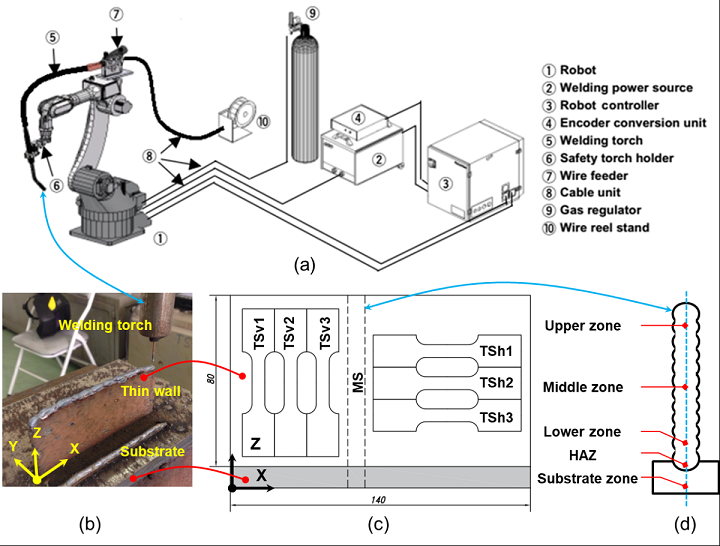
Figure 1. (a) Schema of the GMAW-based AM system, (b) built thin-walled sample, (c) positions for cutting the specimens, & (d) five zones for observing microstructures and measuring the hardness on a cut surface of the specimen.

An industrial GMAW robot built a thin-walled component using the wire arc additive manufacturing (WAAM) process, out of mild steel copper-coated welding wire on a low-carbon steel substrate plate. The 6-axis robot used a welding torch to deposit layers from the substrate, and you can see the welding process parameters in the table below.

“The distance between the GMAW torch and the workpiece was 12 mm. The deposition was conducted at room temperature and without preheating the substrate,” Le explained. “Once the deposition of a welding layer was finished, the welding torch is retracted to the beginning point for the deposition of the next layer with a dwell time of 60 seconds. The dwell time used between two successive layers aims at cooling down the workpiece and transferring accumulated heat to the environment.”

A wire-cut electrical discharge machining (EDM) machine was used to cut two groups of tensile specimens from the thin-walled sample, so that the author could measure the built material’s hardness, using a digital microhardness tester, get a closer look at its microstructures with an optical microscope, and test the tensile properties.

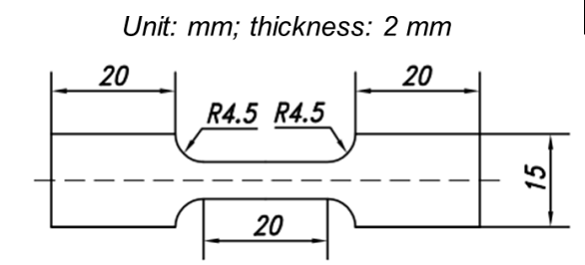
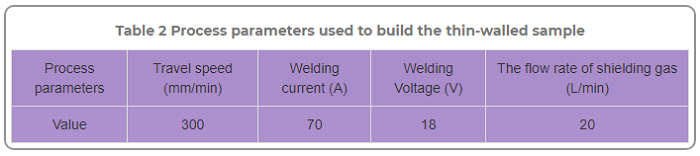
Figure 2 . Dimensions of the tensile specimen.

“Before cutting these specimens, two side surfaces of the built thin wall were machined to obtain an effective width of the built thin-walled materials,” Le wrote.

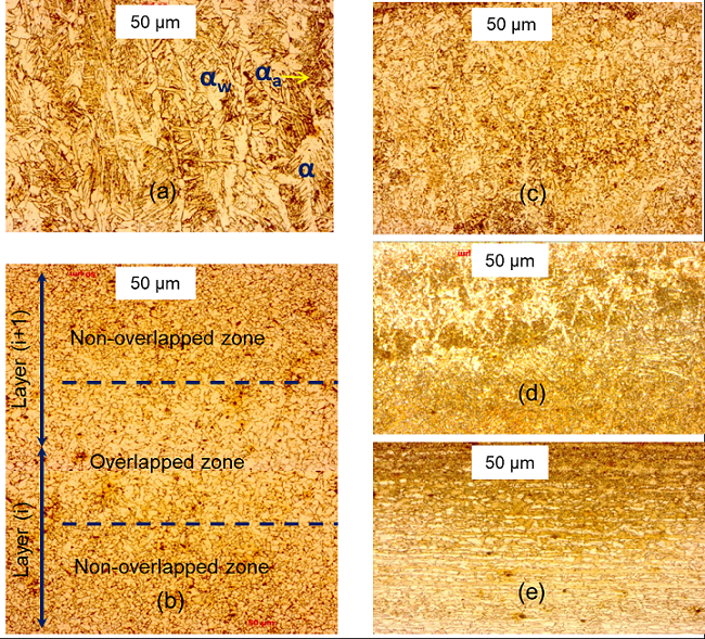
Figure 3. Microstructures of built materials observed in five zones: (a) upper zone, (b) middle zone, (c) lower zone, (d) heat-affected zone (HAZ), and (e) substrate zone.

The specimen’s microstructure was observed in five different zones. The upper zone, which features three types of ferrite grains and a high variation of thermal and high-cooling rates, has “lamellar structures with primary austenite dendrites” that distribute perpendicular to the substrate. The middle zone has two types of grains, and mostly features “the granular structure of ferrites with small regions of pearlites at grain boundaries.” The microstructures found in the lower zone, which has a slower cooling rate than the upper, are made of “equiaxed grains of ferrite, in which thin lamellae are distributed and coexisting with thin strips of pearlite.” These grains are finer than the ones in the middle zone, because the value of thermal shock is higher here.

In the heat-affected zone (HAZ), the microstructures transfrom from austenite to martensite, while the substrate zone features ferrite/perlite banded microstructures – the total opposite of the middle zone’s “homogenous distribution of phases.”

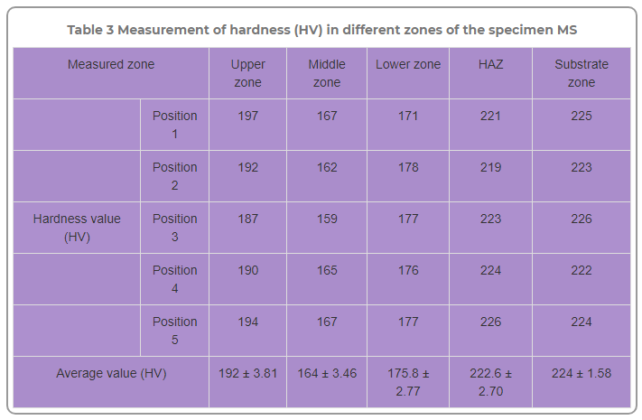
The above table shows the hardness (HV) measurement in the five zones. The upper zone had the highest HV, while the middle had the lowest, and the HAZ’s value was slightly lower than the substrate zone.

Specimens were tested on a tensile machine, and Le also figured the engineering strain-stress curves.

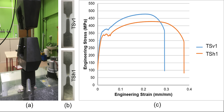
Figure 4 . Tensile tests with two specimens TSv1 and TSh1: (a) Installation of the specimen on the tensile test machine, (b) the broken specimens after the tensile tests, and (d) the engineering stress-strain curves.

“The hardness (ranged between 164±3.46 HV to 192±3.81 HV), yield strength (YS offset of 0.2% ranged from 340±2 to 349.67±1.53 ), and ultimate tensile strength (UTS ranged from 429±1 to 477±2 ) of the GMAW-based AM-built components were comparable to those of wrought mild steel,” he explained.

“There is also a significant difference in terms of YS and UTS between the vertical and horizontal specimens due to non-uniform microstructures of built materials. Moreover, the mechanical properties of the thin-walled component built by the GMAW-based AM process are comparable with those of parts manufactured by traditional processes such as forging and machining.”

This study found that the metal components built by GMAW-based robotic AM have “adequate and good mechanical properties for real applications.” Le concluded that it is feasible to use a GMAW robot to 3D print parts that can be used in industrial applications.

Discuss this research and other 3D printing topics at 3DPrintBoard.com or share your thoughts in the Facebook comments below.

The post Using Robotic GMAW Additive Manufacturing to Make Metal Components for Industrial Applications appeared first on 3DPrint.com | The Voice of 3D Printing / Additive Manufacturing.

Researchers Compare Microstructure of As-Cast, Hot-Extruded, and 3D Printed Magnesium Alloy Samples

Fig. 1: SEM micrographs of the WE43 alloy powder

Alloys of the shiny gray chemical element magnesium (Mg) feature a high strength-to-weight ratio and a low density of about 1700 kg/m3, making them good options for technical applications in the automotive, aviation, and medical fields. But it’s been determined that their weight can be further decreased if porous structures are formed – which can be achieved with 3D printing. A team of researchers from the University of Chemistry and Technology Prague and the Brno University of Technology, both in the Czech Republic, wanted to study the microstructure of a particular magnesium alloy after it had been fabricated using three different methods: as-cast, hot-extruded, and 3D printed with SLM technology.

SLM 3D printing can achieve complex geometric shapes, but there are issues when it comes to fabricating magnesium alloys with this process, mainly high reactivity of magnesium powder, which can lead to unsafe oxide particles forming within 3D printed parts. Patrícia Krištofová, Jiří Kubásek, Dalibor Vojtěch, David Paloušek, and Jan Suchý recently published a study, titled ” Microstructure of the Mg-4Y-3RE-Zr (WE43) Magnesium Alloy Produced by 3D Printing,” about their work mapping an SLM 3D printed magnesium alloy’s microstructure.

“Magnesium alloys made in the form of 3D printing are relatively new production processes,” the researchers wrote. “The study therefore this process compared with current processes, which are now well known and mapped. It was therefore studied the microstructure produced by three different processes of production. The microstructure and chemical composition of present phases were studied using scanning electron microscopy (SEM) and energy dispersive xray spectrometry (EDS). Based on the microstructural examination, significant differences were found between the materials produced by different production processes. The microstructure of the as-cast alloy consisted of relatively coarse α-Mg dendrites surrounded by eutectics containing intermetallic phases rich-in alloying elements. During hot extrusion, the eutectics fragmented into fine particles which arranged into rows parallel to the extrusion direction. The 3D printed alloy was characterized by significantly refined microstructure due to a high cooling rate during the SLM process. It consisted of very fine dendrites of α-Mg and interdendritic network enriched-in the alloying elements. In addition, there were also oxides covering original powder particles and the material showed also some porosity that is a common feature of 3D printed alloys.”

The team used an SLM Solutions 280HL 3D printer to fabricate 15 × 5 × 60 mm rectangular samples of WE43 magnesium alloy, and used SEM and EDS to study their microstructures; then, these were compared to identical materials that had been manufactured through simple gravity casting and hot extrusion.

“The first sample was an as-cast ingot of 60×80×500 mm in size purchased from an industrial supplier. The second WE43 alloy sample was prepared by hot extrusion of the ingot. Cylinders with a diameter of 30 mm and a length of 60 mm were directly cut from the ingot and then extruded at 400°C, extrusion rate of 2 mm/s and extrusion ratio of 16. The resulting extruded rods had a diameter of 7.5 mm,” the researchers explained.

“The analysis revealed that 10% of the WE43 alloy powder particles had a size of 26.9 μm, 50% to 39.8 μm and 90% to 57.9 μm. Thus, the powder contains a sufficient amount of both larger and smaller particles. With respect to the particle size, the size of the building layer was 50 μm.”

The team conducted microscopic observations of the samples, and you can see the views of their microstructures in Figure 2.

Fig. 2: SEM micrographs of the WE43 alloy: a) as-cast, b) hot extruded, c) 3D printed by SLM, d) 3D printed by SLM – detail.

The as-cast alloy has a coarse microstructure, while the microstructure of the sample fabricated with hot extrusion was “considerably” modified. The microstructure of the 3D printed sample is completely different from the other two, featuring regions about 20-50 µm in size that are surrounded by thin boundaries.

“In addition, residual porosity is observed as dark areas between grey regions. The shape and size of grey regions indicates that these regions correspond to original powder particles, either totally or partly melted by laser beam,” the researchers explained. “A more detailed image in Fig. 2d shows very fine internal microstructure of these particles. It contains α-Mg dendrites (dark) surrounded by interdendritic regions (light) enriched in Y and RE elements. The average thiskness of dendritic branches is only approx. 3 µm, suggesting very high cooling rates during the SLM process. In literature focused on the SLM process, cooling rates of 103-106 K/s are often reported.”

The researchers also studied the distribution of elements in the material’s structure, which showed that both the hot-extruded and as-cast material samples had very low oxygen concentration. But the SLM 3D printed sample showed a different story, illustrated in Figure 5 and Table 4.

Fig. 5 Microstructure of the SLM WE43 alloy (SEM) and elements distribution maps (EDS).

“First, element maps and point analysis demonstrate an increased concentration of oxygen in the material which is located mainly in pores (point 1) and also at bondaries between melted powder particles. In the particle interior the O-concentration is very low (point 2),” the researchers wrote. “Second, element map in Fig. 5 also indicates increased content of Y at powder particle boundaries. It can be assumed, that partial oxidation of the powder occurred during the SLM process inside the building chamber. Most probably, the atmosphere contained traces of residual oxygen which reacted preferentially with yttrium due to a high chemical affinity of these elements. For this reason, imperfect connection between powder particles and porosity are observed.”

Results show that an SLM material’s microstructure is “extremely fine” because of high cooling rates, and will also feature a high oxygen concentration “due to a high affinity of the alloy to this gas.” This creates an “imperfect connection” between powder particles and porosity. The researchers plan further studies of this magnesium alloy in order to produce pore-free compact material and decrease the “harmful influence of residual oxygen.”

Discuss this research and other 3D printing topics at 3DPrintBoard.com or share your thoughts below.

The post Researchers Compare Microstructure of As-Cast, Hot-Extruded, and 3D Printed Magnesium Alloy Samples appeared first on 3DPrint.com | The Voice of 3D Printing / Additive Manufacturing.

TU Delft Researchers Discuss Microstructural Optimization for 3D Printing Trabecular Bone

Trabecular bone, also known as spongy or cancellous bone, is one of two types of bone found in the human body. It is found at the end of long bones, in the pelvic bones, ribs, skull and vertebrae. Trabecular bone is one of many microstructures with spatially varying properties found in nature. In a paper entitled “Compatibility in microstructural optimization for additive manufacturing,” a group of researchers points out that these microstructures can now be created by additive manufacturing. One challenge in the computational design of such materials is ensuring compatibility between adjacent microstructures. The researchers’ work aims to find the optimal connectivity between topology optimized microstructures.

“Given the fact that the optimality of connectivity can be evaluated by the resulting physical properties of the assemblies, we propose to consider the assembly of adjacent cells together with the optimization of individual cells,” the researchers explain. “In particular, our method simultaneously optimizes the physical properties of the individual cells as well as those of neighbouring pairs, to ensure material connectivity and smoothly varying physical properties. This idea is substantiated on the design of graded microstructures with maximized bulk moduli under varying volume fractions. The graded microstructures are employed in designing an implant, which is fabricated by additive manufacturing.”


When designing orthopedic implants, the researchers point out, it “may be desirable to have a continuous transition from denser microstructures in the central region to highly porous microstructures at the bone-implant interface.” This functional gradation promotes bony ingrowth at the bone-implant interface, they continue, while maintaining structural integrity and increasing mechanical properties in areas where bony ingrowth is not relevant.

The researchers presented a method of ensuring mechanical compatibility among topology optimized microstructures.

“Our results show that the bulk moduli of individual cells reach the theoretical bounds predicted by the Hashin–Shtrikman model, meaning that the optimization of compatibility does not compromise the performance of individual cells,” they state. “Furthermore, the bulk moduli of neighbouring pairs also agree well with the Hashin–Shtrikman bounds.”

The method was extended to allow maximum length scale and isotropy in microstructures. The researchers demonstrated the effectiveness of their proposed method in a number of designs, including functionally graded materials and multiscale structures. They also showed that the optimized microstructures can be fabricated by additive manufacturing technology. This has implications for a number of applications, including orthopedic implants, which 3D printing can optimize for better growth of new bone.

“As future work, we are particularly interested in the following aspects,” the researchers conclude. “Firstly, this method is directly applicable to 3D design problems. To alleviate the computational burden in 3D, the GPU-based topology optimization framework can be used. Secondly, while we have applied the compound formulation for maximizing bulk modulus, its applicability to other physical problems such as conductivity is left to be demonstrated.”

Authors of the paper include Eric Garner, Helena M.A. Kulken, Charlie C.L. Wang, Amir A. Zadpoor and Jun Wu.

Discuss this and other 3D printing topics at 3DPrintBoard.com or share your thoughts below. 


Researchers Study the Microstructure of Laser Cladding

Distribution of crystallites in the cross-section of deposited droplets with different contact angle 10° (a) and 30° (b).

While metal additive manufacturing has plenty of benefits, it has its drawbacks as well. Two of those drawbacks are high production costs and often unpredictable failure of parts. Laser cladding (LC) is one commonly used method of metal 3D printing, but has an additional limitation that includes a narrow processing window. This is discussed in a paper entitled “On the role of capillary and thermo capillary phenomena on microstructure at laser cladding.”

“Direct numerical simulation (DNS) of heat-mass transfer during LC has proved to be a cost-effective method of searching for the optimal processing parameters which allows making a glance into this technology,” the researchers state. “Application of the DNS to test the troublesome regions that could be identified at the process planning stage can boost the quality and flexibility of direct fabrication.”

The researchers’ aim was to develop a coupled kinetic-hydrodynamic model of laser cladding for the microstructure simulation of the clad layer, taking into account the known contact angle of the melt and the substrate.

Cross-section at highspeed (a, c) and lowspeed (b, d) for wide (a, b) and narrow (c, d) powder jet

“The kinetic process is described by Kolmogorov‐Johnson–Mehl‐Avrami (KJMA) equation with non-uniform nucleation and growth rates,” the researchers continue. “The model allows investigating the spreading of molten powder onto a substrate with a different contact angle, to optimize and plan the LC process. The influence of contact angle on the main output parameters such as width, height and average crystalline size of the track is investigated. The model can account for oxidation, substrate roughness which is of great importance.”

The researchers simulated laser cladding by a non-scanning beam with coaxial nickel powder feeding, in order to study the influence of contact angle on the resulting microstructure. Substrates with a different wetting angle were used for that purpose. The powder was fed along with laser radiation on a cold substrate for 50 ms, forming a single drop. The laser radiation went off, the drop cooled and crystallization occurred.

The developed model, the researchers conclude, allows them to estimate the clad layer microstructure, taking into account the experimentally measured contact angle of the track and the substrate. The parameters of the substrate that influence the contact angle should be taken into account in the model.

Crystalline size distribution in a cross section of cladded track for two values of contact angle

“The spreading behavior of cladded tracks is shown for various processing conditions,” the researchers state. “The powder jet radius showed dissimilar response to the contact angle change depending on the comparison to the melt pool width. In the case of wide powder jet the increase of the contact angle decreases the track width and the catchment efficiency but the height is remained constant. The decrease of track width is accompanied with height increase in the case of narrow powder jet. The possibility of LC of tracks with the same geometric parameters and at the same time a different microstructure is determined. It is shown that an increase in the contact angle of the melt leads to an increase in the average size of the crystallites in the deposited layer. Results can be used for the process planning and optimization of LC.”

Authors of the paper include M.D. Khomenko and F. Kh. Mirzade.

Discuss this and other 3D printing topics at 3DPrintBoard.com or share your thoughts below.


LLNL Researchers Use Laser Beam Shaping to Enhance Properties During Metal 3D Printing

Custom laser powder bed fusion test setup for producing single track samples in an argon flow and capturing high speed image data of the process.

From bioprinting blood vessels and using 3D printing to control reactive materials to 3D printing nanoporous gold and researching metal 3D printing flaws, the scientists at Lawrence Livermore National Laboratory (LLNL) are well known for their impressive work with 3D printing materials. Recently, a group of LLNL researchers explored the use of spatial laser modulation in enhancing the processability and properties of 3D printing metals. The team created a custom laser powder bed fusion (LPBF) test bed, which can produce single tracks of steel 316L under various conditions.

Top and transversal cross-sectional views of simulated melt-track formation by the Gaussian (a, b) and longitudinal elliptical (c, d) beams, where laser scanning occurs in the positive x-direction.

The alloys used most often for metal 3D printing, like 316L stainless steel, titanium alloys like Ti6Al4V, Inconel 718/625 superalloys, and aluminum alloys such as AlCuMgScSi, are more developed for standard manufacturing than they are for AM processing; reasons for this include unsuitable materials feedstocks, little control over local thermal histories that drive microstructure control, and deficient predictive capabilities due to limited data from in situ process monitoring.

In addition, while metal LPBF 3D printing has a lot of potential for a wide variety of applications, it lacks the degree of control that’s necessary to produce parts that can meet exacting, performance-driven criteria. In order to continue driving 3D printing from a rapid prototyping mindset to rapid manufacturing, it’s important to have in-depth knowledge of the AM process and the structures it can create. To do this, the LLNL researchers are working to develop a new science-based AM design strategy that can control thermal history by using tailored and simulation-driven light sources.

M.J. Matthews, T.T. Roehling, S.A. Khairallah, G. Guss, S.Q. Wu, M.F. Crumb, J.D. Roehling, and J.T. McKeown with LLNL recently published a paper, titled “Spatial modulation of laser sources for microstructural control of additively manufactured metals,” where they demonstrate how beam ellipticity can be used for microstructural control during LPBF 3D printing.

The abstract reads, “In this work, we explore spatial laser modulation to enhance the properties and processability of AM metals. Experiments are carried out with the goals of demonstrating control of the columnar-to-equiaxed transition, identify methods to reduce surface roughness, and extend processing windows for AM alloys. Results show that beam modulation provides site-specific microstructural control, and these results are interpreted using finite element modeling of the melt pool dynamics and thermal profiles.”

The team used simple beam shaping optical elements which could, in theory, be implemented on a commercial AM system someday.

“Thus, through engineering of the thermal gradients with such optics, it may be possible to control equiaxed or columnar grains at specified locations by modulating beam shape during a build,” the researchers wrote.

Conceptual framework for tuning material properties in AM using tailored light sources like shaped beams.

316L stainless steel powder from Concept Laser on 316L stainless steel substrates was used during the single-track laser melting experiments. In their LPBF testbed, the team used a 50 mm FL lens to make rays of light from of a 600 W fiber laser parallel. Using LLNL’s ALE3D numerical simulation software tool, the researchers modeled the actual particle size distribution and random particle packing, before using a laser ray tracing algorithm to simulate laser interaction with the actual powder bed.

“The three-dimensional model was addressed using a hybrid finite element and finite volume formulation on an unstructured grid,” the researchers wrote. Simulations were run using each beam shape at Size S for P = 550 W. To conserve computational time, the scan velocity was set at 1800 mm/s, resulting in an energy density of 61 J/mm3. This energy density is slightly lower than the minimum value used in the experiments (80 J/mm3).”

Microstructure cross-sections as a function of beam shape: (a) Gaussian, (b) longitudinal elliptical and (c) transverse elliptical.

Using LLNL’s ALE3D code to model laser-model interactions made it possible to investigate beam shape effects on track macro- and microstructures. The researchers determined that “equiaxed solidification was favored at lower laser powers,” independently of beam ellipticity or size; this was observed particularly when substrate penetration by the melt was poor or even absent.

The concentration of columnar grains generally increases when the power and scan speed goes up as well, and the parameter space, “over which equiaxed or mixed equiaxed-columnar microstructures” were made,” was larger for elliptical beams than it was for Gaussian ones. This shows that it it is possible to achieve site-specific microstructural control by varying the beam ellipticity. Additionally, even more complex microstructures are possible with full builds that use alternate beam shapes.

“The effects of Gaussian and elliptical laser intensity profiles on single-track microstructures were investigated. Beam ellipticity demonstrated a strong effect on solidification microstructure. The elliptical intensity profiles produced equiaxed or mixed equiaxed-columnar grains over a much larger parameter space than the circular profiles when conduction-mode laser heating occurred. This indicates that grain morphology can be tailored by varying beam intensity spatial profile while maintaining constant laser power and scan speed,” the researchers concluded.

Because the research showed that it’s possible to locally tune microstructures, users can now engineer site-specific properties right into 3D printed parts, which ultimately means more design flexibility.

Discuss this research and other 3D printing topics at 3DPrintBoard.com or share your thoughts below. 

Microstructure of Powder Bed Fusion 316 L Stainless Steel: Colonies of Cells

(a) Bright-field transmission electron microscopy (TEM) image of the cells oriented perpendicular to the observation direction; (b) Bright-field TEM image of the cells oriented parallel to the observation direction, diffraction pattern illustrates the <100> fcc zone axis orientation of the cells; (c) nanoparticles observed in the microstructure of LPBF 316 L steel marked by arrows; and (d) TEM energy dispersive X-ray (EDX) spectra taken from one of the particle illustrated in (c).

A great deal of work is involved in optimizing materials for additive manufacturing. Porosity is a consistent problem in metal 3D printing, and scientists spend a lot of time studying each metal material to try to minimize or eliminate flaws. In a paper entitled “Microstructure, Solidification Texture, and Thermal Stability of 316 L Stainless Steel Manufactured by Laser Powder Bed Fusion,” a team of researchers examines 316 L stainless steel using techniques including scanning and transition electron microscopy, diffraction methods and atom probe tomography.

Porosity can be eliminated by controlling the laser power and laser scanning speed during the 3D printing process, the researchers point out.

“The final properties are governed by the microstructure of the material,” they continue. “The microstructure of the LPBF material is formed under the conditions of high temperature gradients and solidification rates, far from the ones of conventional materials. This results in the formation of a nonequilibrium microstructure with a unique set of properties. Epitaxial nucleation of cellular colonies has commonly been observed, which results in the solidification texture and anisotropic mechanical properties of LPBF materials.”

(a) Scanning strategy used to manufacture laser powder bed fusion (LPBF) 316 L; (b) microstructure of the LPBF 316 L steel, optical micrograph.

The study, which was conducted over several years, focuses on the metallurgical aspects of the material, as well as its microstructure. The formation of a cellular structure in a molten pool was discussed in relation to the thermal gradient and solidification rate. The correlation between the primary cell spacing and hardness was also discussed in relation to additive manufacturing process parameters and the presence of porosity.

(a) Scanning electron microscopy (SEM) micrograph of the etched cross section of the LPBF 316 L. Colony boundaries are marked by a dashed line; (b) channeling contrast SEM image of a cross section of the LPBF 316 L single track; (c) an electron back-scattering diffraction (EBSD) orientation map of the marked in the (b) region; grains 1, 2, and 3 illustrate the epitaxial nucleation of colonies from the substrate.

Several experiments were carried out with the stainless steel material. Specimens were additively manufactured using a Phenix Systems PM 100 machine. For the microstructural analysis, parameters of 50 W laser power and a 120 mm/s laser scanning speed were used because they provided the lowest porosity. Microstructural analysis was performed using optical and electron microscopy methods.

Several conclusions were reached. The as-built microstructure of the stainless steel consists of colonies of cells, and the boundaries between the cells are not regular high-angle grain boundaries, but rather dislocation structures of 100-300 nm in thickness. The size of the cells in the colonies depends on the manufacturing conditions, and may vary within a single track.

“The segregation of elements on the cell boundaries is presumably a function of the solidification conditions, and it may vary in AM 316 L manufactured at different laser powers and scanning speeds,” the researchers state. “Primary cell spacing is the key parameter that controls strength, following the Hall–Petch relationship. In many cases, deviations from the Hall–Petch relationship can be explained by variations of the primary cell spacing through the LPBF material and porosity.”

Solidification texture was formed by colonies of cells that grew through several layers. The texture was controlled by the manufacturing strategy. Cells within colonies were stable up to 800-900°C, after which point they disappeared. The disappearance of the cells resulted in a decrease in hardness. Colony growth was not significant until 1050 °C.

“Nanoscale oxide particles probably form from surface oxide, or due to oxygen pick up during manufacturing,” the researchers continue. “They are stable and do not coalesce or change shape after heat treatment up to 1050 °C. The contribution of these nanoscale particles to hardness of LPBF 316 L material seems to be insignificant, since after heat treatment the hardness of LPBF 316 L steel approached values typical for conventional coarse-grained material.”

Authors of the paper include Pavel Krakhmalev, Gunnel Fredriksson, Krister Svensson, Igor Yadroitsev, Ina Yadroitsava, Mattias Thuvander, and Ru Peng.

Discuss this and other 3D printing topics at 3DPrintBoard.com or share your thoughts below.