3DTrust Releases Intelligent Powder Management Solution for Quality Control

3DTrust is a five-year-old startup that began in Munich. In the beginning, the team was one of a crop of startups that wanted to secure the digital supply chain. Through encryption and software, companies could assure themselves that they were printing the right parts, according to the firm. Through product development and contact with the market, the startup has since evolved.

Now, 3DTrust has ten staff, offices in Toulouse and Munich, and a new focus on repeatability. The company saw that the real challenges in 3D printing were in “printing any part anywhere and making sure that quality is right every time” according to cofounder Antoine Jeol. Jeol has a venture capital (VC) background at 3M and learned an immense amount from 3DTrust being a part of Airbus’s startup accelerator. This knowledge led 3DTrust to pivot away from security and toward a more manufacturing-focused offering.

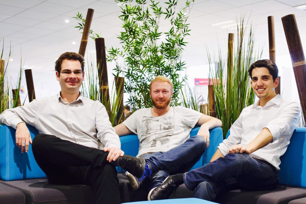
The 3DTrust team cofounders: (L-R) Andrei Mituca, Alexandre Guérin and Antoine Jeol.

When the team partially located to Toulouse for the accelerator program, they were confronted with the challenges that Airbus and its suppliers have. Of course, security is important in commercial aviation, but, other factors, such as traceability, are also of extreme concern. Aviation firms always need to know where parts come from, when they are made, by whom, in what orientation, with which batch of material, on which machine, etc. The team also saw just how many production steps 3D printing for manufacturing required.

Another 3DTrust cofounder I spoke to is Alexandre Guérin, who came from Siemens where he worked at that company’s VC arm. Guérin said that, at many manufacturing companies, the 3DTrust team saw challenges in the “scheduling of production, especially since scheduling and tracking was a manual step, often done with post-its or in Excel.”

The team had to first understand what it took to conduct day-to-day manufacturing with 3D printing. By working with manufacturers, they gained a more in-depth understanding that let them develop their software to work on and with the shop floor. They had to get their software to work with the most popular brands of industrial AM equipment to read and collate data from each of them.

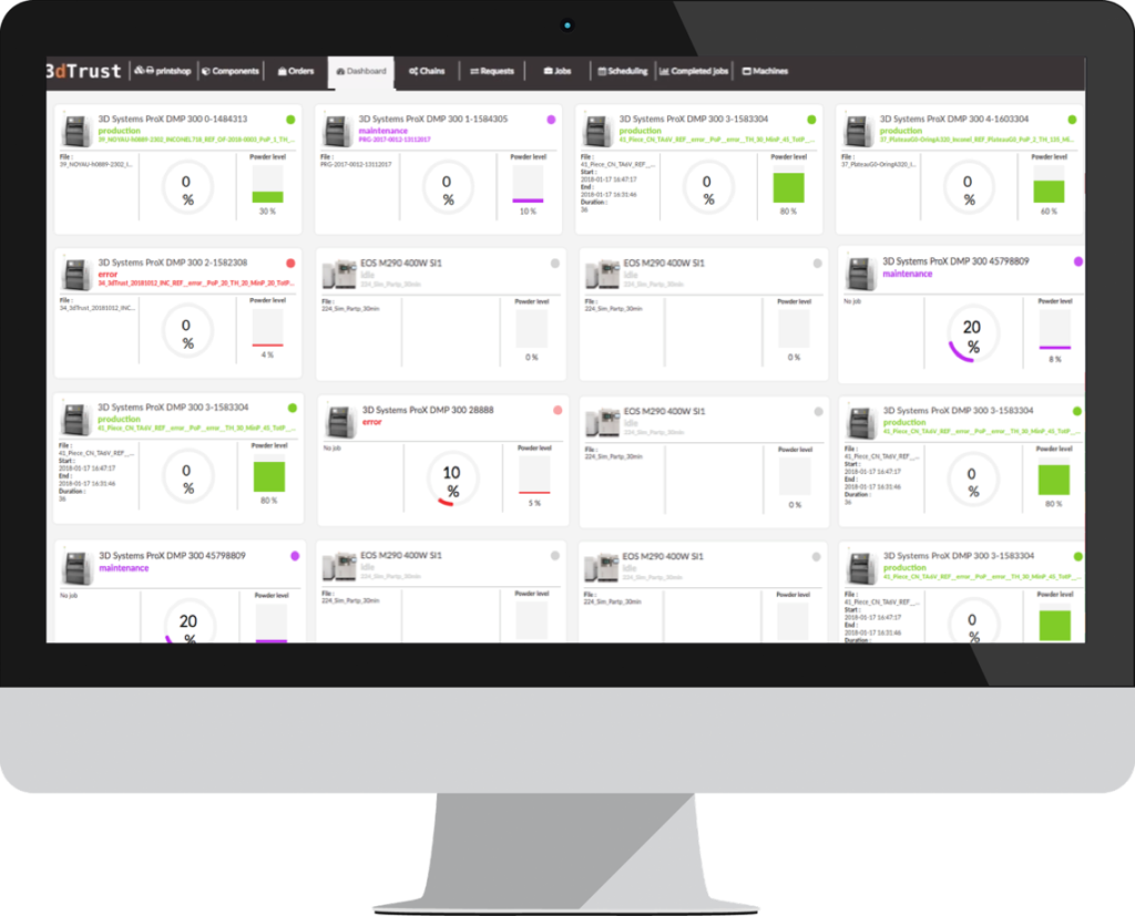
“It could be much more efficient if this tracking was done in software and future job planning was done algorithmically…with reduced human error…resulting in more parts being delivered on time,” Guérin said. “[We had to connect] with EOS, Renishaw, SLM Systems, Stratasys, AddUp and 3D Systems machines… to monitor every machine. If a machine stops, the error notification will get tracked in the software, which can analyze historical trends, detect mistakes, monitor gas levels, get real-time temperatures, receive notifications for specific events, get utilization data and performance data as well.”

With 3DTrust, a user can subscribe to a single machine or multiple machines to only receive the data relevant to them.

Making accessible all of that manufacturing data, scheduling, optimizing, and ensuring traceability is really what the company does now. Jeol believes that every AM machine should be connected and that, while there is a lot of data, in order to achieve true Industry 4.0 process control, that data has to be extracted from all of the connected systems and well managed. Once this happens, 3DTrust can perform traceability, productivity optimization, and analyze entire fleets of additive systems producing parts on time, as well as the post-production steps, to decide what should be done.

In response to client needs, they developed two entirely different architectures. In one, all of their software can be deployed locally, through ethernet cables and customer servers. In the other, Hybrid system, all of the file data is stored locally, but information—such as sensor values—is shared in the company’s cloud. The former version would be especially useful for defense and aviation companies, a group that has traditionally been wi-fi adverse. 3DTrust offers these tools in the form of software-as-a-service, with the company charging $650 per month per machine, although university and large installation pricing are also available. The setup consists of one to three days, typically with 3DTrust often conducting an on-site training for staff of two days.

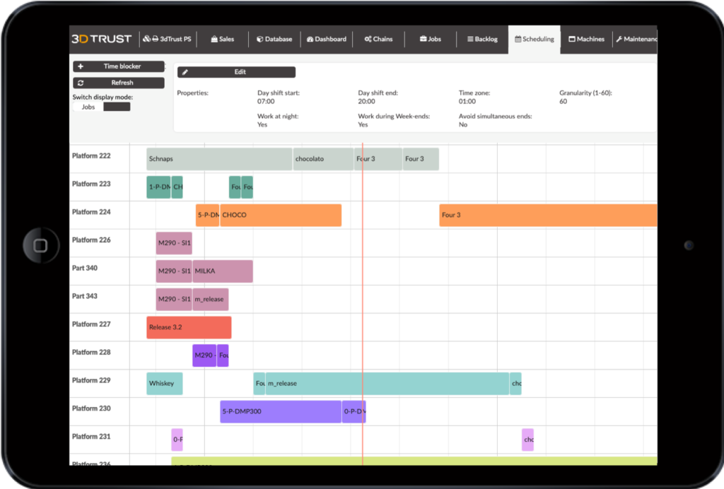
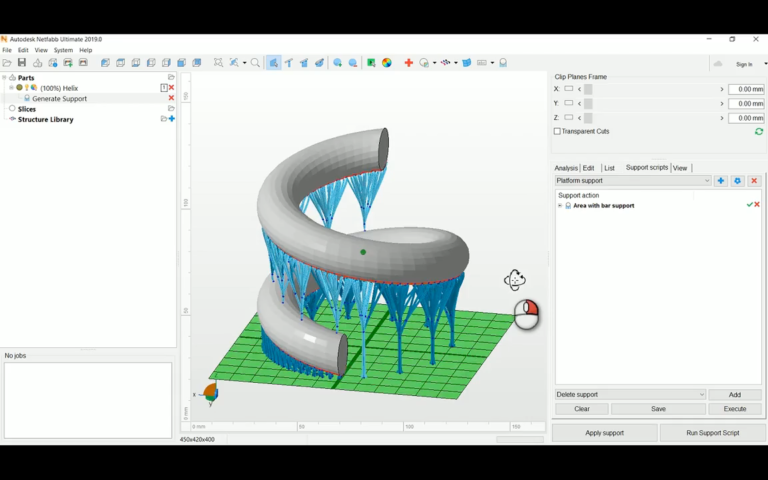
Users can view individual machine data, aggregate data or dive into individual build plates. They can upload STL or CAD files and queue jobs; files can also be downloaded and re-uploaded from Magics and Netfabb so it is possible to continue to use a preferred file-checking solution in tandem with the software. The output is a specific job file for a user’s particular machine. One could store files in the cloud and schedule or assign files or build platforms to machines or series of post-processing steps. Adjustments in print quality, results, machine utilization, status updates, and part traceability all happen in the software. Users can see delivery dates, materials, and add notes to files and jobs. It can be used in a service environment, in manufacturing or as an internal shared service for large firms.

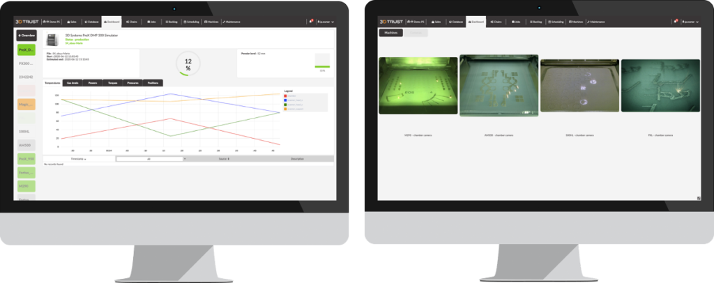
Through drilling down into each process, machine, and job users can get very granular data, but they can also see performance across time series or analyze all of the alerts and events that delayed builds. One can interface with onboard cameras in printers to check errors and look at individual layers as they are being built, as well.

Jeol said that initially, “We focused on a few key customers in medical, automotive and aerospace to make those customers happy. Making [the software] in conjunction with the guys on the shop floor every day helped us bring value to customers.”

Guérin believes that their customers are using data to get parts made right the first time in AM.

Guérin said, “Optimizing planning saves costs, makes the machines and processes more efficient, faster and cheaper, letting customers industrialize their technology for true serial production.”

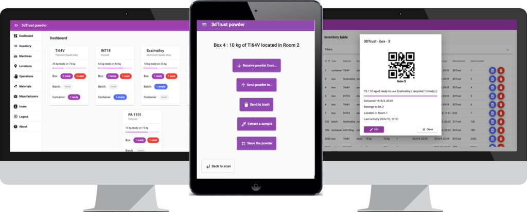
In addition to its flagship product, the 3DTrust team has just released a powder management solution. I was very excited about this since, for metals, powder management is key to getting good outcomes in prints, especially for manufacturing. Powder management is essential, but very tedious and time-consuming, especially in highly regulated environments. With the company’s new tool, users can track powder, do inventory management, and use a system that makes tracking easier and more robust as a process.

Meant mainly for large manufacturing companies, but also for universities, the software has some convenient tricks such as a QR print-and-read functionality that lets users stick their own labels on everything. I know from acquaintances that the profusion or lack of labels is often an annoyance. Now, handheld or phone-based scanners can read a production line or lab’s own QR barcodes to quickly tell them about a box, jar or pellet. The system lets users see quantities, dates, materials, storage conditions and availability.

Jeol mentioned that It also enables you to run a “genealogy, a family tree, to see, based on a part, where it came from, with which powder, where it was stored, where it was made, and in which boxes.” It can also be used to track samples or batch tests, with users then able to go back to identify parts or powders that failed tests. Users can also rely on scheduling tools to monitor how often a powder is recycled and combine it with job scheduling, so that a planned job is not able to use a powder recycled more than four times, for example. I’m very bullish on 3DTrust’s powder management tool and would recommend looking at it if you work in a production metal printing environment. It seems to be an intuitive, time-saving piece of technology.

The post 3DTrust Releases Intelligent Powder Management Solution for Quality Control appeared first on 3DPrint.com | The Voice of 3D Printing / Additive Manufacturing.

Link3D expands EOS partnership, enters collaboration with Autodesk and AMFG

New York-based additive manufacturing workflow software provider Link3D has expanded its partnership with EOS, a leading German 3D printer OEM. Working in a joint machine connectivity program, the two partners are enhancing Link3D’s Production Scheduling software to help streamline the additive manufacturing process. Additionally, Link3D has entered into a collaboration Autodesk and AMFG to enable full traceability […]

Reducing 3D Printing Collisions with Toolpath Optimization Methodology

While many industries are using 3D printing to manufacture products, the technology has not been largely adopted in large-scale production. According to researchers from the University of Arkansas Department of Industrial Engineering, this is mainly due to cycle time. However, while it’s possible to print different parts of one object at the same time thanks to multiple collaborating printheads, this isn’t yet widely supported by research. Hieu Bui, Harry A. Pierson, Sarah G. Nurre, and Kelly M. Sullivan published a paper, titled “Tool Path Planning Optimization for Multi-Tool Additive Manufacturing,” that lays out their proposed toolpath optimization methodology.

The abstract states, “The objectives are to create a collision-free infill toolpath for each printhead while maintaining the mechanical performance and geometric accuracy of the printed object. The methodology utilizes the combination of tabu search and novel collision detection and resolution algorithms, TS-CCR. The performance of the TS-CCR is analyzed and compared with the current industry standard.”

The FFF 3D printing process is limited by how fast the printhead is able to move, melt, and dispense filament. The parallel processing method, which lets multiple toolheads work together at the same time to fabricate different parts of the same object, is used by the Autodesk Netfabb software function for Project Escher 3D printers. This can obviously speed up printing time, but also increases the chance for collisions.

Netfabb uses an algorithm to make sure that all the printheads are synchronized, so they can’t collide with each other.

Summary of the result from the case study of Netfabb’s performance and toolpath illustrations (30% infill) of the Netfabb method and proposed method.

 The goal of this methodology is to consider collision constraints for 2-gantry 3D printers, while also minimizing the single layer makespan (printing time). 

The shortcomings of current methods, the lack of published research on concurrent FFF, and the need for an alternative path-planning method for multi-gantry FFF 3D printers inspired the development of a new method,” the researchers explained. “Although the multi-gantry system is one of several kinematic configurations of concurrent FFF 3D printing, increased understanding it can provide insights into the development of generalized multi-tool path planning problems for AM processes.”

A Tabu Search (TS) heuristic (practical method of problem solving), which uses a memory mechanism to store information to help guide future searches, was used to optimize the single layer makespan in the methodology by adjusting the toolpath for the infill. The TS incorporates three main operators:

  1. The local swap operator swaps two raster segments printed by the same printhead to reduce the rapid movement distance
  2. The global swap operator exchanges two raster segments that have been printed from different printheads
  3. The rebalancing operator allocates one raster segment from the printhead with a higher makespan to the other printhead

a) trajectory plot produced by the collision checking algorithm (tested layer A with 1% infill) showing 4 possible collisions (i.e. vertical gray bars); b) trajectory plot after adding 3 seconds’ delay to resolve the first collision (note that it also resolves the following collisions); c) toolpath representations of solution in 2b. The arrows indicate the two gantries are moving in the opposite directions toward each other when printing the associated raster segments. By adding 3 seconds delay at the dwell location, the two gantries synchronized and avoided the potential collision.

“At the beginning of the algorithm, with a randomized initial solution list, the global swap operator is favored. Due to the high degree of randomization of the sequence and the high number of collisions, adding delays might not be able to resolve the collisions, in which case the two gantries will work in sequential order. The goal is to segment the appropriate raster segments into two groups, one group for each printhead. The number of collisions begins to decrease as a result. Later on, the local swap slowly becomes more attractive.”

Two complementary algorithms work with the TS: a collision checking algorithm, which detects any potential collisions, and a collision response algorithm, which finds points in the toolpaths where a collision can be avoided by adding a delay.

The researchers explained, “An efficient collision checking algorithm should be able to quickly detect the collisions for a large number of raster segments and identify the corresponding movements that caused them. By utilizing a unique characteristic of the multi-gantry FFF machine, the process of identifying the collisions can be simplified. In such configuration, the collisions happen every time the gantries collide in the x-direction. In other words, a collision happens when the two gantries share the same workspace at any moment in time. A safety distance between two gantries was added when constructing the trajectory plot as a way to keep the gantries away from each other even though the collision is detected.”

Flowchart of collision checking algorithm

“The motivation of the collision response algorithm is to identify an opportunity for resolving the collision by adding a delay. It is worth mentioning that each vertex on the trajectory plot represents a potential place to insert the delay.”

This algorithm has 4 steps, the first being to identify a set of line segments that are associated with the first collision, and then figuring out whether a delay could fix the collision. Third, the delay is inserted and all future trajectory segments are adjusted, and finally, you move up in time to find the next collision; then, lather, rinse, repeat until the collisions are gone.

The team’s methodology for avoiding 3D printing collisions was thus named Tabu Search with collision checking and response, or TS-CCR.

“The TS-CCR outputs a solution represented as a combined list of sequences of raster segments that must be printed for each printhead,” the researchers wrote. “To get the infill makespan of the solution, an infill toolpath for each printhead is constructed from the aforementioned solution. The collision-checking algorithm then searches for any potential collisions and passes the information to the collision-response algorithm, which introduces delays in order to prevent potential collisions.”

a) tested layer A; b) turbine blade layer; c) engine block layer; d) wheel rim layer. The wheel rim layer is considered a special case since Netfabb did not produce a solution.

To test the TS-CCR’s performance, the team chose four objects, then sliced a selected layer of 0.3 mm from each and computed the results from the theoretical minimum makespan, slicing the layer with the Netfabb Multi-Gantry FFF Engine and the 2018.1.0 Escher plugin, and the TS-CCR.

They collected information, such as build volume and print speed, about the multi gantry 3D printer from the Titan Cronus profile in Netfabb.

For the TS heuristic, the value for the size of the candidate list and tabu tenure were chosen as 10 and 4, respectively. The algorithm terminates if it has been running for 2 minutes since the last improvement,” the researchers explained.

Then, they compared the makespan for three solutions – the theoretical minimum, proposed methodology, and Netfabb for 2 printheads – in a trajectory plot, which shows how the algorithms performed. 55 seconds of delays were added at different points, but because most of these were introduced in the printhead with a shorter makespan, only three total seconds were added to the overall makespan. This plot also shows how important the rebalancing operator is in TS – the gantries completed their work at almost the same time.

Trajectory plot of the result obtained from the TS-CCR (engine block layer with 30% infill). The printing time of the two gantries are 1272 and 1269 seconds, respectively.

“The performance of the methodology varies depending on the complexity of the layer. It can reduce the makespan of the “tested layer A” by 14.48% as compared to Netfabb, while the improvement reduces to 10.18% for the “engine block” layer. Since only one printhead is utilized to print the perimeter shells, the time spent on printing the shells likely offsets the improvement of the proposed methodology for any complex layer. Since this work focuses on only optimizing the infill, the method of allowing multiple printheads to print the perimeter shell at the same time can be implemented to reduce the makespan further,” the researchers wrote.

While there are only about 11 minutes of makespan reduction for the tested layer over the single printhead, this kind of improvement can accumulate across all layers and reduce the overall time.

a) makespan comparison for 3 layers (tested layer A, engine block, turbine blade) at 30% infill, where the proposed method can yield a solution with a shorter makespan than the solution obtained from Netfabb; b) makespan comparison for the “wheel rim” layer, where Netfabb did not produce a solution. The result from the methodology is compared to the makespan if the same layer is printed by the single printhead and the theoretical minimum.

The team’s proposed TS-CCR methodology can solve major issues of using multi-gantry FFF 3D printing, such as carefully planning to avoid mutual collisions while also not compromising the strength of the final print.

Discuss this and other 3D printing topics at 3DPrintBoard.com or share your thoughts below. 

The post Reducing 3D Printing Collisions with Toolpath Optimization Methodology appeared first on 3DPrint.com | The Voice of 3D Printing / Additive Manufacturing.

UK Researchers Inspired by Astrophysics to Improve Imaging for 3D Printed Models

Like cancer, heart disease and the many conditions surrounding it (along with other related systems in the human body) can often cause fatal complications, leading researchers around the world to continually look for better methods in diagnosing, treatment, and surgical procedures. UK researchers, I. Brewis and J.A. McLaughlin, at Northumbria University have recently explored 3D imaging in reference to cardiovascular health care, publishing their findings in ‘Improved Visualisation of Patient-Specific Heart Structure Using Three-Dimensional Printing Coupled with Image-Processing Techniques Inspired by Astrophysical Methods.’

Brewis and McLaughlin are working in the realm of astrophysics in creating new image-processing techniques for viewing the human heart, transferring the data to an .stl file and then 3D printing a medical model. These new techniques allow for better modeling from scans, especially improving on the clarity of smaller features.

Traditionally, CT and MRI scans have supplied data for 3D printed models. As the authors of the study point out, these are ‘relatively accurate’ but still produce errors. Not only that, image processing can be a high-maintenance venture, consuming both time and money. Currently there are a range of techniques in use, including:

  • Vignetting
  • Boxcar smoothing function
  • Dilation
  • Edge detection
  • Pixel plate scale development for charge-coupled devices on spacecraft

Brewis and McLaughlin examined whether using techniques generally used in astrophysics could reduce the margin of error, along with faster turnaround time in rendering. The basic steps in arriving at a 3D model must include acquiring data, segmenting, converting files, fixing and design, and 3D printing. For the purposes of this study, the scientists used data from one anonymous patient, obtaining 856 CT images. In segmentation they were able to identify the ‘region of interest’ to be 3D printed: the heart tissue.

Segmented heart data following first thresholding of right heart region (left) and segmented heart data following second thresholding of right heart region (right). The right ventricle (bottom left) shows improved clarity of internal chamber segmentation following second thresholding

The team used Slicer to view the chest cavity from multiple angles and cut all extraneous data for a better view.

“Initial thresholding highlighted all heart tissue, with the inclusion of deoxygenated blood in both the right atrium and right ventricle,” stated the researchers in their paper. “Areas of deoxygenated blood were found to be removed by applying a second threshold in the range [-600, 70] to the chambers of the right heart.”

A second pass of thresholding resulted in converting data from 2D segments into a 3D rendering.

“This method, whilst modelling the majority of the heart’s internal structure, omitted small-scale features such as valves. In order to extract these small-scale features from the DICOM data available, an alternative approach was introduced,” stated the researchers, upon using vignetting to eliminated added interference in the background.

Netfabb image processing stages from left to right initial and divided models

Further highlighting and enhancement allowed the research team to see areas of aortic valve cusp occlusion and areas of bad pixels more clearly.

“For both the full heart and the aortal valve, the total time taken for image segmentation was on the order of tens of minutes, where some parts of the segmentation process were, naturally, more time-consuming than others,” stated the researchers. “For the method presented here, the main time-consuming step was whilst utilizing Slicer 4.8.1’s in-built eraser and draw tools.”

Once the researchers had the files for both the heart and aortic valve models ready, they used Netfabb to prep for production with an SLA 3D printer.

“The SLA printer produced more sturdy 3D models yet could not produce models which did not require additional support in order to maintain the desired structure of the internal heart chambers (i.e. free standing models) during printing,” stated the researchers. “For a simple and relatively flat structure however, such as the aortic valve, the free standing issue was not a concern and the stronger resin-based model proved to be ideal for producing thin and delicate structures such as the tricuspid valve.”

Ultimately, the team produced a 3D printed heart model with four clearly defined heart chambers, along with the aorta, superior vena cava and the pulmonary vein and artery. The patient whose data the researchers were using as an example had an aortic aneurysm that is accurately depicted in the model, seen as an area of depression in an aortic side wall. Calcification can be clearly observed too, and this type of accuracy means surgeons can operate more precisely and efficiently, saving on time in the operating room.

“The use of 3D renderings of patient data improves on traditional imaging techniques where surgeons are required to visualise a three-dimensional picture of heart defects based on a series of 2D scans by reproducing exact, real three-dimensional cardiovascular anatomy,” state the researchers. “The use of 3D modelling can also improve the physician’s understanding of individual patient anatomy such as in the case of valve replacement16 or in procedural planning for the treatment of congenital heart disease.”

What do you think of this news? Let us know your thoughts! Join the discussion of this and other 3D printing topics at 3DPrintBoard.com.

[Source / Images: ‘Improved Visualisation of Patient-Specific Heart Structure Using Three-Dimensional Printing Coupled with Image-Processing Techniques Inspired by Astrophysical Methods’]

3D printed heart models. (left) complete heart model, (right) aortic valve
model). UK one pound coin for scale.


Interview with Alexander Oster of Autodesk

Alexander Oster is an extremely knowledgeable 3D printing person. If we’re looking at mesh repair or 3D printing files & software I’d consider Alexander the number one person worldwide. He also has a lot of manufacturing experience and this combined with his thorough knowledge of 3D printing software means he’s a veritable one man army in 3D printing. Alexander got started at one of the first 3D Printing service bureaus FIT (who pioneered SLA prototyping, prosthetics and manufacturing with 3D printing) singlehandedly wrote most of Netfabb and worked on some of the earliest 3D printing checking and pricing software. When Netfabb was acquired by Autodesk he moved to the company to become their Director of Additive Manufacturing. Alex is a great guy as well and has some very real nuanced insight to share with us.

Alexander Oster

How did you get into 3D printing? 

I came in contact with 3D printers for the first time in 1998, when I had a student job at a local company that acted as Prototyping Service Provider for the Southern German Automotive Industry. At the time, they used this completely new and mind-blowing technology called Stereolithography in order to make prototypes and molds for investment casting.

The new thing about this method was that overnight it transformed the old craftmanship of model-making into a completely digital and high-tech activity – and there was almost no existing software stack available that would support this change. I had a good chunk of experience in programming 3D games, experience which we leveraged to help write a lot of in house software to keep the process working and efficient.
This company, FIT AG, still exists today and has become one of the premier additive contract manufacturers in Europe.

You wrote one of the first online software for 3D printing, what was that like? 

Back in 2004, we mostly focused on the Design and Manufacturing of latticed part geometries years before everybody else sold this as “news”. For example, at the annual Euromold trade show 2006 we had a real size (about 3x3x3 meter) latticed tree on display – which was printed in Nylon and very lightweight due to its nature-inspired internal geometries.

It was unthinkable to do this in a CAD system at the time, so we had to find some shortcuts to directly create laser paths for use by the EOS plastic systems to handle the data appropriately.

But for our original geometry representation we still used (as did everybody else) triangles that were stored in the STL format. As this created a lot of instabilities and handling problems, we were forced to develop repair and fixing algorithms to mediate that. At this point, we did not make a commercially sellable product, but it was enough to be useful for others. So we released it as cloud service, and then cooperated with the newly founded Shapeways to streamline their customer upload process.

By coincidence this was also the time when the RepRap project and especially a small New York startup called Makerbot set out to make 3D Printing a known technology for the masses. Like in the industrial world, each one of those new 3D Printer users had a dire need to process all kinds of broken and invalid geometry files from a plethora sources – and this made the netfabb Cloud Services quite popular.
After a few years, we were very honored and excited that Microsoft took up the service as one of the first on their Azure platform; and connected it to the newly released Windows 10, with its built-in 3D Builder app.

You also wrote Netfabb, how has its functionality expanded? 

Netfabb was the desktop version of this cloud service, and today has grown from a small tool that prepared STL files for 3D printing to a fully blown end to end solution for Additive Manufacturing. Particularly since our acquisition by Autodesk, we were able to quickly leverage the full force of a software giant and incorporate CAD kernels, Metal Process Simulation, Finite Element Solver, and advanced cloud capabilities. The whole software is now a puzzle piece in the much larger Autodesk Manufacturing world consisting of top-end vertical solutions for all each imaginable process of Digital Manufacturing – whether it be CNC operations (Autodesk PowerMill), composite manufacturing and cutting (Autodesk TruNest), or injection molding simulation (Autodesk MoldFlow).

This broadness of capabilities makes the Autodesk solution portfolio very unique in the market, and our tiered packaging model really has changed various developments in the industry. For example, at an entry-level price of only 200 US dollars per year we directly support hundreds of different 3D printers, affordable providing everybody in an organization access to 3D Printing data preparation. At the same time our high-end manufacturing and simulation solutions power the most advanced industrial applications on the planet.

What has changed in 3D printing industry during the time you were involved with it? Is the software landscape different now?

The major change between today and a decade ago is that nowadays a lot of large industrial players are investing huge amounts of capital, and new startups easily receive millions of dollars of venture funding with a well-presented idea that only exists on paper.

I am not sure if this is as bad as in other areas like Blockchain or Artificial Intelligence – but it has in my opinion skewed the market quite a lot and we are often seeing behind the scenes new entrants that are remaking all the mistakes that have already been made 10 years ago. This sometimes makes one feel sorry for all the lost money, but it also ensures that life stays exciting and it is not absolute that the most capital equipped player will in the end win the market.

From a software perspective, we are basically seeing what some people have predicted long time ago, which is basically the fact that the major large CAD vendors moved in and are incorporating 3D printing solutions into their products – and will in the long term dominate the software field. This is kind of unavoidable due to the important link between the design process of parts and the manufacturability constraints that naturally come with Additive Manufacturing.

What are Autodesk’s plans with 3D printing? 

In addition to all of our Netfabb activities, I am specifically excited about our movement to integrate our manufacturing capabilities into Fusion 360. Fusion 360 is Autodesk’s next generation cloud-connected Design-to-Make platform, supporting all steps of the product development process, from conceptual design, mechanical design, CAE, CAM, and data management. And all of this backed by a cloud system that makes collaboration across different continents as effective as sitting next to each other.

A few months ago, we have released the first iteration of our Metal Additive capabilities inside of Fusion 360. Next to the established Fusion CAM module, this gives an amazing in-CAD experience for the user to quickly get from a design environment to a print ready file within seconds, and at the same time create the CNC postprocessing operation for the same part.

It is truly exciting to see the possibilities and the convergence of the design process of a product with the downstream manufacturing chain. And all of this in one place and in an associative way – which means once there is a change done upstream to the original design the manufacturing instructions are automatically updated accordingly. And all of this can be accessed at a subscription prices that will open up those capabilities to a vast group of designers and engineers who could not have afforded a fraction of capabilities before.

What do you see as the major roadblocks to 3D printing adoption?

While a lot of people still think about the quality aspects of Additive Manufacturing as the main issue, in my opinion the problem is more that the current cost structure of the technologies is far too expensive to make them viable in the mainstream. If the costs per part would be significantly lower, a lot of applications would open up where the quality problems we are seeing would be less relevant – casting for example has at least as many issues as additive, but is viable and widely used.

A lot of companies today are trying to reduce the costs by increasing production speed. This certainly helps, but in my opinion the real elephant in the room is the capital investment needed to really make use of the technology. You can easily find an entry level CNC equipment, and industrial robot or a state of the art injection molding machine for less than 50.000 US dollars, but one still requires millions of dollars to set up an efficient Additive Manufacturing operation, and even more millions to train engineers to properly take advantage of the process. Based on the amount of capital, this often means a lot of produced parts must be producted in order to amortize and therefore creates a high barrier for applications that are most suitable for 3D printing (i.e. the ones that have a low life time unit count).

The big democratization of 3D Printing has already occurred for stereolithography and FDM market, and I am sure we will also see it for the more industrial technologies too. And it will finally make the technology mainstream enough that the knowledge about them becomes ubiquitous.

What advice would you give me if I was an industrial company wanting to get started with 3D printing?

Do not invest millions of dollars in a in house technology park that will be outdated in a few years. Rather invest the money in product development together with a manufacturing partner and design consultants that can train you how to apply 3D Printing in the best way for your application.

How do you think that 3D printing could make a real impact on companies bottom lines?

I think this is not the right question, as this is always suggesting that we will build current products just a little bit cheaper when we 3D print them. In my opinion, the real question is much more which developments will not happen and which new businesses cannot be built without a major contribution of 3D Printing technology. And there the list is quite extensive.

I do not believe patient-specific implants are feasible without 3D Printing. I also believe there will be no walking robots without 3D printed components and no flying taxis. Or if you look at the current developments in the aerospace industry, we will not go to Mars without Additive Manufacturing involved, nor will we achieve environmentally sustainable air travel. Climate Change challenges, in general, will be very hard to tackle. If you look at the construction market for example, the amount of buildings the world needs to build in the coming decades for the billions of people moving into the middle class is mind-blowing. Neither enough resources nor the human capacity exists today to achieve this without destroying the planet. I do not believe that this will work out without proper automation, and advances in robotics and 3D printing will certainly play a key role in this. Dubai for example recently passed a law that 25% of its new buildings need to be 3D printed by 2025.
Independent how that will turn out, the future certainly will be exciting.

Stratasys goes direct from CAD to 3D print with GrabCAD Print Advanced FDM

With the help of GrabCAD Print, a cloud-based CAD software, Stratasys 3D printers can now go directly from CAD to print, thus removing the conversion to mesh file step to streamline the workflow. Mark Walker, Stratasys’ Lead Software Product Manager explained, “For design and manufacturing engineers, one of the most frustrating processes is ‘dumbing down’ a […]

Walkthrough of new features in Autodesk Netfabb 2019

Recently, award winning software company Autodesk released a major update of its additive manufacturing and design software Netfabb. In this article, we take a walk-through the latest additions in Netfabb 2019 discovering the improvements made to productivity, and checking out some of the software’s most powerful features. Highlights of Netfabb 2019: – Cloud-based metal powder […]

Cloud-Based Simulation and More Among New Features in Netfabb 2019

Netfabb has been a popular software program even since before it was acquired by Autodesk, and each year it offers more and more features to its users as Autodesk brings out new versions. Recently, Autodesk introduced Netfabb 2019, which has several new features in addition to updates to some of its existing features. The new release focuses on improved productivity and updates the simulation and latticing, two of the software’s most significant features.

Simulation is a critical part of the additive manufacturing process, particularly metal additive manufacturing. It saves time and materials by allowing the user to run through a process before running it for real, and to smooth out any issues that the software predicts. Netfabb subscribers beginning at the Premium tier can now take advantage of cloud-based, multi-scale, metal powder bed process simulation.

“With metal additive manufacturing, the stakes are high. Materials are expensive and lead times are continually compressed,” says Autodesk. “The ability to anticipate your outcomes can often save the day, and the project. From additive consultancies to industrial innovation labs and research facilities, industry leaders turn to Netfabb Simulation.  Now, this same simulation capability is available in the cloud, allowing you the ability to pay for simulation only when you need it.”

Netfabb simulation uses a multi-scale modelling approach. Users can input machine parameters and material properties to develop their PRM files, then simulate large, complex parts “with a fully predictive part-scale simulation which captures the complex thermal and mechanical interaction between parts during the build process,” says Autodesk. The cloud credit cost for a PRM file is fixed, but part-scale simulation depends on the complexity of the parts being submitted.

In addition, the PRM library has been redesigned to give the user visibility into process parameters. PRM files can now be edited directly from the library.

Manual latticing is now available to customers at the Premium tier, and all Netfabb lattice functionality is now available from a single location. Additional updates allow for better productivity, such as:

  • A replay function that allows regeneration of manual or script-based supports after a change in geometry is made, even after the support strategy has been finalized.
  • Supports can be deleted by criteria
  • Shared viewing and cloud storage
  • A new My Machines workspace that streamlines the process by allowing the user to define only the machines they have access to. The user can also categorize machines by functions and assign repair or support scripts accordingly.

Netfabb 2019 also includes a new workspace for the DMG Mori Lasertec 30 and features updated Form2 integration, giving the user direct access to Form2 from Netfabb.

That’s only a few of the new and updated features that Netfabb 2019 offers – for a full list, you can find out more here.

Discuss this and other 3D printing topics at 3DPrintBoard.com or share your thoughts below. 

[Source/Images: Autodesk]


Team Effort Uses 3D Printing to Restore Coral Reefs

[Image: SECORE: Paul Selvaggio]

Coral reefs are the most diverse ecosystems on Earth, with thousands of animal and plant species living in their colorful ocean-floor habitats. These reefs are in quite a bit of trouble currently, however. In the past 30 years, 50 percent of the world’s coral reefs have died and if changes aren’t made to slow the progression of climate change and curb other human-caused damage to the reefs, 90 percent of them may die in the next century. Coral reefs aren’t just vital to the plants and animals that call them home, but to humans as well – they provide a lot of income through tourism and fishing, as well as protecting coastlines during violent storms.

Saving them, therefore, is critical, and involves some human intervention at this point. Coral are sessile animals, meaning that they take root like plants but capture their food from the ocean water. Coral polyps root themselves in ocean rocks, gradually reproducing and growing until they form the lush, brightly colored reefs that people travel thousands of miles to see. It’s a slow process, though – coral reefs grow by centimeters each year, taking thousands of years to become large and thriving. Right now, coral reefs don’t have thousands of years, so they need our help.

Several organizations have been trying to help coral by 3D printing artificial reefs and sinking them in the ocean in hopes of attracting free-floating coral polyps to embed themselves and begin reproducing. An organization called SECORE International (Sexual Coral Reproduction) is also using 3D printing, but taking a more hands-on, aggressive approach. SECORE is a nonprofit global network of scientists, public aquarium professionals and local stakeholders working to protect and restore coral reefs. Along with its partners, which include the California Academy of Sciences (CAS) and the Nature Conservancy, SECORE is developing restoration processes that leverage the natural reproductive habits of coral.

3D printed seeding units. [Image: SECORE/Valérie Chamberland]

Certain coral species naturally broadcast egg and sperm cells, which are collected by SECORE, fertilized, and then raised in tanks until they become freely swimming larvae. Those larvae are then introduced to 3D printed “seeding units” that resemble places on natural reefs where coral would attach. Once the coral have embedded themselves, the seeding units are planted on reef areas in need of restoration.

It’s an effective approach, but a costly one, unfortunately.

“One of the ways SECORE is aiming to reduce these costs is by designing seeding units that do not need to be manually attached to the reef, but rather can be sown from a boat or other method, similar to how a farmer would sow seeds in a field,” said SECORE Project and Workshop Manager Aric Bickel.

3D printing is another way to keep costs down, as well as to rapidly produce the seeding units. SECORE aims to produce a million of the units by 2021, and hundreds of thousands of units annually by then. Phase One of the project is taking place in the Caribbean, with research and training hubs in Mexico, Curaçao and the Bahamas.

“3D printing allows us to do a bit of rapid prototyping. We were looking at several different materials, and 3D printing allows us to print a variety of materials,” Bickel said. “It also saves the cost of having to make molds or castings which, particularly for the initial prototypes, would be a significant amount of money invested.”

A diver with a tray of the seeding units [Image: SECORE/Benjamin Mueller]

CAS is one of SECORE’s primary funding providers, and because SECORE is a small team with limited engineering capabilities, CAS turned to the Autodesk Foundation, with which it looked into various design firms for help with the development of the seeding units.

“In collaboration with the Foundation, we reached out to several design firms,” Bickel said. “Emerging Objects seemed like they would be the best folks to help us out with this next design phase and hopefully with the iterative design phases as we go forward.”

One of the main challenges SECORE has been having is finding the best material and design combination for the seeding units. Not just any shape can be used – the units need to be able to wedge themselves into the reefs without manual assistance. The material is an issue, too. SECORE had been using rough cement for the seeding units, but that material worked a little too well – in addition to attracting corals, it also attracted quite a few competing organisms.

“One issue was with competition from other species on the units themselves,” said Bickel. “What the trials showed is that a slicker surface will cut down on that potential competition. The needle that you have to thread here is having a surface that’s rough enough for corals to settle on and to attach to but smooth enough that it’s not a good location for other organisms such as sponges and algae to attach to.”

Several years of trials and experiments revealed ceramic to be a good potential material for the seeding units. Emerging Objects has plenty of experience in the experimental use of 3D printed ceramic, but needed to be able to 3D print the material on a large scale, so the company reached out to Boston Ceramics for help.

“Boston Ceramics is one of the few companies we’re aware of in the world that can potentially meet some of the demands for the number of substrates we’ll be using,” said Bickel.

The team used Autodesk Netfabb to design the original shape, a tetrapod, for the seeding units, and has been experimenting with other designs that are better suited to landing and wedging themselves in the surfaces of the reefs and protecting the larvae. One of those designs looks like a ninja throwing star.

[Image: SECORE/Valérie Chamberland]

“The question we posed to our working group was, ‘Can you give us your best impression of what promotes coral larvae to grow, and what’s going to allow them to survive in the ocean as they grow up in these early life stages?’” said Bickel.

The SECORE project is not one of immediate gratification. The organization grows its corals from embryos in small conglomerations of cells, and depending on the species, it can take several years for the corals to become sexually mature. In earlier life stages, however, the coral can still provide habitats for fish and other species.

This elkhorn coral was outplanted by SECORE five years ago. Since then, it has grown into a mature colony, which now spawns with other elkhorn colonies in the waters of Curaçao. [Image: SECORE/Paul Selvaggio]

“It’s definitely an investment in the future,” Bickel said. “I think that with really complicated ecosystems, we’re talking many years before you start seeing comparable structure return to areas that are being restored. The main focus at the moment is, can we improve our methods and our technologies to upscale this type of restoration to the levels needed to counteract the decline?”

SECORE isn’t the only organization working to do so, and the hope is that with enough of them putting effort into restoring coral reefs, the damage can be mitigated and even reversed.

Discuss this and other 3D printing topics at 3DPrintBoard.com or share your thoughts below.

[Source: Autodesk]