Take a look at the latest guide from Erin St. Blaine: build a three tiered chandelier with hanging DIY paper-craft crystals that light up with pixels inside. Easily add your own custom animations using CircuitPython and the LED Animations Library. This guide takes animated lights a step further, adding a rotary encoder knob that controls the brightness or the animation speed of the pixels, and also acts as an on/off switch. From the guide:
Floating crystals and glowing lights are a match made in heaven. This project combines a wide variety of skills and tools into one lovely project. Make a gorgeous hanging lamp with sparkly beads, glowing crystals, live edge wood and of course, lots of NeoPixels.
My chandelier is unique, and designed to show my personal style. Since you, dear reader, have your very own unique style, this tutorial will focus on giving you the tools to design and create your own one-of-a-kind bespoke hanging lamp. This tutorial will provide source files and ideas, and give guidance on how the electronics fit together.
This tutorial will also get you started with customizing your own software animations. The sample code uses CircuitPython and the delightfully easy to use LED Animations Library by Kattni Rembor. This code gives you a framework that allows speed and brightness control using a rotary encoder knob, so you can adjust the lighting to suit any environment or mood.
We all know how this works. The moment you stop watching your 3D print’s progress is the moment that the “transporter accident” (my favorite slang for a failed print) happens.
Spaghetti Detective is a web-based AI that monitors your prints (via a webcam) and alerts you if a print goes south, allowing the print to be paused or stopped.
The service is free for casual users and $4/month for daily printer use. Basically, it monitors your print by looking for patterns of spaghetti on the print bed.
In this video, Thomas Sanladerer reviews Spaghetti Detective by testing out a number of print situations to see how effective the AI is. What he found is that it needs a lot of learning to be more accurate. He still thinks, given its free (and cheap) options, it’s a great way to at least be able to monitor your print from anywhere. And given that it’s open source and that you can get print-hours credit by feeding back info on your prints, he has hope for the future of the tech.
Spaghetti Detective is an OctoPrint plug-in and they are working on a featuring, now in Beta, that would allow you to access all of OctoPrint’s functions remotely.
In partnership with the Air Force Research Laboratory (AFRL) and GE Research, the U.S. National Additive Manufacturing Innovation Institute America Makes has launched a ‘direct call-to-action’ challenge to the additive manufacturing (AM) industry. The Open Source-Additive Scanning Implementation Strategy (OASIS) Challenge, which has a prize pool of $68,000, is inviting entrants to submit innovative open-source […]
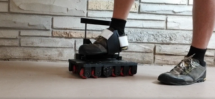
Alexander Evans, a maker and software engineer, could have the answer to completely immersive VR with his motorized shoes that feature mostly 3D printed parts, made on his Prusa systems. The shoes allow users to move omnidirectionally—each one has a track of horizontally facing wheels, and another track of vertically facing wheels. Each battery-powered shoe also features an attached motor, to help control movement.
Leg binding
“I’m making motorized shoes to be used with virtual reality games. The shoes keep you in the same spot as you walk, like a treadmill. You can walk infinitely in the game while staying in the same spot in the real world. The shoes are omni-directional so you can turn, strafe, and walk in any direction,” Evans wrote in his blog.
When wearing the heavy shoes, users can glide in multiple directions, and don’t even have to lift their feet off the ground. But, in order to wear them to play VR games, Evans says you also need to wear a safety harness that’s mounted to the ceiling or a strong, stable structure; this way, you don’t have to worry about rolling into a wall or, God forbid, out of a window.
First test with sideways motion
“These are basically roller skates that you wear with your eyes covered,” Evans commented on his Reddit post about the shoes. “If there is no safety structure in place, the user will fall and get hurt.”
They’re not so much shoes as they are motorized, wheeled platforms onto which you can strap your shoe-wearing feet. It would probably be pretty uncomfortable to put your bare feet on top of all that metal.
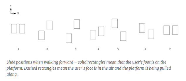
The way the design works is really interesting. Check out the image below:
The darker rectangle denotes a foot that is on the motorized platform, while the lighter rectangle signifies that the user is bringing the shoe forward or to the side with their foot. When the right foot is moved, a sensor in the platform detects an acceleration in the Y direction, which then triggers the motor on the left platform to turn on. The second shoe will begin moving backward at the same speed the first is moving forward.
“The speed to use can be calculated by using the accelerometer data (integrating to get the velocity) or by using motor encoders,” Evans wrote. “…When the user takes a step forward with his right foot, the left foot is moved at the same speed in the opposite direction.”
In terms of braking, when the user is standing still, both feet on the platform, the motors should resist any motion until one of the shoes is moved again. Check out the blog post if you want the nitty gritty details of the algorithms Evans is using for these shoes.
Right now, an Android app manually controls the shoes, but Evans is currently tweaking the software so movement can be automated and integrated within VR games. In the future, he hopes to add support for crouching and jogging to his design, though doesn’t believe that the shoes will be able to handle full-speed sprinting.
Evans doesn’t plan on licensing or patenting his shoes, though he wouldn’t mind selling them in the future once he’s perfected the design. In fact, he is a fan of the open source movement, and has added all the 3D printing files for the shoes onto GitHub, so others can download them and try to make their own pair of motorized shoes for immersive VR play.
“I plan on continuing to develop an open-source prototype while I build a YouTube channel. Once I have a sellable version, I plan on using the version for a couple months to see how well they last,” he explained on his blog. “I need to look into any safety regulations I need to meet, and get product liability insurance. I can produce a small batch of DIY kits and sell them. If they sell well, I can get another 3D printer or two and continue producing small batches and continue to build a 3D printer farm.”
Monitoring and quality control systems are becoming more widespread in additive manufacturing as a means of ensuring repeatability and aiming for first-time-right parts. A greater need for quality control are now trickling down to items that are more commonly made by the average consumer using FFF 3D printers, as detailed in “Open Source Computer Vision-based Layer-wise 3D Printing Analysis,” by Aliaksei L. Petsiuk and Joshua M. Pearce.
Dr. Joshua Pearce, an associate professor of materials science & engineering, and electrical & computer engineering at Michigan Technical University has performed extensive research into 3D printing, recyclability, and open-source platforms, along with protocrystallinity, photovoltaic technology, nanotechnology, and more.
As a proponent of 3D printing household items rather than purchasing them, Pearce foresees that the technology will infiltrate the mainstream and the average household much more deeply in the future. While there are many skeptics, this thinking is in line with many other tech visionaries who see great potential for 3D printing on all levels.
In a press release sent to 3DPrint.com, Pearce explains that quality control continues to be an issue at the household level—leading him to create a visual servoing platform for analysis in multi-stage image segmentation, preventing failure during AM, and tracking of errors both inside and out. In referring to previous research and development of quality control methods for “more mature areas of AM,” the authors realized that generally there is no “on-the-fly algorithm for compensating, correcting or eliminating manufacturing failures.
Analysis in Pearce’s program begins with side-view height validation, measuring both the external and internal structure. The approach is centered around repair-based actions, allowing users to enjoy all the benefits of 3D printing (speed, affordability, the ability to create and manufacture without a middleman, and more) without the headaches of wasted time and materials due to errors that could have been caught ahead of time. The overall goal is to “increase resiliency and quality” in FFF 3D printing.
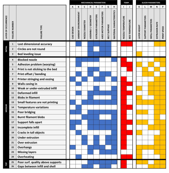
3D printing parameters allowing failure correction
“The developed framework analyzes both global (deformation of overall dimensions) and local (deformation of filling) deviations of print modes, it restores the level of scale and displacement of the deformed layer and introduces a potential opportunity of repairing internal defects in printed layers,” explain Petsiuk and Pearce in their paper.
Parameters such as the following can be controlled:
Temperature
Feed rate
Extruder speed
Height of layers
Line thickness
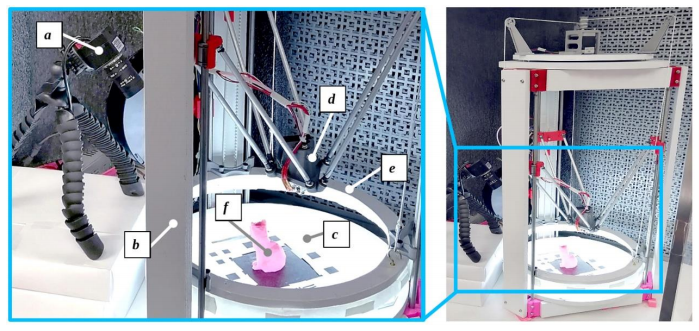
While in most cases it may be impossible to compensate for mechanical or design errors, a suitable algorithm can cut down on the number of print failures significantly. In this study, the authors used a Michigan Tech Open Sustainability Technology (MOST) Delta RepRap FFF-based 3D printer for testing on a fixed surface improving synchronization between the printer and camera, based on a 1/2.9 inch Sony IMX322 CMOS Image Sensor and capturing 1280×720 pixel frames at a frequency of 30 Hz.
Visual Servoing Platform: working area (left), printer assembly (right): a – camera; b – 3-D printer frame; c – visual marker plate on top of the printing bed; d – extruder; e – movable lighting frame; f – printed part.
Projective transformation of the G-Code and STL model applied to the source image frame: a – camera position relative to the STL model; b– G-Code trajectories projected on the source image frame. This and the following slides illustrate the printing analysis for a low polygonal fox model [63].
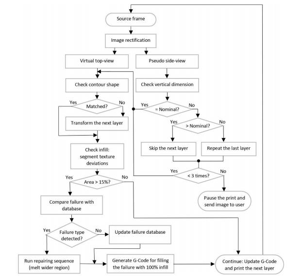
The algorithm monitors for printing errors with the one camera situated at an angle, watching layers being printed—along with viewing the model from the side:
“Thus, one source frame can be divided into a virtual top view from above and a pseudo-view from the side.”
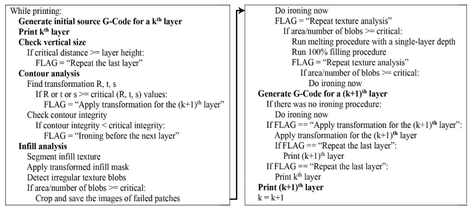
3D printing control algorithm
Currently, the study serves as a tool for optimizing efficiency in production via savings of time and material but should not be considered as a “full failure correction algorithm.”
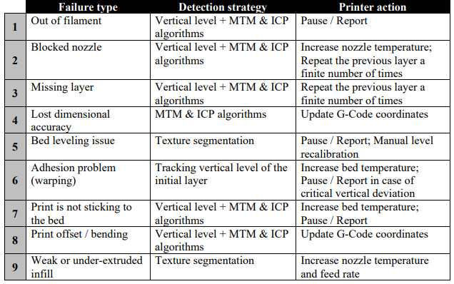
Example of failure correction
Interested in finding out more about how to use this open-source analysis program? Click here.
Two researchers from Michigan Technological University, Dr. Joshua Pearce and Aliaksei Petsiuk, have developed an open source, computer vision-based software algorithm capable of print failure detection and correction. Leveraging just a single camera pointed at the build plate, the code tracks – layer by layer – any printing errors that appear on the exterior or interior […]
Perennial 3D printing innovator and Professor at Michigan Technological University (MTU) Joshua Pearce, has teamed up with MTU colleague Jacob Franz, to create an open-source grinding machine for compression screw manufacturing. Dr Pearce, who has consistently championed the advancement of open-source 3D printing, led the project, which yielded a low-cost, easily replicable open-source machine. Reportedly […]
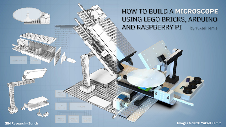
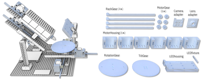
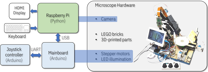
I always enjoy a good 3D printed DIY project, whether it’s truly helpful or just for fun. These projects are even cooler when you add Legos into the mix, like Reddit user DIY_Maxwell did. He posted about his work using 3D printing, Arduino, Raspberry Pi, and Lego bricks to make an open source, motorized microscope. But, the microscope itself is not fully 3D printed – instead, the body was built with Lego bricks and some 3D printed components. What makes this project more awesome is the stop motion-style video he made showing the various parts of the project and how they all fit together to make a working microscope.
“I wanted to have a modular microscope, something I can easily modify for transmitted-light, reflected-light, cross-section, etc. My early prototypes did not have Legos, as I started making my own interlocking pieces, I realized that I was in fact printing lego-like designs, I thought buying legos would be less of an effort,” he wrote on Reddit when asked why he didn’t 3D print all the parts. “Then I found out about these “sliding” lego pieces, which are very precise for linear actuators. The other advantage is that, if I want to change the height of the camera let’s say, I simply add more bricks, it’s convenient.”
DIY_maxwell used FreeCAD to design the 3D printed microscope parts, which were fabricated on an Ender 3 system. All of the source codes and design files have been provided open source on GitHub, along with detailed step-by-step instructions on how to make your own.
Before you jump right in, do you know what exactly a motorized microscope does when compared to a regular microscope? DIY_maxwell explained that, at least for him, it needed to be able to tilt in order to take photos, from an angle, of “highly reflective surfaces (semiconductor chips),” and that it should quickly adjust the focus and magnification, and position of the sample.
“The microscope has a simple operation principle based on changing the magnification and the focus by adjusting the relative distances between a camera, a single objective lens and a sample. Briefly, two linear stages with stepper motors are used to adjust these distances for a continuous and wide magnification range,” the GitHub instructions state. “Four additional stepper motors tilt the camera module and change the X-Y position and rotation of the sample. A uniform light source illuminates the sample either from an angle (reflected light) or from the bottom of the sample (transmitted light).”
The main components of this modular, motorized microscope include a Raspberry Pi system, an 8 MegaPixel camera, six stepper motors, a keyboard or joystick for variable speed control, uniform illumination, and obviously plenty of Lego bricks. Depending on the specific features and electronics vendors used, the whole thing costs between $200-$400, and once you have all the parts in front of you, should only take a couple of hours to assemble.
The main body was built with individually-purchased Lego bricks, and DIY_maxwell designed custom actuators and 3D printed them, rather than using available motors and gears from LEGO Technic.
“This approach not only lowered the cost of the microscope but also gave me some flexibility in the design and implementation of precise linear and rotary actuators. In principle, the whole structure could be 3D-printed without using any LEGO parts but that would be less modular and more time consuming,” he writes in GitHub.
In addition, 3D printing offers you the flexibility of quickly changing the design for maximum optimization if and when it’s needed.
“If the parts do not match well, some minor modification in the original design file (e.g. enlarging the holes matching to LEGO studs) or polishing/drilling may be required,” he explained.
The contents of the motorized microscope are as follows:
Linear Actuators
Camera Module
Rotary Stage
Illumination
Tilt Mechanism
Electronics
Final Assembly
Software
You can find detailed instructions, images, slicer settings, tips, and more on GitHub, and a longer version of the assembly video can be viewed here.
Several other Reddit users who routinely use microscopes related how impressed they were about the project; a geologist mentioned that “starting price can be anywhere between $500 to $1000 for something with that kind of quality” when DIY_maxwell said that his microscope could “easily resolve 10um features.” A pathologist expressed excitement about “a modular system to motorize common non motorized microscopes (Leica, Olympus, etc.).” While the compliment was appreciated by the maker, it was noted that “this microscope is not meant to replace a lab microscope used for medical assessment. No dark-field, no fluorescence, no aperture control, it suffers from chromatic aberration and other optical effects at high magnification, etc.”
“I hope this prototype persuades other DIY-enthusiasts to develop new designs of microscopes.”
If you’re interested in using 3D printing to make your own microscope, you can check out all of the relevant information on GitHub to build this one, or check out the OpenFlexture Microscope project on Wikifactory. This was created as “part of the Waterscope initiative, which by allowing for fast and affordable on-site bacterial testing of the water quality in developing regions of the world, is helping to cope with the diseases caused by bad quality water drinking.”
OpenFlexure Microscope
The OpenFlexure can be built in the classroom and used as an education tool for both students and teachers. Because the 3D printed microscope stage uses plastic flexures, the motion is free from friction and vibration, and the four-bar linkages in the stage can be 3D printed in a single job with no support material.
You can find other open source 3D printable microscopes on Thingiverse as well; happy making!
Discuss this and other 3D printing topics at 3DPrintBoard.com or share your thoughts below.
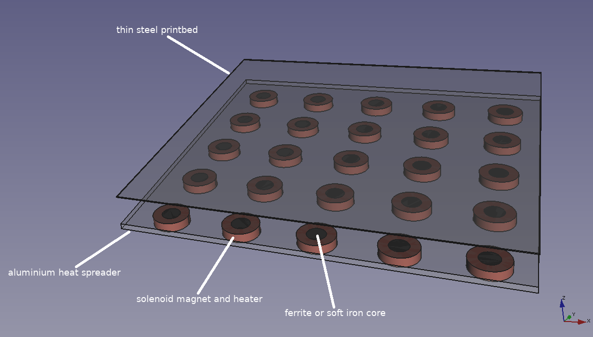
While his company, RepRap Ltd, provides open source, heavily-printable 3D printers, supplies and services online, Adrian Bowyer continues to invent and develop new ideas for open source 3D printing. The latest is a solenoid bed heater, a concept which Bowyer describes on his company blog.
Wanting to combine the concept of heated beds (invented by Chris Palmer aka “Nophead” in 2010) with removable steel sheets (invented by Josef Průša), RepRap inventor came up with a novel way to heat build platforms for material extrusion 3D printers. While heated beds ensure printed parts adhere to the build platform, removable sheets can be flexed to easily detach prints.
Bowyer’s diagram for a solenoid bed heater. Image courtesy of RepRap Ltd.
Bowyer’s idea is to use an electromagnetic attachment between the printer and the flexible sheet. The magnetic field holds the plate in place and is turned on or off when the printer’s bed heater is turned on or off. That way, once a print is finished, the magnets can be flicked off and the sheet can be removed. In the video below, YouTube user Kamera demonstrates how solenoids can be used to hold metal objects in place with an on/off switch.
He expands on this idea by imagining the printer’s hot end as a mechanism to push the flexible sheet off of the print platform when complete, making it possible for a new blank sheet to be loaded in order to begin a subsequent print. This process could be automated using a robotic arm similar to the method employed by Voodoo Manufacturing or we might imagine the printer’s extruder picking up a new sheet itself using a magnet or some other mechanism.
Bowyer envisions the solenoids under the bed powdered by pulse-width modulated electricity evened out by a capacitor acting as a low-pass filter. The magnets could then be operating continuously while the bed is heated, acting as both magnetic holders and heaters. For the flexible sheets, he hypothesizes the use of a ferromagnetic material that isn’t permanently magnetized so that the sheet doesn’t stick when the field is turned off. To see just how hot magnetic coils can get, check out the video below.
Having found no one else proposing this idea on the web, Boywer published his blog post in order to prevent it from being patented. This is only the most recent idea that he’s come up with and, while it is only a concept right now, it would not be surprising if he pursued it, since he has already begun exploring his other proposals for passive blocks for self-replicating 3D printers, open source oxygen concentrators, and an electric 3D printer in which an electric current is applied a vat of like a CT scan to create an object.
While all of the ideas are brilliant in their own way, the beauty linking them all together is that they’re all open source, which means that anyone can build on them and share their ideas freely in the hopes that, even if Bowyer himself doesn’t complete the task of creating a fully self-replicating 3D printer, or other project, someone else might.
They say a picture is worth a thousand words, and as someone who takes a lot of photos (on my phone), I definitely agree. But that doesn’t mean your camera needs to cost $1,000, right? Enter Dora Goodman, who makes beautiful handcrafted, open source 3D printed cameras.
“Only you know exactly how you like your own camera, that peculiar way you hold it, or the shape that fits best into your hands,” the website states. “On top of our unique, hand-crafted camera straps that we revamped to be more durable than ever before, we offer something revolutionary: a free, open-source file that you can customize to your heart’s content, and 3D print your own camera.”
Together with Goodman Lab, a community of innovative design and photography enthusiasts, Goodman is part of a movement that is dedicated to making high quality, 3D printable open source projects…like film cameras. The Goodman Lab projects are available through the website to any interested person with access to a 3D printer and a creative spirit. Even better, the 3D printed cameras don’t seem terribly expensive.
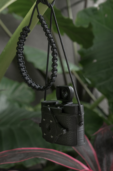
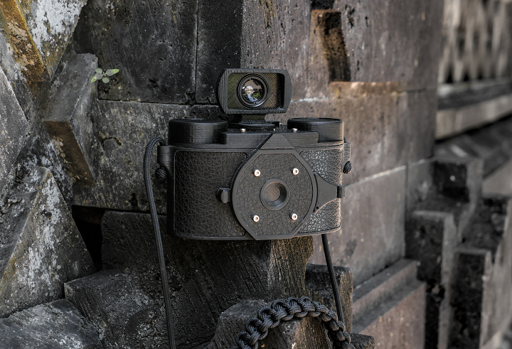
Now, Goodman is introducing her newest exciting 3D printable masterpiece. SCURA, which she tells us is a “love project” of hers, is a 35 mm panoramic pinhole camera that shoots 60 x 25 images.
SCURA
“The system is the same as always, we offer the files free of charge for anyone, all of them are open source,” Goodman told 3DPrint.com.
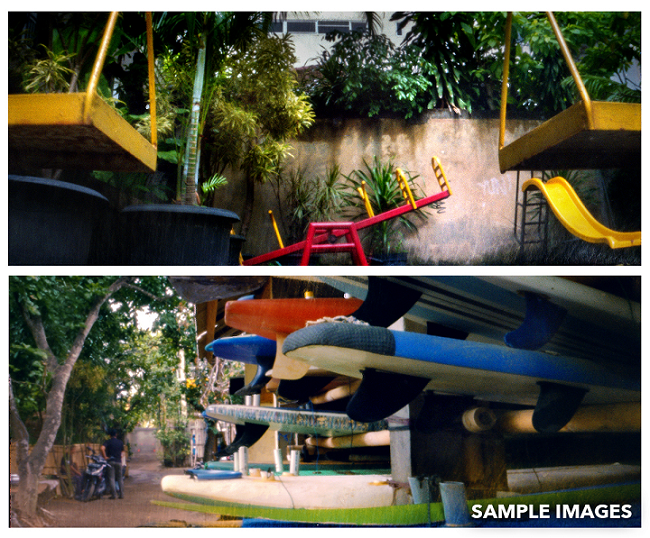
With most pinhole cameras, 3D printed or otherwise, the film lies completely flat inside, which gives the photographs a distorted edge. But the SCURA isn’t most pinhole cameras – it features a special curved design, which allows light to reach all of the film evenly for distortion-free images. The framing was also increased to give the camera a panoramic field of view. Additionally, the most important part of a pinhole camera is the hole, and Goodman “put a lot of effort into finding the technology for the perfect, precisely drilled hole.”
“When working on this camera, we have focused on combining the design and functionality of 3D printing, resulting in a minimalist approach to pinhole photography,” the website states. “Along the laser-drilled pinhole and the curved design, we have managed to achieve a distortion-free, yet amazing picture quality.”
Goodman offers users precise but smooth exposure control with a magnetic shutter, and the SCURA is convenient, as pinhole cameras have only a few simple moving parts. It’s also easy to use, which makes it a good choice for beginner and professional photographers, and because it’s an open source design, the camera is available for anyone to make.
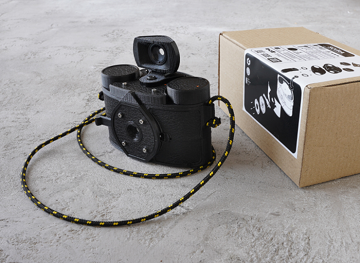
The SCURA is customizable with a self-adhesive stock skin, which comes with the kit, or you can use Goodman’s cut-out sheets and tutorial videos to personalize the camera with your own ideas.
“I always encourage everyone to print their own pinhole camera, to challenge themselves and share their results with us, all our projects are inspired by the different approaches of our community,” Goodman writes.
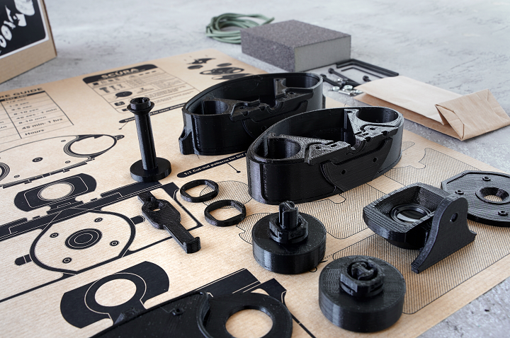
There are two options to get your own SCURA, and the first is to 3D print your own by signing in on the website to gain free access to all of the camera plans and design files. The accessible open source package includes all of the documentation you need to build the SCURA from scratch, which Goodman notes is a “fun and easy” project. But, while the available online guides make assembly fairly straightforward, the process was “designed to be an intriguing journey on the way.”
If you are 3D printing the SCURA yourself, but need the drilled 0.3 mm pinhole plate, shutter magnets, and the screws and key sets for assembly, you can purchase a hardware kit for just $38, which includes an Allen key set, socket head Allen screws, and a male female thread adapter.
But, if you don’t have easy access to a 3D printer, you can also purchase the DIY kit for the SCURA, which includes all of the elements, equipment, and tools you’ll need without having to purchase additional parts. Every part of the pinhole camera in the kit is pre-printed, and you also get the tools, screws, and hardware to assemble and post-process the camera.
The basic kit also includes:
1 laser drilled pinhole plate
1 set of faux-leather decor foil
1 sanding sponge
1 strap cord
zero waste wrapping paper with cut-out samples
There are some additional add-ons you can purchase with the basic $78 DIY kit, such as a viewfinder for $23, a $35 pre-cut wood inlay, and a pro flash mount with bubble level and smartphone holder, also for $35. You can see the exposure information, dimensions, and additional specs for the SCURA on the website, and check out the tutorial video for help building this lightweight yet powerful camera.
Even with all of the optional extras, the SCURA kit costs less than $200, which is a pretty good deal for this attractive, customizable panoramic pinhole camera.
Discuss this story and other 3D printing topics at 3DPrintBoard.com or share your thoughts in the Facebook comments below.