The University of Pittsburgh has developed a depowdering solution for metal 3D printers that could significantly reduce the cost of 3D printed metal parts. Lead by Professor Albert To, a team of undergraduates has made a gyroscope-based depowdering machine. Professor To is the leader of the AMRL, or ANSYS Additive Manufacturing Research Laboratory, at Pitt and also runs the MOST AM lab, which is a cutting edge lab that develops 3D printing simulation tools. To’s ANSYS AMRL teams decided to attempt a much more hands-on project, however, with this depowdering machine, the Pitt Depowdering Machine.
Why is depowdering important?
Post-processing accounts from anywhere from 30 to 60% of the cost of a metal 3D printed part. Far from a machine driven push-button process metal printing technologies such as Powder Bed Fusion require a high degree of manual labor. Files have to be prepared by hand, support strategies have to be thought up builds have to be nested and material has to be loaded. Once the build is done the parts have to be depowdered. This usually involves a brush and vacuum cleaner. Then parts will also have to be destressed, sawed off, tumbled and may require EDM, CNC, precipitation hardening, shot peening etc. All the while a human operator will be carrying the parts around a factory. The actual 3D printing metal process is still rather artisan even though we’re promising the world that we will make millions of car parts cost-effectively. To bridge this gulf automation will be necessary. Additive Industries is including post-processing steps in the machine others are making lines of machines aimed to reduce the cost. The cool thing about adding automated conveying, destressing, EDM wire, and other systems to an existing line is that these add ons can be used to reduce costs in existing lines and be used with machines from several vendors. All of metal 3D printing’s promises and promise will have to be fulfilled through the nuts and bolts of improving and creating industrial processes. Automated post-processing is a key element of that so Pitt’s machine is very timely to say the least.
Pitt Depowdering Machine
To tells 3DPrint.com,
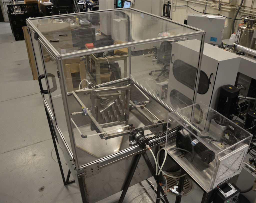
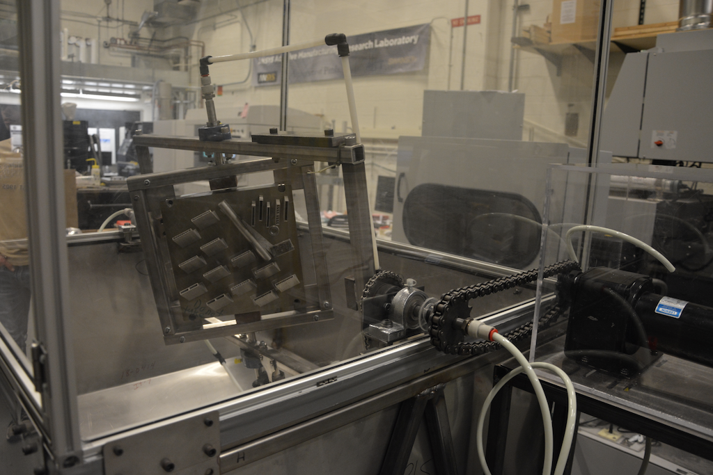
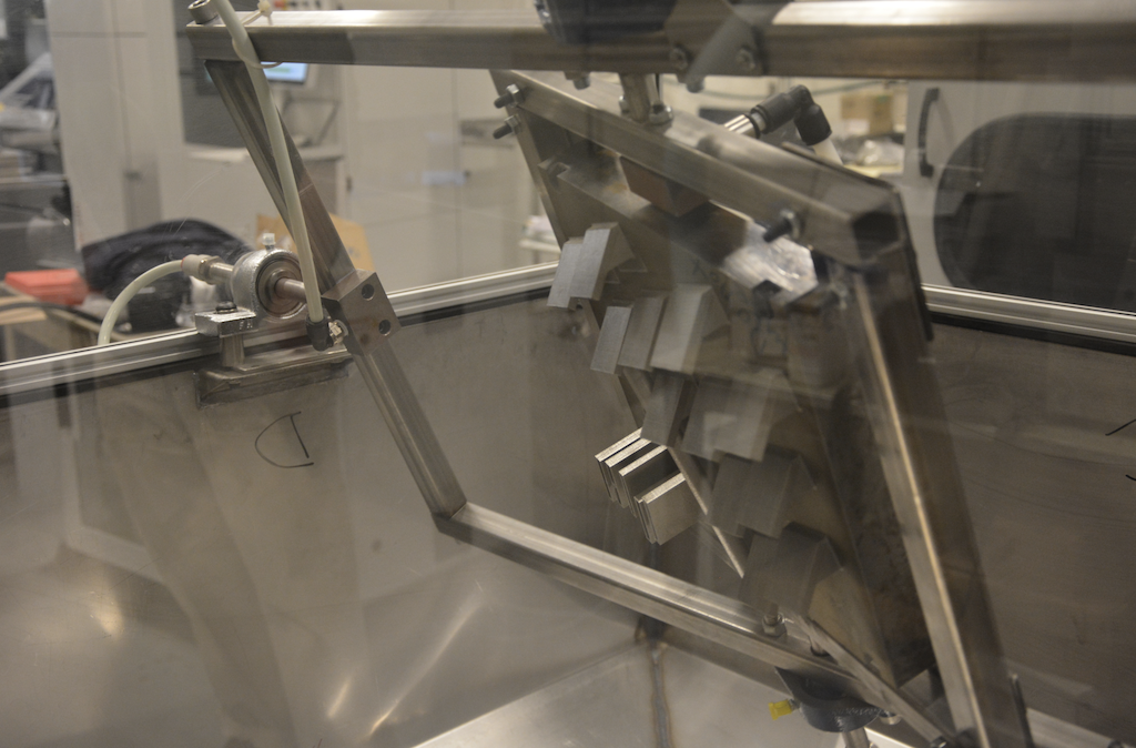
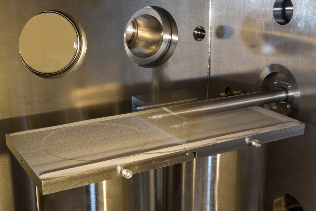
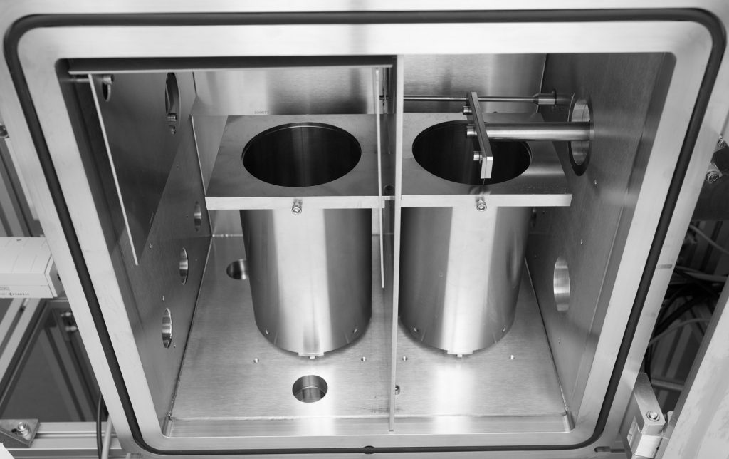
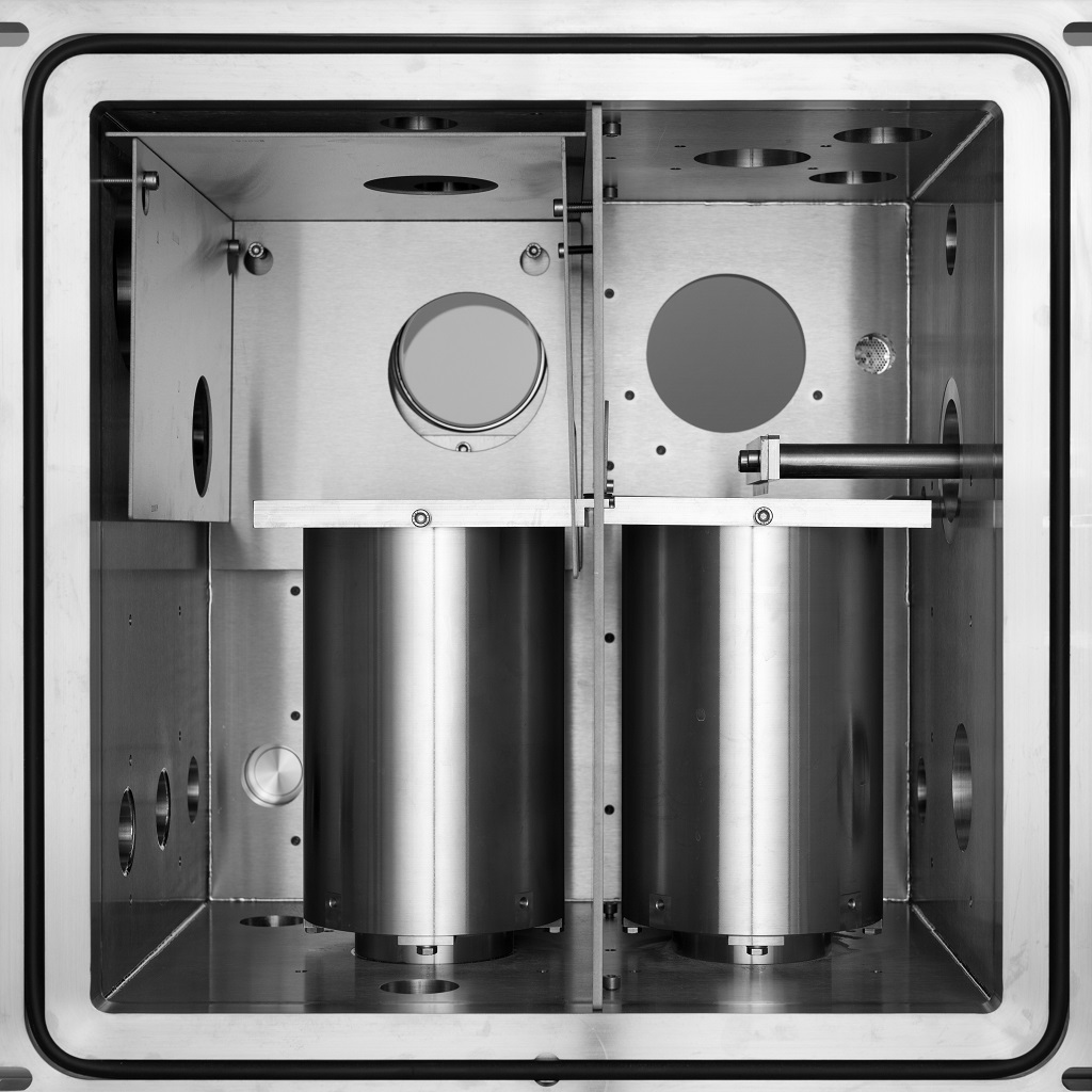
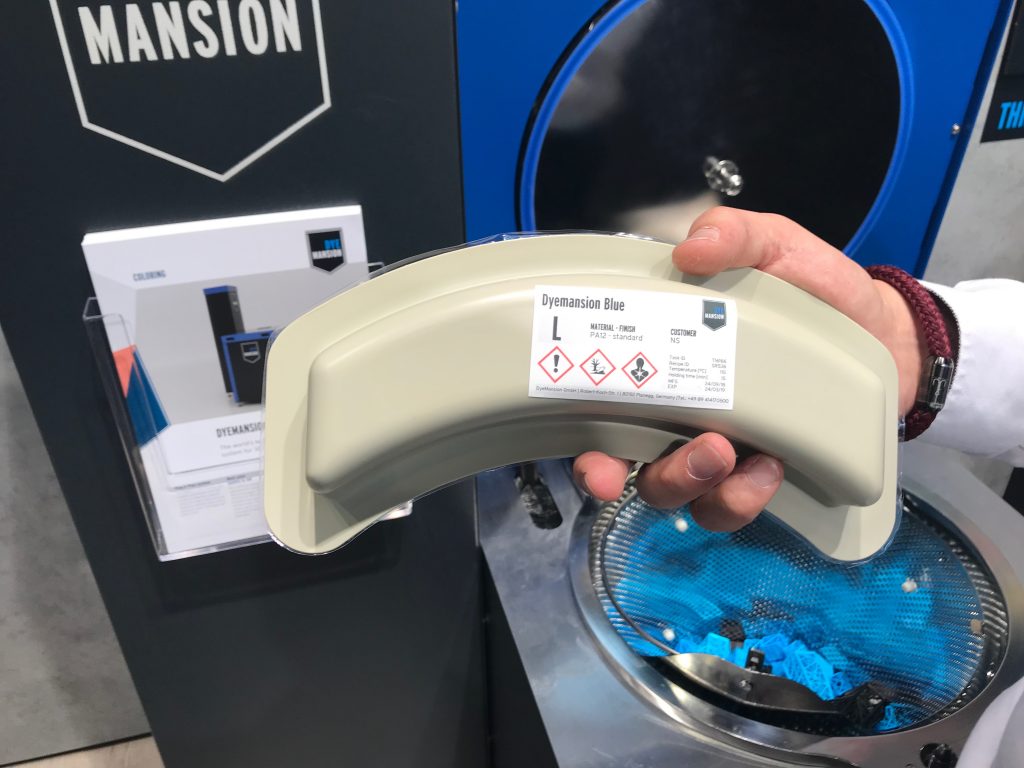
“The depowdering machine employs a gyroscope design that can rotate the AM build 360 degrees in two orthogonal directions. There is a vibrator that is attached to the build and vibrates the build at a high frequency so that the powders are loosened up and come out from the build as the gyroscope is rotating through different angles. There is a funnel below the gyroscope that is used to collect all the powders coming out from the build. The machine is equipped with two sieves at the bottom of the funnel to sieve the powders to the right size for re-use.”
Such a device has the power to reduce a lot of carrying around and operator time. The speed at which one could depowder a build varies enormously but as per the team’s data they should have a huge productivity increase in terms of time over existing users.
“Typically, we put an AM build on the machine for 15-30 minutes depending on the size of the parts,” To said.
That’s not all, however: the machine may also be more efficient than existing processes.
“In one test, the machine shook out 5 more grams of powders after the technician did his best to depowder manually with the aid of a vibrator.”
A vibrator in a metal 3D printing context is a rotary or tub vibrator or a vibratory finisher which is a machine where parts are mixed in with media and then vibrated to de-clog and remove powder.
If the Pitt machine performs like this in continuous operation the savings could be significant.
To says, “We are still evaluating whether to commercialize the machine and talking to other people about it at the moment.”
We would strongly encourage them to commercialize this machine. Any in line device that could really reduce the costs of 3D printed parts would make many more metal 3D printing applications possible.
In ‘Fluid and particle dynamics in laser powder bed fusion,’ authors P. Bidare, I. Bitharas, R.M. Ward, M.M. Attallah, and A.J. Moore examine laser bed and powder bed interaction. In this study, the team was able to study and create images of areas where powder was removed during single line and island scans.
Research gave the scientists further insight into the PBF process, making it obvious that it is more dynamic than previously realized, and includes substantial movement (driven by the laser-induced plume of metal vapor and plasma above the melt pool) between power and agglomerates both in and above the powder bed. Previously, images have been recorded through a Renishaw AM250 3D printer, but laser and powder particles ‘could not be resolved.’ Other image sequences, however, were used to discover powder areas overheating, and then defects.
Schematic of the open-architecture PBF system with modifications for high-speed imaging and schlieren imaging.
The scientists used an open architecture PBF system for in situ measurements, offering automated build of fully dense components. The computer offers:
Vertical movement of the build plate between layers
Movement of the silicon cord powder spreader
Laser illumination and scanning
Flexibility is available for laser power and speed
The system offers high resolution imaging plus the ability to melt single tracks in the powder bed and during builds using multiple layers.
“Minor modifications were made to the top and end faces of the Perspex shielding chamber to incorporate viewing windows,” stated the researchers. “For top views of the powder bed, a window of diameter 50 mm made from infra-red absorbing KG glass was added.”
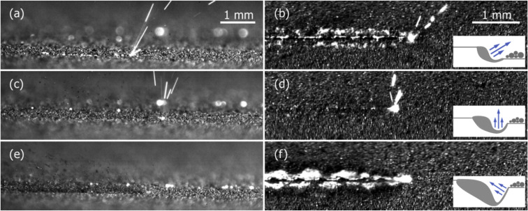
High-speed images for side and top views when scanning single tracks (left to right scan direction) with laser power and scan speeds of (a) and (b) 50 W and 0.1 m/s; (c) and (d) 100 W and 0.5 m/s and (e) and (f) 200 W and 1 m/s. Inset is a schematic of the melt pool shape, which determines the laser plume direction. The videos for all figures are included in the supplementary material.
Direct imaging was allowed through the top viewing window, with an infra-red absorbing window offering the side views. The team inserted the camera onto a tilt stage, transforming the powder bed area, and meaning that several areas could be both scanned and imaged. They then moved forward in imitating gas and plasma dynamics during PBF thermal effects. For process thermodynamics, an energy balance was used to account for all types of heat transfer from conductive to convective to radiative.
Temperature increases build plasma density and powder agglomerates forming when scanning islands.
“Agglomerates can also be affected by the laser plume-induced flow: they can be drawn back into the melted track, presumably with an increased likelihood of producing porosity, or ejected into the atmosphere and produce large molten beads if they interact sufficiently with the laser beam, hot gas, or a combination of both.”
Laser plume was directed in a forward motion for the first time from the melt pool, and other studies have remarked on this happening because of droplet detachment. The team also believes the forward motion is specific to PBF.
“The combined results showed that the inert atmosphere and laser plume are integral to the heat, mass and momentum transfer of the process,” concluded the scientists. “Their inclusion in numerical models is critical to process optimization, to identify parameter sets which result in reduced denudation. Observation of plume and particle behavior under cross-flow emphasized the importance of uniform extraction streams above the bed, carrying enough momentum to prevent contamination of the bed from ejected particles. Taking hydrodynamic phenomena into account during process planning can improve the overall build quality and limit the adverse effects of ejected vapor and particles.”
What do you think of this news? Let us know your thoughts! Join the discussion of this and other 3D printing topics at 3DPrintBoard.com.
(Top) Calculated temperature fields for 50, 100 and 200 W laser power. (Bottom) Calculated velocity surface plot of fast laser plume, with arrows showing the slower atmospheric gas flow that it induces.
In a recently published paper, scientists from Carnegie Mellon University and Argonne National Laboratory used high-speed x-ray imaging to study the keyhole effect in powder-based metal 3D printing. A keyhole is a subcategory of void, or pore, that can sometimes be found in AM components. Anthony Rollett, a co-author of the paper and Professor of […]
Founded in 2012, London-based Betatype works to increase the productivity and efficiency of metal 3D printing, so that it can be used as a viable production technology. The company has worked with the aviation, automotive, and consumer products industries, and is now moving on to the medical field in its latest case study.
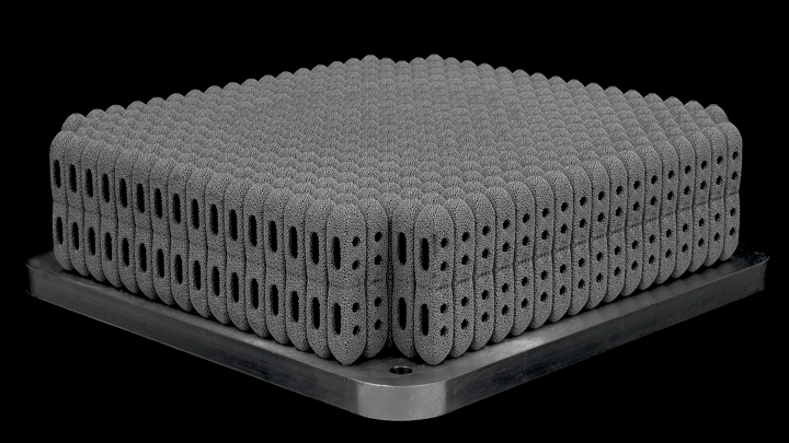
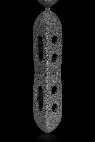
Metal 3D printing, and laser powder bed fusion (PBF) in particular, can be very advantageous when it comes to fabricating orthopaedic implants. Betatype has found time and again that this particular process can majorly increase productivity, as it is able to manufacture strong, complex structures that are durable enough to endure in the human body and can simulate the porous, mesh-like properties of bone, without wasting materials or time. Medical device manufacturers are able to achieve cost-effective serial production of everything from lumbar cages to acetublar cups using PBF, as the technology can be used to make safer, more porous implants of multiple shapes and sizes.
Obviously, orthopaedic implants have a certain level of design complexity, which can result in high volumes of data being generated that then slow down build processors. But Betatype’s innovative data processing platform Engine, which can manage and control multi-scale design, is able to get past this problem thanks to its supercomputing power, and rapidly create scan data for laser PBF 3D printing.
Engine can produce optimized build data, and has what essentially boils down to limitless scalability for generating builds. Recently, Betatype successfully created serial production build data for a company, to the tune of over 50 GB worth of build files. Its Engine platform can scale up to 640 virtual CPUs with 4.88 terabytes of RAM in just a few hours, saving companies time and money.
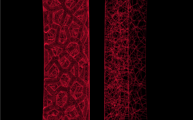
Macro of CAD of spinal cage. L-R: traditional mesh format, and ARCH or LTCX format.
Betatype uses its Engine technology to help its orthopaedic clients achieve lower costs on serial production of implants by lowering process time, optimizing high build data volume, and maximizing machine usage. Engine applies specialist algorithms for converting complex geometry, which lets the implant designers work in file formats, like nTopology’s LTCX data or Betatype’s ARCH format, that are up to 96% more lightweight than STL files; for instance, a spinal cage model that weighed 235 MB as an STL file was only 8MB as an LTCX file.
By combining Engine’s build data generation with these more lightweight representations, Betatype can help designers shorten and simplify the orthopaedic implant manufacturing process, so it’s more cost-effective and flexible, without having to deal with any mesh data.
Single stack of posterior lumbar cages, supported via sacrificial beam elements.
In terms of cost per part for serial production, it’s also very important to properly utilize a 3D printer’s total build volume. Betatype designs lattice node matched supports, which allows it stack implant parts on top of one another – an effective use of build volume that results in the production of many complex implants in one print. In addition, standard media blasting can be used to remove the supports, which is another time-saving feature in that it totally eliminates the need for any kind of manual post processing work.
Betatype’s technology is also able to directly optimize laser firing times, and lower delay times, without having to use multiple lasers. This can decrease build time by as much as 40%, and the more parts you 3D print in a single build, without sacrificing time, the more cost-effective those parts are, which is why equipment amortization can majorly effect the cost of orthopaedic implants 3D printed with laser PBF technology.
It’s possible to break build time down into three separate components, which can be addressed in order to speed up the process:
dosing (applying powder to the machine bed)
fusion (applying energy to the powder bed)
motion (movement between fusion)
In another project, Betatype used its technology portfolio to lower the build time for an orthopaedic manufacturer’s implants to 15.4 hours, down from 25.8 hours. Betatype can optimize its laser scan paths in order to decrease how much movement time and firing is necessary to 3D print complex lattice structures, and galvo-driven path optimization can be used to ensure that only prerequisite delays are applied to the process, lowering delay times from 13 hours to just 3.
Discuss this news and other 3D printing topics at 3DPrintBoard.com or share your thoughts in the Facebook comments below.
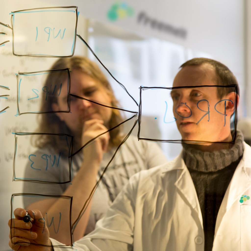
I’ve known Patrik Ohldin for a long time as a supremely knowledgeable metal printing guy. He’s been working in metal 3D printing for over 14 years, 12 of those as an Area Sales Manager for Swedish EBM metal printing company and now GE subsidiary Arcam. He really knows a tonne about EBM and electron beam powder bed fusion technologies. He is also a stand-up guy that knows how to explain, educate and understand business cases in a wide array of areas. Patrik was instrumental in introducing EBM to new areas such as aerospace and orthopedic implants and helped many firms industrialize metal 3D printing. After more than 12 years of selling EBM machines worldwide and being a key player in EBM’s conquest of foreign markets, Patrik co-founded open source electron beam powder bed fusion company Freemelt.
I was flabbergasted. With a war for talent going on for experienced metal 3D printing salespeople (a complex subject that you can’t really learn from a course or book at the moment no matter how much time you have), Patrik didn’t end up joining one of the multi-million dollar VC funded metal printing firms. Experienced metal printing sales are worth their weight in titanium powder (at 2008 prices) and along with application development engineers for powder bed the most sought-after people in 3D printing. I figured he was going to lean back with a big paycheck and equity somewhere. Instead, he wanted to make an open source electron beam powder bed fusion machine. As far as challenges go this was a stupidly complex one to want to undertake. I can not stress enough just how insanely challenging and complicated such a challenge is. Metal printing is a step change more complex than industrial polymer powder bed fusion. The investments, skills, and difficulty would more than eclipse just about any startup out there. Additionally, they were trying to do a 30 million startup on a shoestring. Patrik was a very experienced and very smart man and he surrounded himself with a supremely experienced metal printing team. I was also almost certain that he would fail. Resigned that he would become some kind of quixotic Don Quixote of metal printing I thought I’d at least get a good anecdote out of knowing him. Surprisingly though Freemelt was able to make an open source metal printing platform and what’s more, it started to have traction as well. People kept coming to me saying that they were evaluating their platform and technology. People were excited by Freemelt’s goals to make new alloys for 3D printing possible. Manufacturers liked the fact that there was no lock-in and they had access to all of the technology. Powder metallurgy companies were excited about being able to control and account for all of the variables and use this as a platform to develop materials. The Freemelt ecosystem was growing and the technology was actually viable. Blown away, and sheepishly feeling a bit apologetic, I decided that it was time to interview Patrik about Freemelt.
Freemelt’s Electron Beam Gun.
What is Freemelt?
We provide the world’s first open source electron beam powder bed fusion (E-PBF) metal 3D printer, designed for materials R&D. The metal 3D printing industry’s growth has been tremendous, but its dirty little secret is that only a small number of materials are actually available to use. We are convinced that metal 3D printing’s future lies in (more) materials, and that this is what will drive new applications and sustained growth. But to develop new materials for metal 3D printing as quickly as possible you need many heads and hands with full access to the appropriate tools. We have therefore created Freemelt ONE, an open source development toolbox that gives you complete control of beam paths and hardware, lets you make tests with small amounts of powder, build in vacuum at high process temperatures and attach auxiliary equipment for in-situ process monitoring.
How can I contribute or work with you?
We encourage all types of cooperation since we believe that collaboration is the way forward for metal 3D printing. The most straightforward way to contribute is of course to actually use Freemelt ONE to develop new materials for metal 3D printing. The fact that Freemelt ONE is open source also makes it possible for 3rdparty suppliers of software and hardware to interact with it. Our vision is the creation of a roadmap for metal 3D printing, with well-defined goals and roles that allow the participating companies and institutions to focus on their core competences, thereby moving the whole industry forward.
The powder distribution of the Freemelt One E-PBF 3D printer.
What kind of companies do you wish to work with?
We wish to work with companies and institutions that are interested in developing new powders, new materials and new processing algorithms for metal 3D printing. Universities and research institutes will most likely make up the lion’s share of our customers, but we also see that corporate research centers and powder manufacturers want to use Freemelt ONE to perform their own materials research.
What has changed in 3D printing since you’ve been involved with it?
I would say that the most important change is the industry’s focus on production applications. Major suppliers of CAD software and metal powders have established themselves in metal 3D printing, often via acquisitions. Large industrial corporations develop products to be manufactured with 3D printing and make major investments in their own production capacity. It is also noteworthy that the number of 3rd party suppliers of software and hardware for pre- and post-processing keeps increasing.
What advice would you give to an industrial company that wants to use 3D printing to manufacture?
That it doesn’t make sense to just try to produce existing products with metal 3D printing. The way to go is to use the technology to add product value, for example by redesigning the products to make them easier to produce or to give them increased functionality. The ability to produce parts in new advanced materials, including materials tailored for metal 3D printing with completely new chemical compositions, further increases the likelihood of success.
The Vacuum Chamber of the Freemelt System.
What are the advantages of E-PBF when compared to laser powder bed fusion (L-PBF)?
I would say that E-PBF’s main advantages are the high output power (currently up to 6 kW) that gives high productivity and enables high process temperatures (>1.000 ˚C), and the extremely clean process environment (equivalent to the parts per billion range for oxygen) that the high vacuum provides. Hot processing has proven successful to eliminate internal stresses and deformation of built parts, and also helps prevent crack formation. Furthermore, the electron beam’s high translation speed gives you excellent process temperature control and an unrivaled opportunity to tailor microstructures and material properties. It has for example been demonstrated that single crystal materials can be made with E-PBF. Yet another potential of E-PBF is the multitude of process monitoring technologies that require high vacuum to work. I am convinced that we will see new advanced solutions for E-PBF process monitoring in the future.
Do you see a less expensive generation of E-PBF machines emerging?
As the metal 3D printing industry matures and more companies enter the arena it will undoubtedly lead to increasing price pressure and demand for less expensive machines, both for E-PBF and L-PBF. But ultimately it is the cost and value of the produced parts that drive the decision to invest in and manufacture with metal 3D printing.
Can we do gradient materials with E-PBF? What’s so exciting about that?
Gradient materials are exciting because sometimes it is advantageous to have different material properties in the same part. One such example is turbine blades, where you want different mechanical properties at the root and at the tip. Gradient materials have been attempted with powder bed fusion by gradually mixing different metal powders as the build progresses. Meanwhile, with E-PBF it is possible to obtain gradient material properties with only one metal powder, by using the technology’s precise beam and temperature control to create different microstructures within one single component.
Side view of the Freemelt One vacuum chamber.
What kind of materials are you excited about?
You can use Freemelt ONE’s combination of open source software, high process temperature and high vacuum to develop a wide range of materials for metal 3D printing, for example non-weldable Ni-based superalloys, intermetallics such as titanium aluminide, high-alloyed steels, refractory metals and oxygen-free high-conductivity (OFHC) copper. But at the end of the day, it is our customers who themselves decide which materials to develop with their Freemelt ONE printers.
Recently I’ve seen a lot of excitement about BMG’s (bulk metallic glasses) and intermetallics?
Intermetallics such as titanium aluminides have good material properties in high operating temperatures and weigh only about half as much as superalloys do. They are therefore of great interest to for example manufacturers of aero engines. At the same time intermetallics are challenging since they are generally brittle at room temperature, which makes them difficult and expensive to manufacture with conventional methods. But turbine blades in titanium aluminide are now being manufactured with E-PBF, by taking advantage of the technology’s high process temperature and excellent temperature control. These titanium aluminide turbine blades have already been flight-tested.
BMG’s or amorphous metals are basically alloys with a disordered, non-crystalline microstructure. BMG’s have many interesting applications, but to obtain the glassy state rapid cooling is required in the manufacturing process. L-PBF and E-PBF offer very high cooling rates as compared to traditional manufacturing methods, which is the reason for the recent excitement. BMG manufacturing with E-PBF has indeed been demonstrated. Just keep in mind that the build temperature must be kept well below the “glass transition temperature” to prevent crystallization.
R&D Manager and E-PBF veteran Ulric Ljungblad.
What’s so special about superalloys?
Superalloys retain strength also in very high operating temperatures and are therefore used in, for example, aero engine turbines, where higher temperatures translate to improved fuel efficiency. However, with increasing temperature capability these alloys become more challenging to manufacture as they require high process temperatures and precise temperature control. This makes the E-PBF technology a suitable choice to produce parts in such superalloys.
Two Freemelt Team Members Robin Stephansen Systems Designer (left) and Martin Wildheim Senior Mechanical Designer
What was it like working at Arcam for such a long time?
It was a great experience and a privilege to contribute to the E-PBF journey, and gave us a thorough understanding of the technology’s capabilities and potential. We also took part in successful industrial applications of the technology, such as orthopaedic implants in titanium and turbine blades in titanium aluminide. Going forward, Freemelt’s mission is to continue to develop the E-PBF technology and enable our customers to launch additional successful industrial applications in new materials.
Why is E-PBF such a good technology for space vehicles and rocket engines?
Space vehicles operate under extreme conditions and the space industry, therefore, uses many advanced materials, for example, different high-temperature materials in the rocket engines, and lightweight materials in structural components. There are also many new space companies that manufacture smaller rockets, where the components are small enough to fit nicely inside the build envelope of PBF systems.
Do you see E-PBF being used as the main technology for space vehicles? Or along with L-PBF?
E-PBF and L-PBF are complementary technologies which means that E-PBF will be the technology of choice for some space applications and L-PBF for others. I would say that E-PBF will be used predominantly for high-temperature applications such as rocket engines.
From file to software to machine to finished part takes a design along a path through many different vendors, formats, processes, and interactions. We as an industry are trying to manufacture, reliably with a disparate set of tools and technologies. In between ones and zeroes and finished product we have many crucial steps that get an idea closer towards becoming a thing. Depowdering in powder bed fusion (SLS, selective laser sintering) and other powder technologies such as Multijet Fusion was once seen as a cost center. An annoying laborious task that had to be done. A block of powder with 3D printed parts in it had to be sieved, hand cleaned for the parts to be sorted, matched and shipped. As much as a third of 3D printed part cost is manual labor. You can appreciate this is you see how this depowdering process works and just how labor intensive it is. Companies have traditionally offered tumblers and other surface treatment solutions to ameliorate this and improve surface finish. A few years ago a company wanted to change this. Rather that seeing depowdering as a cost center they saw it as a part of a series of process steps that elevated a mere polymer shape into a consumer-friendly part. Rather than just selling a machine that performed an operation this team, the DyeMansion team developed three different machines that while working together could depowder, surface treat and dye a part. A process chain with a high degree of automation and tooling meant to work together in a highly optimized way. We covered the company before when they raised a series A of five million, when they launched in the US, when they won an award, when they went to AMUG, when they showed at Formnext in 2016 and when they got investment previously.
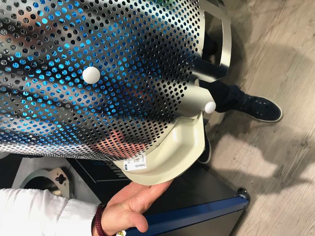
The Powershot C parts cleaning machine, step 1.
When I got started dyeing SLS parts was done in those electric soup kettles that you see at catered events. We used Dylon meant for coloring t-shirts and had a person stirring by hand. Parts would dye unevenly becoming dark blue on one side and lighter on the other. It was a mess always and cauldrons full of red and blue dye were everywhere. It didn’t exactly feel like the future of manufacturing rather more the future of witchcraft. And that is precisely where we are now. We’re going from spells, hope, exotic ingredients and promises to ISO, GMP and repeatable production. What do we see? Everyone wants to make or sell 3D printers, lots of people are developing software and many sell materials but only one firm is developing a line of post-processing solutions that in an integrated way depowders, cleans and surfaces parts. The three machines work in tandem and are rather confusingly named the Dyemansion Powershot C, Powershot S and Dimension DM 60. The Powershot C is not a camera but then again there are precedents in the 3D printing industry in having names similar to camera names. The C cleans parts and depowders them using movement and ionization and damaging parts less than alternatives, while the S is a blasting cabinet with a high degree of automation that gives parts a more closed and more uniform surface texture and structure; and the DM 60 is the dyeing unit.
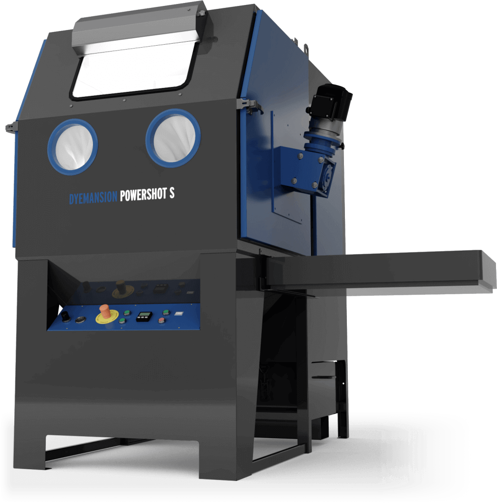
The S, the second step for surfacing.
All in all I’m a huge believer that in a Gold Rush sell picks and shovels and have heard great things about the labor-saving capabilities of these units from friends. We spoke to Kai Witter who after a long 3D printing career became the sales manager at DyeMansion and is helping bring the technology to manufacturers worldwide.
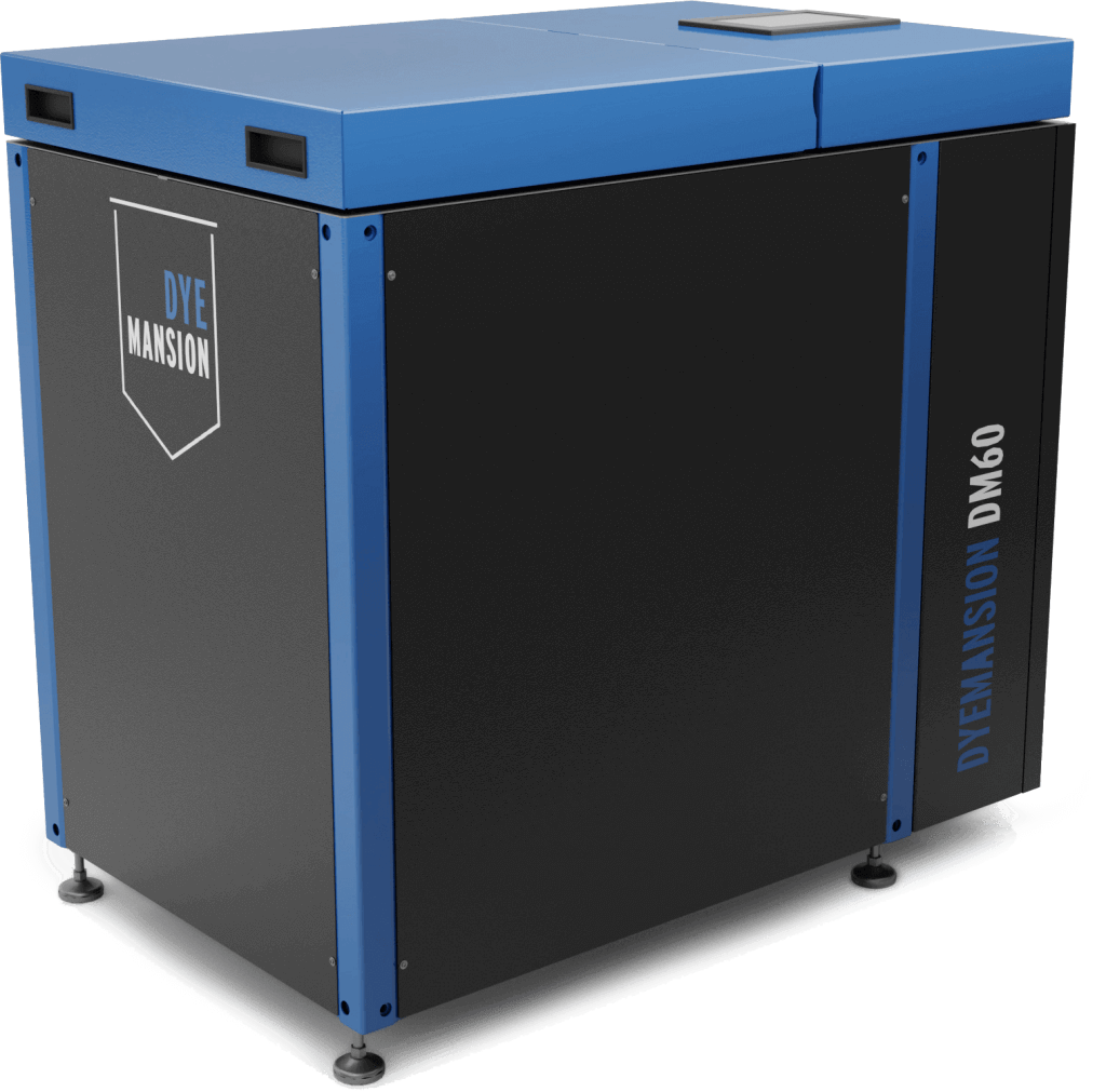
The DM60 Dyeing unit
Kai said that Dyemansion is, “A company that’s evolving from a startup to a global market leader who offers value-adding post-processing solutions for AM plastic parts manufacturing. We are the challenger of the status quo, together with AM printer manufacturers we challenge injection molding industry.”
How much labor does your depowdering station save? If I did 5 full builds a week, how much money or how many hours would I save?
As usual, all this is application dependent. Let’s look at saved hours as cost of conventional manual blasting units and staff costs vary a lot:
The average cleaning time of one batch with PowerShot C is 10 mins
Let’s assume 100 mid-sized mid complex geometry parts (loading volume is a full HP4200 job or 75% of a EOS P3x Job). So we assume 5 Runs/week
Loading and unloading each 2 mins, in total 4 Mins
Powershot C:
4 mins (loading & unloading)
5 runs a week
50 weeks
4 m(ins) x 5 (runs) x 50 (weeks) = 1000 mins or 16,5 hrs
Conventional manual blasting:
3 mins average. cleaning time/part
4 mins (loading & unloading)
5 runs a week
50 weeks
Cleaning: 100 (parts) x 3 (mins) x 5 (runs) x 50 (weeks) = 75.000 mins/1.250hrs
Loading & unloading: 4 (mins) x 5 (runs) x 50 (weeks) = 1.000 mins
76.000 mins or 1267 hrs
16 vs 1267 hrs
Powershot C saves 1251 working hours.
So it is three units that work together? How do they work and how much do they cost?
The three unity combined build an integrated workflow, so called ‘print-2-Product’ workflow to turn 3D printed raw parts into high value products in 3 hours only. Automated, efficient and reproducible.
Powershot C: Cleans parts in 10 mins only, without damaging the surface. Compared to manual cleaning we assure the sensitive surface of 3D printed raw parts is not damaged from too much blasting pressure and broken or worn blasting media.
Powershot S: Refines the surface of the raw parts with a smooth touch, matte-glossy finish and improves scratch and water resistance of the parts in 10 mins only. The PolyShot process prepares the part for homogeneous dye absorption that leads to an even color image over the complete surface of each part and all the parts.
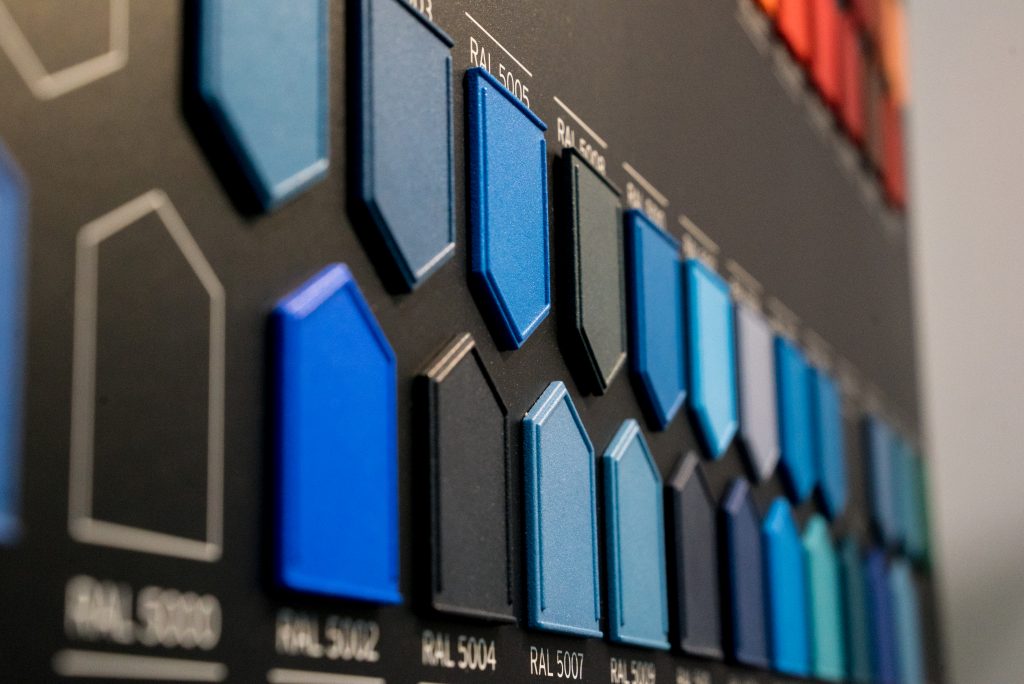
DyeMansion DM60: Is the fully automated Dyeing system to fit out the parts with any color required. The DM60 adds the final value to parts. Launched at tct 2018 we have added 170 standard RAL colors to our out of the box portfolio. Any other color, suiting the material and required finish of the part can be developed at DyeMansion in only 3-4 weeks
So how does it work as an investment?
“If we assume industry standard of 5 years depreciation and the calculation above (saving 1250 hrs pa) customers have a positive impact on their bottom line after the 1st month of using the Powershot C.”
Why is damage prevention so important?
“Our infiltration Dyeing process does not add a layer to the raw part as we know it from spry painting. They dye connects with the material and avoids another process step to create a nice surface. Further it enables to finish printed textures, eg leather structure alike textures as used for automotive or aerospace interior parts.”
What does the ionization do?
“It removes the static charge of the parts and thus avoids that parts attract loose powder residue in the cabin atmosphere back to the parts. It ensures that parts are really clean.”
Why is a homogenous surface quality important?
“A homogeneous dye absorption is the prerequisite for an even color image of the end use part. We finish the printed part including printed textures without any impact on the geometry. Neither the Powershot C (Step 1), nor Powershot S (Step 2) are abrasive and (Step 3) the dyeing, does not add a layer to the part like spray painting does. Thus, an additional process ta accomplish high quality end-use part surface is not required.”
How does the second step work?
“The PolyShot surfacing is a proprietary surface compression process with plastic media to even out the heterogeneous surface roughness and porosity of 3D Printed plastic parts.”
Why is the feel of the product important?
People are used to comparing parts with what they know, such as Injection molded parts. Rough surfaces don’t create an image of quality, they are scratch and dirt sensitive.
It is all about perception and mind change. The high-quality perception of 3D printed parts on a manufacturing level, even if the visual appearance may not be relevant for the functionality (functional end-use parts or functional protoytypes) is a prerequisite to open up more and more applications that are injection molded today, maybe only because of the feel.
Does it make it feel more luxurious?
I would not call it luxurious. I think it meets injection molded standards, at least. Nevertheless, some of our customers from the life style industry describe our matte-glossy look as more valuable than the typical shiny look & feel known from Injection molded parts.
How long do these steps take?
Step 1 – Powershot Cleaning => 10 mins
Step 2 – Polyshot Surfacing => 10 Mins before the dyeing and optionally a few minutes after the dyeing to increase the matte-glossy look & feel.
Step 3 – Dyeing => 90 to 150 mins
How does the coloring process work?
“We have developed an automated, flexible, geometry independent infiltration process where the parts are constantly moving in a water bath. The cartridge is filled with the recipe (reflecting color, material and finish) to accomplish the required color. Further a RFID chip on the cartridge defines the required process parameters such as temperature curve, holding time and pressure that is required. The dye connects with the part as a chemical reaction.
The recipe and DM60 process together make reproducible, high quality end-use parts. The operator just scans the RFID information, adds parts and Cartridge to the part basket of the DM60 and presses start. After 90 – 150 mins the DM60 process is finished including a cleaning and fixation step. When the DM 60 door opens, parts a free of dye.”
How much are the cartridges and how do they work?
“The cartridge price varies between €40 and €105 depending on the required volume of the dyebath.
The cartridge contains the recipe for the required color and the RFID Chip for the required DM60 process parameters. The cartridge is inserted into a shaft at the bottom of the part basket. The cartridge is opened and the dye mixed with the water when the DM60 has reached the process conditions. After 90-150 minutes the parts are ready just a little moisture (Dye free) from the cleaning a fixation phase remains.”
How many colors can I do?
“We have around 200 Colors of the shelf and have developed more than 400 individual colors for customers, such as corporate colors, creative colors and for special finishes. We can develop almost any color within 3-4 weeks development time.The price is €250 for a defined color from a color system such as Pantone and €750 form a reference part.”
What are some of the interesting things customers are doing with your products?
This is always the toughest questions. There are so many interesting and mind-blowing applications with DyeMansion. But the competitive advantage our customers accomplish prevents them from making it public. Famous parts are automotive and Aerospace interior parts, prothesis and orthoses, medical devices and instruments, Eyewear frames and top-notch sports shoes with 3D Printed and DM finished midsoles.
We’re sharing some business news in today’s 3D Printing News Briefs, followed by some interesting research and a cool 3D printed statue. Meld was listed as a finalist in the R&D 100 Awards, and Renishaw has introduced 3D printed versions to its styli range, while there’s an ongoing Digital Construction Grant competition happening in the UK. A researcher from Seoul Tech published a paper about in situ hydrogel in the field of click chemistry, while researchers in Canada focused on the Al10SiMg alloy for their study. Finally, an Arcam technician tested the Q20plus EBM 3D printer by making a unique titanium statue of Thomas Edison.
Meld is R&D 100 Awards Finalist
The global R&D 100 Awards have gone on for 56 years, highlighting the top 100 innovations each year in categories including Process/Prototyping, IT/Electrical, Mechanical Devices/Materials, Analytical/Test, and Software/Services, in addition to Special Recognition Awards for things like Green Tech and Market Disruptor Products. This year, over 50 judges from various industries selected finalists for the awards, one of which is MELD Manufacturing, an already award-winning company with a unique, patented no-melt process for altering, coating, joining, repairing, and 3D printing metal.
“Our mission with MELD is to revolutionize manufacturing and enable the design and manufacture of products not previously possible. MELD is a whole new category of additive manufacturing,” said MELD Manufacturing Corporation CEO Nanci Hardwick. “For example, we’re able to work with unweldable materials, operate our equipment in open-atmosphere, produce much larger parts that other additive processes, and avoid the many issues associated with melt-based technologies.”
The winners will be announced during a ceremony at the Waldorf Astoria in Orlando on November 16th.
Renishaw Introduces 3D Printed Styli
This month, Renishaw introduced a 3D printed stylus version to its already wide range of available styli. The company uses its metal powder bed fusion technology to provide customers with complex, turnkey styli solutions in-house, with the ability to access part features that other styli can’t reach. 3D printing helps to decrease the lead time for custom styli, and can manufacture strong but lightweight titanium styli with complex structures and shapes. Female titanium threads (M2/M3/M4/M5) can be added to fit any additional stylus from Renishaw’s range, and adding a curved 3D printed stylus to its REVO 5-axis inspection system provides flexibility when accessing a component’s critical features. Components with larger features need a larger stylus tip, which Renishaw can now provide in a 3D printed version.
“For precision metrology, there is no substitute for touching the critical features of a component to gather precise surface data,” Renishaw wrote. “Complex parts often demand custom styli to inspect difficult-to-access features. AM styli can access features of parts that other styli cannot reach, providing a flexible, high-performance solution to complex inspection challenges.”
Digital Construction Grant Competition
Recently, a competition opened up in the UK for organizations in need of funding to help increase productivity, performance, and quality in the construction sector. As part of UK Research and Innovation, the organization Innovate UK – a fan of 3D printing – will invest up to £12.5 million on innovative projects meant to help improve and transform construction in the UK. Projects must be led by a for-profit business in the UK, begin this December and end up December of 2020, and address the objectives of the Industrial Strategy Challenge Fund on Transforming Construction. The competition is looking specifically for projects that can improve the construction lifecycle’s three main stages:
Designing and managing buildings through digitally-enabled performance management
Constructing quality buildings using a manufacturing approach
Powering buildings with active energy components and improving build quality
Projects that demonstrate scalable solutions and cross-sector collaboration will be prioritized, and results should lead to a more streamlined process that decreases delays, saves on costs, and improves outputs, productivity, and collaborations. The competition closes at noon on Wednesday, September 19. You can find more information here.
Click Bioprinting Research
Researcher Janarthanan Gopinathan with the Seoul University of Science Technology (Seoul Tech) published a study about click chemistry, which can be used to create multifunctional hydrogel biomaterials for bioprinting ink and tissue engineering applications. These materials can form 3D printable hydrogels that are able to retain live cells, even under a swollen state, without losing their mechanical integrity. In the paper, titled “Click Chemistry-Based Injectable Hydrogels and Bioprinting Inks for Tissue Engineering Applications,” Gopinathan says that regenerative medicine and tissue engineering applications need biomaterials that can be quickly and easily reproduced, are able to generate complex 3D structures that mimic native tissue, and be biodegradable and biocompatible.
“In this review, we present the recent developments of in situ hydrogel in the field of click chemistry reported for the tissue engineering and 3D bioinks applications, by mainly covering the diverse types of click chemistry methods such as Diels–Alder reaction, strain-promoted azide-alkyne cycloaddition reactions, thiol-ene reactions, oxime reactions and other interrelated reactions, excluding enzyme-based reactions,” the paper states.
“Interestingly, the emergence of click chemistry reactions in bioink synthesis for 3D bioprinting have shown the massive potential of these reaction methods in creating 3D tissue constructs. However, the limitations and challenges involved in the click chemistry reactions should be analyzed and bettered to be applied to tissue engineering and 3D bioinks. The future scope of these materials is promising, including their applications in in situ 3D bioprinting for tissue or organ regeneration.”
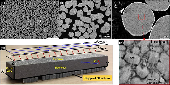
Analysis of Solidification Patterns and Microstructural Developments for Al10SiMg Alloy
a) Secondary SEM surface shot of Al10SiMg powder starting stock, (b) optical micrograph and (c) high-magnification secondary SEM image of the cross-sectional view of the internal microstructure with the corresponding inset shown in (ci); (d) the printed sample and schematic representation of scanning strategy; The bi-directional scan vectors in Layer n+1 are rotated by 67° counter clockwise with respect to those at Layer n.
The paper also characterizes the evolution of the α-Al cellular network, grain structure and texture development, and brought to light many interesting facts, including that the grains’ orientation will align with that of the α-Al cells.
The abstract reads, “A comprehensive analysis of solidification patterns and microstructural development is presented for an Al10SiMg sample produced by Laser Powder Bed Fusion (LPBF). Utilizing a novel scanning strategy that involves counter-clockwise rotation of the scan vector by 67° upon completion of each layer, a relatively randomized cusp-like pattern of protruding/overlapping scan tracks has been produced along the build direction. We show that such a distribution of scan tracks, as well as enhancing densification during LPBF, reduces the overall crystallographic texture in the sample, as opposed to those normally achieved by commonly-used bidirectional or island-based scanning regimes with 90° rotation. It is shown that, under directional solidification conditions present in LPBF, the grain structure is strictly columnar throughout the sample and that the grains’ orientation aligns well with that of the α-Al cells. The size evolution of cells and grains within the melt pools, however, is shown to follow opposite patterns. The cells’/grains’ size distribution and texture in the sample are explained via use of analytical models of cellular solidification as well as the overall heat flow direction and local solidification conditions in relation to the LPBF processing conditions. Such a knowledge of the mechanisms upon which microstructural features evolve throughout a complex solidification process is critical for process optimization and control of mechanical properties in LPBF.”
Co-authors include Hong Qin, Vahid Fallah, Qingshan Dong, Mathieu Brochu, Mark R. Daymond, and Mark Gallerneault.
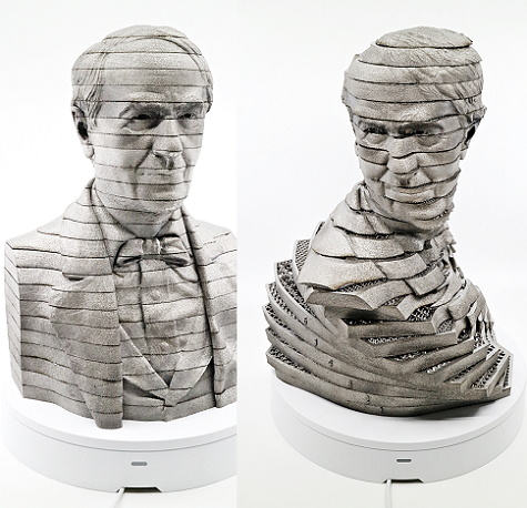
3D Printed Titanium Thomas Edison Statue
Thomas Edison statue, stacked and time lapse build
Oskar Zielinski, a research and development technician at Arcam EBM, a GE Additive company, is responsible for maintaining, repairing, and modifying the company’s electron beam melting (EBM) 3D printers. Zielinski decided that he wanted to test out the Arcam EBM Q20plus 3D printer, but not with just any old benchmark test. Instead, he decided to create and 3D print a titanium (Ti64) statue of Thomas Edison, the founder of GE. He created 25 pieces and different free-floating net structures inside each of the layers, in order to test out the 3D printer’s capabilities. All 4,300 of the statue’s 90-micron layers were 3D printed in one build over a total of 90 hours, with just minimal support between the slices’ outer skins.
The statue stands 387 mm tall, and its interior net structures show off the kind of complicated filigree work that EBM 3D printing is capable of producing. In addition, Zielinski also captured a time lapse, using an Arcam LayerQam, from inside the 3D printer of the statue being printed.
“I am really happy with the result; this final piece is huge,” Zielinski said. “I keep wondering though what Thomas Edison would have thought if someone would have told him during the 19th century about the technology that exists today.”
Discuss these stories and other 3D printing topics at 3DPrintBoard.com or share your thoughts below.