Gradient Temperature Heat Treatment of LPBF 3D-Printed Inconel 718

In order to tailor and improve the performance of microstructures, it helps with many 3D-printed alloys if the post-heat treatment process is carefully designed and executed for this purpose. Researchers Yunhao Zhao, Noah Sargent, Kun Li, and Wei Xiong with the University of Pittsburgh’s Physical Metallurgy and Materials Design Laboratory published a paper, “A new high-throughput method using additive manufacturing for materials design and processing optimization,” about their work on this subject, which was supported by a NASA contract.

They explained that post-heat treatment optimization and composite design are the central parts of materials development, and that “high-throughput (HT) modeling and experimentation are critical to design efficiency.” These aspects are even more important when it comes 3D printing, because the more processing parameters are used, the more the “microstructure-property relationships of the as-fabricated materials” will be effected.

“In this work, we couple the [laser powder bed fusion (LPBF) technique with the gradient temperature heat treatment (GTHT) process as an effective HT tool to accelerate the post-heat treatment design for AM components,” they explained.

They used the Ni-based Inconel 718 superalloy, which has excellent high-temperature mechanical properties, in order to evaluate their proof of concept, as the material is often fabricated with LPBF technology.

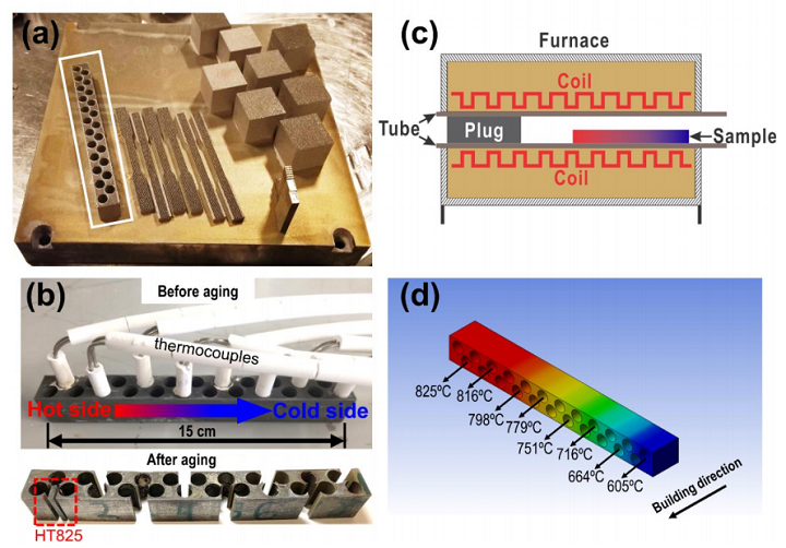
Figure 1. (a) Inconel 718 build printed by LPBF; (b) setup of temperature record and illustration of sample cutting for microstructure characterization; (c) setup of the furnace for the high-throughput experiment; (d) experimental temperature distribution inside the bar-sample.

The researchers created a high-throughput approach by using LPBF technology to print a cuboid long-bar sample out of Inconel 718 on an EOS M290. They designed the build with 23 evenly distributed holes, which not only increase the sample’s surface area and improve convection heat transfer, but also make it more flexible “when choosing monitoring locations.” The improved heat transfer also helped lower the variation in the sample’s temperature relative to the temperature of the air.

“As a result, the air temperature calibration became more representative of the real sample temperature, which allowed the preemptive selection of the monitoring locations in the sample according to the actual needs. Using this methodology, the current work significantly reduced the total time needed for heat treatment, and the flexibility of the setup of the high-throughput experiment was increased by adopting additive manufacturing methods for sample fabrication,” they explained.

Once the long bar sample’s microsegration and AM-related grain texture had been removed, it was submerged in ice water, and then conductive high-temperature cement was used to fix eight K-type thermocouples into equidistant holes. Finally, it was time for the 15-hour aging process of the heat treatment.

“The thermocouples were connected to a computer via a data acquisition system to record the aging temperatures at each location throughout the aging process,” the researchers wrote. “The aging heat treatment was then carried out in a tube furnace with one end open to introduce gradient temperatures at different locations in the sample, as illustrated in Fig. 1(c). The furnace temperature settings and the position of the sample inside of the furnace tube had been deliberately calibrated to acquire a temperature gradient of 600~800°C, within which the δ, γ′, and γ″ phases may precipitate during the aging processes [19]. The temperature gradient during the aging process is stable without fluctuation, and the distribution of temperatures achieved at each monitored location is illustrated in Fig. 1(d). From Fig. 1(d), the experimentally obtained temperature gradient was within 605~825°C, which agreed well with our expectation.”

Figure 2. Temperature diagram of heat treatment with corresponding sample notations.

The adjacent alloy to each thermocouple was individually sectioned to characterize the microstructure, and view the effect of the various aging temperatures. After the samples were polished, they were analyzed with SEM (scanning electron microscope), so the team could identify the phases, and EBSD (electron backscatter diffraction), for grain morphology observation.

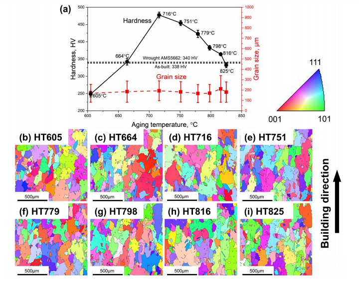
Figure 3. (a) Results of microhardness and average grain size measurements. IPFs of the aged samples with (b) HT605; (c) HT664; (d) HT716; (e) HT751; (f) HT779; (g) HT798; (h) HT816; (i) HT825.

“Within the temperature range of 716~816°C, the hardness of the aged samples are higher than that in the wrought Inconel 718 (340 HV, AMS5662) [14], indicating the AM alloys could achieve higher strengthening effects when applied suitable heat treatment,” they wrote. “The highest hardness is 477.5 HV0.1 and occurs after aging at a temperature of 716°C. It is found that the temperatures above and below 716°C result in the reduction of hardness. The lowest hardness of 248.4 HV0.1 is obtained at 605°C, which is lower than that in the as-built alloy (338 HV0.1).”

The EBSD found that coarse grains formed in all of the aged samples, and while their diameters were “plotted as a function of the corresponding aging temperatures in Fig. 3(a),” their size is independent of the temperature. This likely means that the aging temperatures did not significantly effect either the grain size or morphology, and that “the relatively large grain size achieved after heat treatment in this study has little contribution to the microhardness variation.”

To better understand structure-property relationships, the researchers chose three samples to undergo more microstructure investigation:

  • HT605 with the lowest microhardness of 248.4 HV0.1,
  • HT716 with the highest microhardness of 477.5 HV0.1, and
  • HT825 with the lowest microhardness of 332.2 HV0.1 in the high-temperature gradient

Other than a few NbC carbides, they did not see any other precipitates in the HT605 sample, but noted that 716°C-aging caused a little “of the δ phase to precipitate along grain boundaries” in the HT716 sample.

“However, a large number of plate-shaped γ″ particles are observed in the TEM micrographs,” the team wrote. “These γ″ particles are very fine with a mean particle length of 13.8±4.2 nm through image analysis. The typical γ′ phase with spherical shape is not found to precipitate in sample HT716. This indicates that the precipitation of γ″ preceded the formation of γ′ in the current study. Therefore, the strengthening effect is dominated by γ″ with fine particle size.”

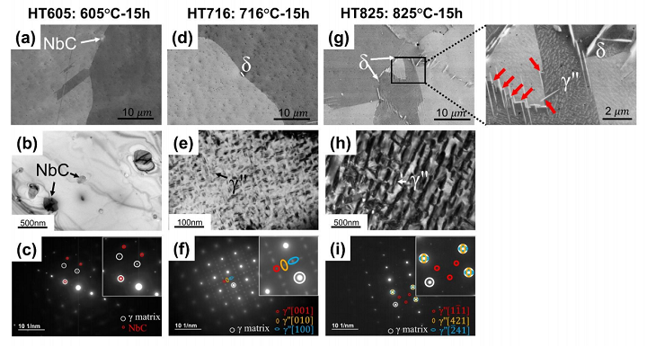
Figure 4. Microstructures of HT605 characterized by (a) SEM-BSE; (b) bright-field TEM; (c) selected-area-electron-diffraction (SAED). Microstructures of HT716 characterized by (d) SEM-BSE; (e) bright-field TEM; (f) SAED. Microstructures of HT825 characterized by (g) SEM-BSE; (h) bright-field TEM; (i) SAED. The different γ″ variants in (f) and (i) are differently colored, and the corresponding zone axes are indicated.

Just like with the second sample, the researchers also did not observe the γ′ phase in HT825.

The team deduced that the phase transformation behaviors caused the varying microhardnesses in the aged samples, concluding that aging the 3D-printed Inconel 718 samples at 605°C for 15 hours is not ideal for precipitation-hardening.

“We developed a high-throughput approach by fabricating a long-bar sample heat-treated under a monitored gradient temperature zone for phase transformation study to accelerate the post-heat treatment design of AM alloys. This approach has been proven efficient to determine the aging temperature with peak hardness. We observed that the precipitation strengthening is predominant for the studied superalloy by laser powder bed fusion, and the grain size variation is insensitive on temperature between 605 and 825ºC.”

Discuss this and other 3D printing topics at 3DPrintBoard.com or share your thoughts below.

The post Gradient Temperature Heat Treatment of LPBF 3D-Printed Inconel 718 appeared first on 3DPrint.com | The Voice of 3D Printing / Additive Manufacturing.

Copper3D Antimicrobial Filament Device Attempts To Reduce HIV Transmission From Breastfeeding

3D printing startup Copper3D, based in Chile and the US, uses nano-copper additives, and adds antimicrobial properties to polymers like PLA and TPU to create antibacterial 3D printed objects. Last year, Copper3D partnered with NASA to study microbial risks in outer space, but now the startup is working on an important project that’s a little closer to home.

According to UNICEF, the number of children and adolescents living with HIV in 2017 reached 3 million, with 430,000 newly infected people and 130,000 deaths from AIDS-related causes. UNAIDS reports that in 2018, 26,000 new HIV infections among children up to the age of 14 resulted from withdrawal of treatment during pregnancy, and breastfeeding. But even with this knowledge, the World Health Organization reports that 37.9 million people around the world were living with HIV at the end of 2018, 8.1 million of which didn’t even know they had the disease to begin with.

Companies and scientists around the globe are working to use technology to help control dangerous bacteria and viruses with high replication rates, like HIV. Copper3D has created a 3D printed device, with its copper nanotechnology, that can effectively inactivate the HIV virus under the right conditions on certain objects- a project that the startup’s Director of Innovation Daniel Martínez tells us is “the result of more than one year of research in antimicrobial polymers and the role on inactivating high replication rate viruses like HIV.”

Dr. Claudia Soto, Copper3D’s Medical Director, said, “Understanding the global problem behind the HIV statistics and analyzing the role that our antimicrobial materials could have in containing the transmission of HIV virus led us think that we could develop some kind of device that acts like an interface between mother and child to prevent the spread of this virus through breastfeeding, which is one of the main routes of infection.

“The initial idea is based on some of the few available studies that establish that copper based additives and filters can inactivate HIV virus in a solution of breastmilk, acting specifically against the protease (essential for viral replication) where copper ions non-specifically degrade the virus phospholipidic plasmatic membrane and denaturalize its nucleic acids; nevertheless, several issues such as toxicity levels, milk nutritional degradation, time for virus inactivation, or the optimal size/form of these filters remain unsolved.”

3D concept of the Viral Inactivator (patent pending)

Copper3D, led by co-founders Martínez, Dr. Soto, and CEO Andrés Acuña, began work on a project with, as the startup stated in a release sent to 3DPrint.com, “two lines of research.” Last year, they submitted a patent application for the project, called Viral Inactivation System for a Breastmilk Shield to Prevent Mother-to-Child Transmission of HIV. First, the viral inactivation effectiveness of its PLACTIVE material was tested with samples of HIV-infected breast milk, and then the team designed an object that optimizes the “viral inactivation of HIV” in the milk, acting as a mother-to-child interface during breastfeeding.

“Our purpose as a company has always been related to make a global impact through innovation in materials and nanotechnology. This line of research of active/antimicrobial medical devices and applications that opens with these studies, fills us with pride as a company. We believe that we are marking a before and after in the industry and we take this honor with a great sense of responsibility,” stated Acuña. “We will continue on the path of applied innovation, always thinking of playing an important role in the most urgent global healthcare challenges, where our antimicrobial materials, intelligent 3D designs, rigorous processes of technical validations and laboratory certifications, can generate a new category of antimicrobial/active devices that can avoid infections at a global scale and save millions of lives.”

Virology Laboratory at Hospital Clínico Universidad de Chile

The startup commissioned a proof-of-concept laboratory study at the Hospital Clínico Universidad de Chile’s Virology Laboratory to validate PLACTIVE’s potential HIV viral inactivation capacity. The study used a split-sample protocol to test and treat 20 sub-samples of HIV-1 (subtype B, cultivated from infectious clone NL4-3, with CXCR4 co- receptor).

The sub-samples were randomized into different groups: A, B, and Control. Samples for A and B were placed in either a green or blue 3D printed box, with and without the nano-copper additive; for a proper blind study, the researchers did not know which was which. The samples were exposed to the medical device for 15, 60, 120, and 900 seconds, and then cultured with HIV-1 Jukat reporter cells LTR-luciferase Cells (1G5); Copper3D performed culture measures on the samples 24, 48, 72, and 96 hours post-treatment.

“The preliminary results showed a reduction of viral replication up to of 58.6% by simply exposition of the samples to the 3D printed boxes containing copper nanoparticles. Fifteen (15) seconds of exposition were enough to achieve such a reduction. These data allow us to infer that by increasing the contact surface by a factor of 10X, we could obtain much higher inactivation rates, very close to 100% (log3) and according to our calculations, most probably in less than 5 seconds,” explained Martínez. “These results are coherent with the hypothesized reduction times proposed by Borkow, et. al. To the best of our knowledge, this is the first essay aiming to study the inactivation of HIV virus by using this new kind of polymers with antimicrobial copper nanotechnology in 3D printed objects.”

3D model of the Viral Inactivator (patent pending)

These results are pretty promising, which bolstered the team as they moved on to the second part of the study – designing a device, with a surface of contact expanded 10X, for HIV-contaminated milk, that’s embedded in nano-copper for use during breastfeeding.

“Like any innovation project, this is a constantly evolving process. We have learned a lot along the way, and we will continue designing, iterating, testing, validating and learning about antimicrobial materials and devices in the future. The preliminary results obtained in the first phase of our investigation with viral inactivation on active/antimicrobial nanocomposites materials gives us a great drive to continue in that line of research,” said Martínez. “We hope in the coming months to conclude the second phase of this study. For these purposes we develop a new antimicrobial flexible TPU based material (MDflex), with the same nanocopper additive as PLACTIVE, to test with new iterations of the design of this viral inactivation device with expanded surfaces of contact that we believe will be much more effective. These new insights will allow the development of a whole new range of active medical devices and applications, with incredible capabilities to interact with the environment, eliminating dangerous bacteria and viruses and protecting patients and users around the globe. This second and final phase of the study will be concluded in Q2 of 2020.”

Copper3D’s concept for its Viral Inactivator is to study how the antimicrobial capacity of its nano-copper materials impacts HIV inactivation, and how different shapes and designs for the 3D printed device can increase the surface of contact with breast milk, while using the nano-copper to enhance effectiveness. The device was made with various layers and “rugosities” in order to imitate what has been observed in the human gastrointestinal tract.

Collaborators at the University of Nebraska at Omaha’s Department of Biomechanics will perform mechanical characterization testing of Copper3D’s prototype.

“Copper3D has once again disrupted the field of medical devices by creating this revolutionary device that can have a tremendous impact in reducing mother-to-child transmission of HIV,” said Jorge Zuniga PhD, Associate Professor of Biomechanics with the university. “Our laboratory is fortuned to partner with Copper3D, in such an impactful project.”

Concept of applications with the Viral Inactivator

Discuss this and other 3D printing topics at 3DPrintBoard.com or share your thoughts below.

The post Copper3D Antimicrobial Filament Device Attempts To Reduce HIV Transmission From Breastfeeding appeared first on 3DPrint.com | The Voice of 3D Printing / Additive Manufacturing.

Teton Simulation’s Software Automatically Finds and Tests Optimal 3D Printing Parameters

In order to achieve successful 3D prints, you need optimal print parameters. Enter slicing software, right? But, most slicers do not have a capability that would make things even easier – physical part simulation, in addition to a recommendation system for choosing those parameters.

US additive manufacturing software startup Teton Simulation, headquartered in Wyoming, is in the latter phases of R&D, and working towards production commercialization, for a really interesting technology called Intelligent Slicing. Teton was one of eight companies selected to present at last year’s RAPID + TCT Innovation Auditions, and is planning to officially announce its technology at this year’s AMUG Conference in March.

Doug Kenik

“The job of a slicer is simple: convert part geometry to instructions for 3d printers. Modern slicers do a great job of accomplishing this while providing the user with near complete control over how a part is printed,” Teton’s VP of Product Doug Kenik told 3DPrint.com. “However, while offering up these controls, slicers fail to provide any guidance into how these controls should be configured in order produce a part that must meet real-life performance requirements. This forces people into the tedious and time-consuming cycle of printing parts, testing them, then adjusting the print profile until they stumble upon a part that meets the requirements. At this point, they have a part that works, but have wasted countless days or weeks of productivity, machine time, and material.”

Physics-based Intelligent Slicing can be easily embedded into existing slicer programs. But, what exactly does Intelligent Slicing do?

“Our technology addresses the gap in the design cycle by guiding the user as to which print parameters to use in order to meet performance requirements while minimizing print time and material usage,” Kenik continued. “The first integration of our technology will be with Cura, which is a great starting point since they are one of the world’s most popular slicers for FFF parts. As a user, all you have to do is define end-use requirements, and then our optimizations routines churn in the background and deliver a list of optimized print profiles that the user can choose from. Since our technology runs in the cloud, we are able to run many parallels simulations which result in blazing fast solution times. At the end of the day, our objective is to save the user time by eliminating print iterations, increase productivity and machine throughput, and reduce material waste.”

According to the Teton website, its proprietary software technology can help users quickly achieve “automatic validation and optimization” of parameters so that parts meet the necessary manufacturing and performance requirements.

“We are currently commercializing technology that will optimize FFF/FDM part print parameters for manufacturing and performance requirements while minimizing print time, with the aim to reduce manufacturing cycles by an order of magnitude,” Rick Dalgarno, the Director of Alliances and Operations at Teton, told us. “Our technology is being integrated into commercial slicing products with the intent of embedding “intelligence” into slicers that is simple to use and fast.”

Rick Dalgarno

Dalgarno tells us that Intelligent Slicing automatically selects 3D printing parameters for optimal structural performance of parts.

A common way to determine the best print parameters is what Teton refers to in a blog post as the “build/break cycle.” If a 3D printed part breaks during testing, you can go back, change some of the parameters, and try it again until you finally have a part that doesn’t break, meaning you’ve landed on a valid set of parameters. Obviously, 3D printing does speed up this process, but it still takes time.

Slicing software is, according to Teton, “entirely disconnected from the initial design requirements,” and also requires a “staggering” amount of print parameters, which are unfortunately necessary as they are responsible for influencing how the part will actually perform in the real world. And while simulation software can help predict how a part will perform without the need for a physical model, a lot of these solutions require a decent amount of prior knowledge. Additionally, even if the software can portray a part’s internal structures, the accuracy of the model is not always perfect.

Teton’s Intelligent Slicing technology can not only optimize and validate print parameters, but also predict their impact on a 3D printed part’s performance. The software offers an intuitive, repeatable, and simple process to slice parts and help lower print iterations.

“Our intent is to remove the ambiguity and confusion of defining slicing parameters by automating the process and identifying the best potential paths the user can take to make a superior part, faster – a process we refer to as Intelligent Slicing,” the website states.

The company provides a good example of how to use its physics-based simulation tool with a bicycle pedal fixture that needs to be optimized for 3D printing.

The simulation tool is embedded in the slicer in order to optimize print parameters and validate the part’s structural performance.

“Let’s focus on infill density for the moment. Imagine that a part is required to have a factor of safety equal to 2. We can think of this as requiring the part to be twice as strong as it needs to be in operation,” the Teton blog states. “What infill density should we use to obtain the desired part strength?

“Suppose that we would like to see if an infill density of 20% would suffice. This value would result in relatively faster print times and lower material usage, but that’s useless if the part doesn’t perform.”

The Intelligent Slicing solution allows users to leverage simulation in the slicer itself to virtually test the part before ever pushing “Start Print Job.” If you receive negative results, no problem – just change the infill density until you find one that works.

Model of the pedal fixture in the Cura slicer

Teton software’s optimization capabilities are great, because Intelligent Slicing can easily tweak multiple possibilities, like layer height and width, the number of walls, and how many top or bottom layers a print might need. Just add the part’s requirements and with the simple press of a button, the software will “intelligently” search all the possibilities until it’s landed on valid parameters.

“Let’s consider this approach for the pedal fixture,” the blog continues. “After setting the requirement for a factor of safety to 2 and specifying how the part will be loaded and anchored, Teton’s software can be used to validate a user-defined set of print parameters or search for optimal choices for valid print parameters. As before, we focus on changing only the infill of the model, but this time, we give the task to the optimization software. In addition to tuning the infill density, our software will also test local variations in infill density using modifier meshes. Such spatially-varying infill properties can be used to great effect for structural performance, as they allow us to target inherently weaker areas of the part.”

Sliced, optimized part: The modifier mesh is in the middle, surrounded by its own walls, which contribute to part strength.

For increased strength, Intelligent Slicing also added a modifier mesh to the middle of the pedal. This helped achieve a set of parameters that resulted in “significantly less time and material usage” than changing up the global infill density would have.

The infill density inside the modifier mesh (45%) is noticeably higher than in the rest of the part (20%); a result of the localization of material to improve structural performance.

“Most of the structural simulation tools on the market are “analyst-level” tools, and we recognized that most people simply don’t have the education or training to feel comfortable in analyst-level workflows. In order to serve a broader market, we decided to develop a tool that could be used by anyone. This means that we had to figure out a way to automate all of the tasks that would typically require an analyst skill set,” Kenik told us about Teton’s target audience. “The end results is a highly automated workflow that is so easy to use, new users can be up and running in literally minutes. A lot of sophistication goes into making engineering software simple but we are very pleased with how we have been able to create an optimization tool that is highly accessible.”

I’ll be curious to hear the reviews of Intelligent Slicing, and see if Teton’s software is as good as it sounds.

Discuss this and other 3D printing topics at 3DPrintBoard.com or share your thoughts below.

[Images: Teton Simulation unless otherwise noted]

The post Teton Simulation’s Software Automatically Finds and Tests Optimal 3D Printing Parameters appeared first on 3DPrint.com | The Voice of 3D Printing / Additive Manufacturing.

Brazil: 3D Printed Miniaturized Platform with Disposable Detector

Brazilian researchers from Instituto de Química explore miniaturized devices in the recently published ‘Design of novel, simple, and inexpensive 3D printing-based miniaturized electrochemical platform containing embedded disposable detector for analytical applications.’

While there are many different methods used today for detection in miniaturized devices, electrochemical methods are attractive to users for the following reasons:

  • Sensitivity
  • Simplicity
  • Ease in operation
  • Potential for miniaturization of instrumentation
  • Low environmental impact
  • Minimal power requirements

Steps for the fabrication of the electro-chemical platform: (A) CAD design of the 3D printed mold used for prototyping the PDMS devices. The internal relief structures were20 mm length × 600 μmwidth × 1 mm height; (B)PDMS device obtained using the 3D printed mold;(C) PDMS miniaturized cell with the integrated working,pseudo-reference and counter electrodes; (D) geometric area of the electrodes delimited with adhesive tape, and (E)electrochemical platform

These techniques are applicable to other applications too, like electrochemical sensors:

“These aspects make the electrochemical techniques affordable, very attractive, and a powerful tool for analytical sciences,” stated the researchers.

Here, pencil graphite was chosen as it is a good alternative to carbon, accessible and affordable, and effective. For this project, the researchers presented a platform with a ‘fully integrated electrochemical detector, fabricated via FDM 3D printing.’

SEM images of the pencil graphite lead surface obtained in different magnifications

For the proof of concept, the device created here was used in analyzing both dopamine DOPA and acetaminophen (AC). This allowed the researchers to evaluate the functionality of the device, as they assessed parameters. Urine sample results were found to be ‘quite satisfactory,’ with the device functioning via a structure containing microchannels with the pencil graphite leads inserted into them, resulting in working electrodes.

“This way, the results reported here testify the good analytical efficiency, precision, and stability of the proposed device, and enables its use for routine analytical procedures and determination of electroactive substances in real samples, even using simple and inexpensive materials. Moreover, the 3D printing-based fabrication protocol used here may be an interesting alternative to the most widely used soft lithography on the fabrication of PDMS-based structures,” concluded the research team.

“It is interesting since the configuration of the devices is easily adjusted and the molds might be fabricated in-house without the use of complex instrumentation and expensive facilities such as clean rooms. Moreover, the device presented here might be used as a detector in other analytical systems such as flow and microfluidic devices. It opens promising new possibilities for application of the approach described here.”

3D printing and miniaturization often accompany each other today, and especially as researchers around the world seek greater opportunity to innovate and push the limits for versatility in a multitude of different applications, using a variety of hardware, software, and materials. As the lab-on-a-chip concept becomes increasingly more popular for scientists and industrial users, other vehicles such as microfluidics and micro-mixers are becoming widely used, along with so many other new methods and materials.

What do you think of this news? Let us know your thoughts! Join the discussion of this and other 3D printing topics at 3DPrintBoard.com.

[Source / Images: ‘Design of novel, simple, and inexpensive 3D printing-based miniaturized electrochemical platform containing embedded disposable detector for analytical applications’]

The post Brazil: 3D Printed Miniaturized Platform with Disposable Detector appeared first on 3DPrint.com | The Voice of 3D Printing / Additive Manufacturing.

Tel Aviv University: Researchers 3D Print Cardiac Patches & Cellularized Hearts

Researchers at Tel Aviv University continue to try to meet the ongoing challenges in cardiac tissue engineering. In ‘3D Printing of Personalized Thick and Perfusable Cardiac Patches and Hearts,’ authors Nadav Noor, Assaf Shapira, Reuven Edri, Idan Gal, Lior Wertheim, and Tal Dvir outline the steps they took to match technology with tissue.

Cardiovascular disease is the leading killer of patients in the US, and organ donor and transplantation processes can still mean a long wait for those suffering from heart failure. Here, the authors demonstrate the need for alternative ways to treat the infarcted (usually referring to clogging of one of more arteries) heart. And while tissue engineering has pointed the way to freeing many patients from terrible physical suffering and organ donor waiting lists, creating the necessary scaffolds with true biocompatibility has presented obstacles.

The authors have created an engineered cardiac patch meant to be transplanted directly onto the patient’s heart, integrating into the ‘host,’ with excess biomaterials degrading over time. This leaves the cardiac patch, full of live, healthy tissue, regenerating a previously defective heart. Because there is always the threat of rejection when implanting anything into the body though, the authors emphasize the need for appropriate materials:

“Most ideally, the biomaterial should possess biochemical, mechanical, and topographical properties similar to those of native tissues,” state the researchers. “Decellularized tissue‐based scaffolds from different sources meet most of these requirements. However, to ensure minimal response of the immune system, completely autologous materials are preferred.”

The researchers were able to create patient-specific cardiac patches in their recent study, extracting fatty tissue from cardiac patients—and then separating cellular and a-cellular materials.

“While the cells were reprogrammed to become pluripotent stem cells, the extra‐cellular matrix (ECM) was processed into a personalized hydrogel,” stated the researchers.  “Following mixture of the cells and the hydrogel, the cells were efficiently differentiated to cardiac cells to create patient‐specific, immunocompatible cardiac patches.”

In using the patient-specific hydrogel as bioink, the researchers were able to create patches, but ultimately, they were also able to 3D print comprehensive tissue structures that include whole hearts.

An omentum tissue is extracted from the patient and while the cells are separated from the matrix, the latter is processed into a personalized thermoresponsive hydrogel. The cells are reprogrammed to become pluripotent and are then differentiated to cardiomyocytes and endothelial cells, followed by encapsulation within the hydrogel to generate the bioinks used for printing. The bioinks are then printed to engineer vascularized patches and complex cellularized structures. The resulting autologous engineered tissue can be transplanted back into the patient, to repair or replace injured/diseased organs with low risk of rejection.

The authors used two different models in their study, with one serving as proof-of-concept, with pluripotent stem cells (iPSCs)‐derived cardiomyocytes (CMs) and endothelial cells (ECs). The other model relied on:

  • Rat neonatal CMs
  • Human umbilical vein endothelial cells (HUVECs)
  • Lumen‐supporting fibroblasts

One bioink, laden with cardiac cells, printed parenchymal tissue, while the other extruded cells for forming blood vessels. The researchers were successful in 3D printing the patient-specific cardiac patches but found when a higher degree of complexity was necessary for fabrication of organs or other tissues, the hydrogels were not strong enough. They created a new process for organs and more complex tissues where they could print in a free-form manner and cure structures at varying temperatures; they were able to overcome previous challenges and 3D print accurate, personalized structures.

Bioinks characterization. A human omentum a) before and b) after decellularization. c) A personalized hydrogel at room temperature (left) and after gelation at 37 °C (right). d) A SEM image of the personalized hydrogel ultrastructural morphology, and e) a histogram of the fibers diameter. f) Rheology measurements of 1% w/v and 2.5% w/v omentum hydrogels, showing the gelation process upon incubation at 37 °C. g) Stromal cells originated from human omental tissues were reprogrammed to become pluripotent stem cells (red: OCT4, green: Ki67 and blue: nuclei). h) Differentiation to ECs as determined by CD31 (green) and vimentin staining (red). Differentiation to cardiac lineage: i) staining for sarcomeric actinin (red), j) staining for NKX2‐5 (red), and TNNT2 (green). Scale bars: (e) = 10 µm, (g,i,j) = 50 µm, (h) = 25 µm.

This study carries substantial weight, considering the researchers were able to create cellularized hearts with ‘natural architectures.’ This furthers the potential for cardiac transplants after heart failure, along with encouraging the process for drug screening. The authors point out that more long-terms studies and research with animal models are necessary.

“Although 3D printing is considered a promising approach for engineering whole organs, several challenges still remain,” conclude the researchers. “These include efficient expansion of iPSCs to obtain the high cell number required for engineering a large, functioning organ. Additionally, new bioengineering approaches are needed to provide long‐term cultivation of the organs and efficient mass transfer, while supplying biochemical and physical cues for maturation.”

“The printed blood vessel network demonstrated in this study is still limited. To address this challenge, strategies to image the entire blood vessels of the heart and to incorporate them in the blueprint of the organ are required. Finally, advanced technologies to precisely print these small‐diameter blood vessels within thick structures should be developed.”

Imaging of the heart and patch modeling. CT image of a) a human heart and b) left ventricle coronary arteries. c) A model of oxygen concentration profile in an engineered patch. d) Replanning of the model showed better oxygen diffusion, sufficient to support cell viability.

Without good heart health, it is very difficult to survive. Responsible for transporting nutrients, oxygen, and more to cells populating the human body, the heart also removes waste like carbon dioxide and more. 3D printing is assisting scientists and doctors in researching and treating a variety of different diseases and conditions, whether they are using 3D printed metamaterials for fabricating heart valves, creating better cardiac catheters, or experimenting with new types of phantoms.

What do you think of this news? Let us know your thoughts! Join the discussion of this and other 3D printing topics at 3DPrintBoard.com.

Printing thick vascularized tissues. a) A top view of a lumen entrance (CD31; green) in a thick cardiac tissue (actinin; pink). b) A model of a tripod blood vessel within a thick engineered cardiac tissue (coordinates in mm), and c) the corresponding lumens in each indicated section of the printed structure. d) Tissue perfusion visualized from dual viewpoints. e–k) A printed small‐scaled, cellularized, human heart. e) The human heart CAD model. f,g) A printed heart within a support bath. h) After extraction, the left and right ventricles were injected with red and blue dyes, respectively, in order to demonstrate hollow chambers and the septum in‐between them. i) 3D confocal image of the printed heart (CMs in pink, ECs in orange). j,k) Cross‐sections of the heart immunostained against sarcomeric actinin (green). Scale bars: (a,c,h, i,j) = 1 mm, (g) = 0.5 cm, (k) = 50 µm.

[Source / Images: 3D Printing of Personalized Thick and Perfusable Cardiac Patches and Hearts]

EOS North America and Link3D Working on Proof of Concept Trial for 3D Printing Workflow Software

Link3D MES & Additive Manufacturing Workflow Software

Today, New York City-based company Link3D, which uses its additive manufacturing execution workflow software to help customers in the 3D printing industry adopt and scale their strategy for Industry 4.0, announced that it will be joining EOS North America in working on a proof of concept trial. Together, the two will collaborate in an effort to increase the customer experience for clients in the benchmarking phase of production. By internally integrating the Link3D Additive MES solution, EOS North America can offer its clients a better overall AM experience.

We consistently strive to work with cutting edge organizations. This includes material, software and hardware solutions for the additive manufacturing industry,” said Dr. Greg Hayes, Director of Applications, EOS North America. “Link3D is one of our choices for software solutions.”

EOS North America, which is an independent business of EOS GmbH, is a technology leader for high quality industrial 3D printing solutions for both metal and polymer materials. Because the company frequently performs benchmark studies from its Novi, Michigan and Pflugerville, Texas technical facilities for customers, it’s able to learn more about how to effectively and efficiently manage AM workflow processes in a “distributed manufacturing model.”

Link3D is humbled to have its Additive MES solution selected by EOS North America to power its metal benchmarking facilities,” said Shane M. Fox, the CEO of Link3D. “We are excited to help increase EOS North America’s operational efficiencies and have our technology integrated into their ecosystem to enable their customer experience.”

Link3D has had a busy few months – in September alone, the company introduced a new Production Planning System for AM workflows and also announced a partnership with the ACAM Aachen Center for Additive Manufacturing in order increase the adoption of 3D printing across Europe. Now, in light of this new collaboration with EOS North America, it doesn’t seem that the company plans to slow down anytime soon.

Link3D is one of the top AMES & Additive Workflow software solutions for streamlining internal and external AM production for OEMs, and has a variety of levels of automation, configuration, and simulation to introduce the many benefits of 3D printing to its customers, which helps in centralizing the digital manufacturing ecosystem. Its Additive MES solution allows Link3D customers to visualize the entire AM workflow, starting with part design and order submission all the way to part inventory, data analytics, and delivery.

Those who use Link3D’s AM workflow software will be able to see how easy it is for people who submit orders for 3D printed parts to directly communicate with application engineers and technicians in order to finalize things like costs and quotes, production requirements, planning, and scheduling, post-processing and quality inspection, and delivery. In addition, customers who purchase the Link3D MES system can rest easy knowing that EOS North America has time tested its Build Simulation software for quoting and costing

Link3D MES digitally connects two sites, which helps improve customer experience and end-to-end transparency and lowers turnaround times. This fits right in with EOS North America’s “holistic solution” for 3D printing, and will help its customers truly understand the potential 3D printing has for production.

Discuss this story and other 3D printing topics at 3DPrintBoard.com or share your thoughts in the Facebook comments below. 

NTU Singapore Researchers Develop Mobile 3D Printing Concrete Collaborative Robots

There’s been a lot of talk about 3D printing construction robots recently, and while we’ve seen some of these robots receive help with their task from drones, we don’t often see them working together to build structures…until now.

Large-scale 3D printing of objects, like buildings, is possible, but volume constraints and length of time can still be issues. Robot arms can be used to print anywhere within reach of the arms, and there have been some gantry systems that are able to 3D print structures, so long as the structure is smaller than it is, of course.

“The way to avoid constraints like these is to have a robot that can both 3D print things and move around, and once you’ve decided to go that route, there’s no reason not to use multiple robots to speed things along,” wrote Evan Ackerman for IEEE Spectrum.

Recently, a team of roboticists from Nanyang Technological University in Singapore (NTU Singapore) published a paper, titled “Large-scale 3D Printing by a Team of Mobile Robots,” in the Automation in Construction journal. The paper details how the researchers were able to complete the actual 3D printing, using two mobile robots operating simultaneously, of a single-piece concrete structure.

The team believes they are the first to have achieved this.

The abstract reads, “Scalability is a problem common to most existing 3D printing processes, where the size of the design is strictly constrained by the chamber volume of the 3D printer. This issue is more pronounced in the building and construction industry, where it is impractical to have printers that are larger than actual buildings. One workaround consists in printing smaller pieces, which can then be assembled on-site. This workaround generates however additional design and process complexities, as well as creates potential weaknesses at the assembly interfaces. In this paper, we propose a 3D printing system that employs multiple mobile robots printing concurrently a large, single-piece, structure. We present our system in detail, and report simulation and experimental results. To our knowledge, this is the first physical demonstration of large-scale, concurrent, 3D printing of a concrete structure by multiple mobile robots.”

These aren’t drones, but instead robot arms on mobile bases. So while there are still restrictions as to how high they can reach, they are far more flexible in terms of length and width than most other systems. Additionally, since you can bring in several cooperating robots for one big project, they are a more efficient option – one robot can tackle one problem, while a second can take on another task, and so on and so forth. Multiple robots also means that you can make stronger, more complex structures at an increased rate of speed, because, as Ackerman put it, “you don’t run into the problem of trying to bond wet concrete to dry concrete where two parts intersect.”

Because the mobile robot system developed by the NTU Singapore researchers can move around and thus define its own build volume, it can actually build structures that are essentially arbitrary in size without needing to make many system changes. You can see the system in action below:

There are all sorts of applications that a fleet of moving construction robots could work on. But the team is currently looking at one in particular, as they explain in their paper:

“Using a fleet of mobile robots for construction could have an extreme potential in other non-conventional aspects. One such application is to allow automated construction in hard-to-reach, remote areas, such as underground caves, the Moon or Mars, to which it is inconvenient or even impossible to bring other kinds of machine required for existing cementitious material printing methods.”

Currently, this system is still just an early proof of concept, so no cave construction yet. While the two robots in the video did collaborate to 3D print a structure, they’re not yet moving around during printing. Additionally, a camera array guides the robots during construction, and the existing system is not designed to be used outside…kind of a problem when you’re 3D printing a large building.

But fear not! Quang-Cuong Pham, one of the researchers, explained that it took the team several years to reach this point and that the work is not done yet, so these issues can be sorted out. Pham said that the mobile robotic 3D printing system has been “a multidisciplinary effort, combining both robotics and cementitious material formulation.”

When it comes to getting the robots to move during 3D printing, Pham explained that it will require “even higher precision in the localization of the base…to ensure that the layers are appropriately positioned one above the other.”

The team will also be working to add on-board obstacle (and human) detection to improve the autonomy of the robots, in addition to putting the robot arms on scissor lifts to increase their reach.

Co-authors of the paper are Xu Zhang, Mingyang Li, Jian Hui Lim, Yiwei Weng, Yi Wei Daniel Tay, Hung Pham, and Pham, all of whom are with NTU’s Singapore Centre for 3D Printing at the university’s School of Mechanical & Aerospace Engineering.

Discuss this story and other 3D printing topics at 3DPrintBoard.com or share your thoughts in the Facebook comments below.

[Images: Nanyang Technological University]

Thesis Provides Proof of Concept for Using 3D Printing to Improve Design of Internal Pressure Relief Valve

Test pumps installed on 75 HP dynamometer: Test Setup Discharge Port at 90°

Over the years, 3D printing has proven to be a pretty handy technology to have in one’s toolbox when it comes to making replacement and mechanical parts, like hand water pumps, transmissions, gears, and valves. For his Master’s of Science thesis this year, titled “3D printed relief valve analysis and validation,” John Anthony Dutcher, III, a student at the University of Northern Iowa‘s Department of Technology, used SLA 3D printing to fabricate prototypes of the internal pressure relief valve of a positive displacement pump.

The abstract states, “Additive Manufacturing allows for faster, lower cost product development including customization, print at point of use, and low cost per volume produced. This research uses Stereolithography produced prototypes to develop an improvement to an existing product, the internal pressure relief valve of a positive displacement pump. Four 3D printed prototype assemblies were developed and tested in this research. The relief valve assemblies consisted of additive manufacturing produced pressure vessel components, post processed, and installed on the positive displacement pump with no additional machining. Prototype designs were analyzed with Computational Fluid Dynamic simulation to increase flow through the valve. The simulation was validated with performance testing to reduce the cracking to full bypass pressure range of the valve. By reducing this operational range of the valve, the power requirement of the pump drive system could be reduced allowing for increased energy efficiency in pump drive systems. Performance testing of the 3D printed relief valves measured pump flow, poppet movement within the valve, and discharge pressure at operational conditions similar to existing applications. The Stereolithography prototype assemblies performed very well, demonstrating a 56% reduction in the pressure differential of the cracking to full bypass stage of the valve. This research has demonstrated the short term ability of additive manufactured produced components to replace existing metal components in pressure vessel applications.”

The gear found inside positive displacement pumps, developed over a century ago, was able to overcome existing performance limitations, but it was by no means perfect. These pumps need an internal relief valve, which provide protection against too much pressure; if there’s a reduction in discharge flow, the over-pressure system could fail.

“The primary focus of this research is to investigate the performance of an internal relief valve for a positive displacement pump, propose an improvement to flow conditions in the cracking to full bypass pressure range of the valve based on flow simulation and validate the performance improvement with 3D printed prototypes,” Dutcher wrote.

SLA Part Production

Over the years, the design of the internal relief valve in these positive displacements pumps has not changed much. But by using computer simulation, the design can be revised and optimized to make the part more efficient. As he wrote in his paper, Dutcher’s research validates the 3D printed prototypes, using Computational Fluid Dynamics simulation and perfrmance testing, “in the design development of an improvement to an existing product,” and also shows that costs and time can both be reduced by using 3D printing to manufacture the valve.

“Additive manufacturing has the benefit of customization, allowing for design changes,” Dutcher wrote.

“Developing customizable end use components that can manufactured at the point of use, allows for application specific products to be produced for pressure vessel applications.”

The valve prototypes, 3D printed using SLA technology, were shown to reduce the amount of cracking in order to fully bypass the stage differential pressure that’s necessary to operate the internal relief valve. FDM 3D printing was used to make mounting brackets to attach an LVDT sensor to the valve prototypes; this sensor measures the movement of the poppet (internal device in the relief valve that seals its surface) during testing.

Assembled Reference Valve Extended

In his thesis, Dutcher wanted to determine if 3D printing could successfully be used to produce components of a test valve for the positive displacement pump, if the valve’s geometry was able to be optimized to reduce cracking based on flow conditions, and if the 3D printed prototype valves would perform at the same level as existing ones made with conventional methods of manufacturing. Ultimately, while he did answer these questions and demonstrated that 3D printing does indeed have applications in developing new products, his research provided a viable proof of concept for improving the existing design of a product.

“The 3D printed prototypes were developed to reduce cost and delivery lead time for prototype testing,” Dutcher wrote.

“The flexibility in design permutations that additive manufacturing allows with customization provides the opportunity to validate multiple product designs in parallel.”

SLA Support Structures

By using 3D printing to create the prototypes, Dutcher was able to develop several different design concepts at the same time, without getting caught up by the normal barriers that come with traditional manufacturing methods. SLA 3D printing also makes it possible to produce parts with “the dimensional tolerances of machined components,” which helps speed up the development of prototypes.

“This research has demonstrated the SLA 3D printing’s ability to reproduce existing machined metal components,” Dutcher concluded. “While extended performance testing was not the intent of this research, the 3D printed pressure vessel valve components performed very well in performance testing. The development of the design variations in timely manor would not have been possible without Additive Manufacturing. Testing has shown an improvement in the valve performance by reducing the cracking to full bypass pressure from 52.0 psi to 22.8 psi. The successful performance test to improve an existing product demonstrated the validity of the SLA 3D printed prototype assemblies.”

Discuss this research and other 3D printing topics at 3DPrintBoard.com or share your thoughts in the Facebook comments below.