
Researchers Thomas Campbell and James F.X. Jones, both of the School of Medicine, University College Dublin, Ireland, have a created a new 3D printer for the medical field, detailing their work in the recently published ‘Design and implementation of a low cost, modular, adaptable and open-source XYZ positioning system for neurophysiology.’
The authors have created an open-source system that can be customized for a wide range of projects, relying on an XYZ positioning system capable of moving a sensor or probe. Like a gantry crane, this new FDM printer is run by a standard Raspberry Pi 3, Arduino Mega, RAMPS 1.4 motor shield, and NEMA17 bipolar stepper motors. The frame consists of 20×20 mm aluminum extrusion made with 3D printed parts, bolted together by brackets. ‘Entry cost’ for such a 3D printer was calculated at approximately $670.20.
With the integration of the Raspberry Pi 3, the authors were also able to incorporate the Open Computer Vision Library (OpenCV) stating that feature is what makes the system unique in comparison to other XYZ positioning systems. The open-source machine learning software library is used with automated movement, and the creators expect it to transform the exploration of mechanotransduction, the method for sensory neurons to change a mechanical stimulus to an electrical signal.
Movement of the 3D printer is controlled by the Arduino Mega, which in turn is controlled by the Raspberry Pi 3:
“Arranging the microcontrollers in this master-slave configuration permits the automation of complex movement paradigms through the Python3 programming language. The power source for the system depends on the intended use case. For neurophysiology a linear regulated 12 V DC power supply must be used to ensure low EMI how-ever for other applications a 12 V DC switching power supply suffices.”
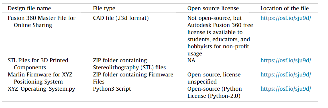
Campbell and Jones chose PLA for the materials to print components, using a Prusa i3 MK3, modeling the calibration cube in Autodesk Fusion360, and stating that dimensions for each cube were measured with digital calipers six times. Supports were not necessary for any of the fabricated parts, all of which were designed with minimal overhang.

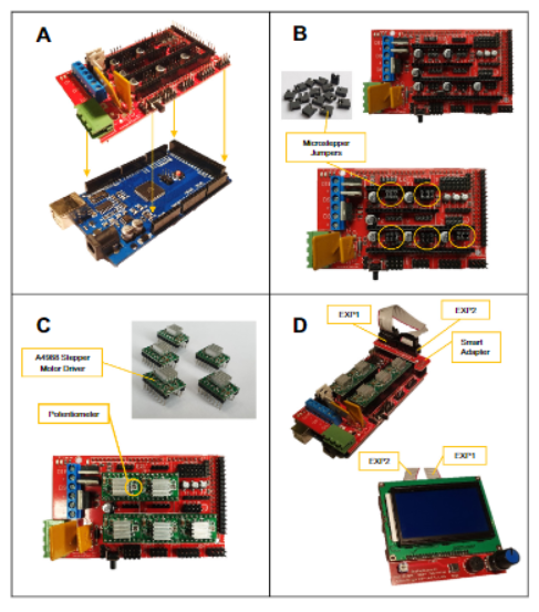
Wiring of XYZ System. (A) RAMPS 1.4 shield (top) and Arduino Mega (bottom). (B) RAMPS 1.4 shield and microstepping jumpers (top). RAMPS 1.4shield with microstepping jumper pins installed (bottom). Note, to enable 1/16 microstepping for each stepper motor, it is necessary to install three jumpers per motor as encircled. (C) A4988 stepper motor drivers shown individually (top) and installed on RAMPS 1.4 shield (bottom). (D) Connecting the LCD screen to the RAMPS 1.4 shield. First, the smart adapter module is seated on the pins at the end of the RAMPS 1.4 shield. Next, EXP1 and EXP2 on the smart module should be connected to their corresponding ports on the reverse of the LCD screen. (E) The Arduino Mega and Raspberry Pi 3 can be connected over USB using a type A male to type B male connector. (F) Wiring of limit switches and stepper motors to RAMPS 1.4 shield. Note both the color orientation for stepper motor wiring and the highlighted pins for limit switch wiring.10T. Campbell, J.F.X. Jones /HardwareX 7 (2020) e00098
Build instructions include:
- Y-axis carriage assembly
- X and Z axes assembly
- Axis alignment
- Electronics and wiring
- Preparation of and uploading of Marlin firmware
- Setup of the Raspberry Pi 3 & OpenCV
- Creation of a terminal based operating system
For use in functional neurophysiology applications, the authors tested the machine to see if it was capable of prompting mechanotransduction within the muscle spindle. Activation thresholds were successfully shown for:
- Stretch distance
- Stretch velocity
- Stretch acceleration
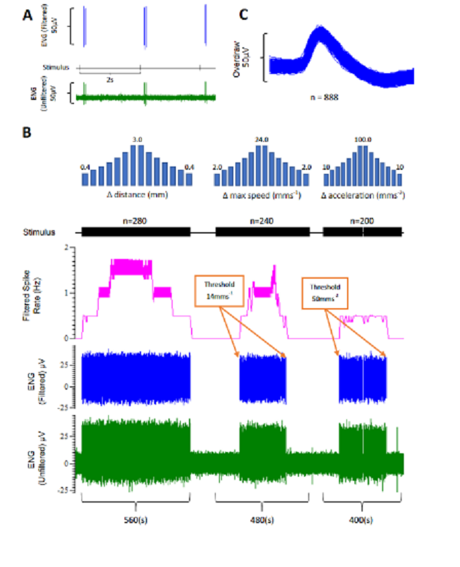
Stretching the muscle spindle to study mechanotransduction. (A) Afferent nerve activity from a stretched muscle spindle. Brief pulses of stretch wereapplied to the lumbrical every two seconds in order to elicit mechanotransduction from the muscle spindle. Each Stimulus pulse indicates the initiation of a stretch. Filtered nerve activity is represented in blue, unfiltered in green. (B) Mechanotransduction activation thresholds were assessed with gradual increments in the stretch distance, speed or acceleration. For this filtered unit, activation thresholds were observed at 14.0 mms x 1and 50 mms x 2. Increased stretch distance, speed or acceleration are associated with increased nerve activity (Filtered Spike Rate). (C) Overdraw of filtered nerve activity observed in(B) indicates that this was a single-unit recording. All data was recorded in Spike2 (Cambridge Electronic Design). ENG, Electroneurogram. (For interpretation of the references to color in this figure legend, the reader is referred to the web version of this article.)18T. Campbell, J.F.X. Jones /HardwareX 7 (2020) e00098.
“The main limitations of the XYZ positioning system are mechanical in nature,” concluded the authors. “In our implementation, the X & Z axis assembly is tall and heavy and as such we opted to reduce the Y and Z axis travel speeds to 2 mms x 1and 5 mms x 1respectively. This reduction in speed preserves positional integrity of the system by reducing the likelihood of stepper motors stepping erroneously. However, the assembly can be adjusted to the desired specific use case and a simple reduction the size of the Z-axis would greatly reduce its inertia and permit positional accuracy at greater travel speeds.”
“All components and software utilized were open-source, free to access or available at low cost. Given the ease with which these components can be accessed and the potential that such a system offers, it is believed that other research groups may find this system an attractive and useful experimental tool.”
3D printers are being used—and created—for many purposes in medical applications like dental, bioprinting, also offering a wide range of tools for doctors and surgeons like medical models and instruments. What do you think of this news? Let us know your thoughts! Join the discussion of this and other 3D printing topics at 3DPrintBoard.com.
[Source / Images: ‘Design and implementation of a low cost, modular, adaptable and open-source XYZ positioning system for neurophysiology’]
The post Ireland: Researchers Create Open-Source 3D Printer for Neurophysiology appeared first on 3DPrint.com | The Voice of 3D Printing / Additive Manufacturing.
