Digital Survey Technology & 3D Printing Used to Create Model of Ancient Mayan Acropolis

Located in the northern Petén Department of Guatemala near the Salsipuedes River, La Blanca is an ancient Mayan settlement, and one of its main archaeological focal points is the Acropolis, which was built as a residence for the city’s rulers during the Late Classical Period (AD 600-850). It consists of three buildings, two with thatched roofs and one with a soil layer, on a platform reached by a large staircase. Research into the settlement has been frequent over the years, which is why in 2010, a Visitor’s Center was built there as part of the La Blanca Project framework. Tourists receive support there, while locals have a good place to participate in cultural heritage workshops and view educational materials.

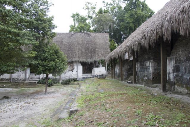
Southeast area of the Acropolis.

One thing it was lacking, however, was a scale replica of the Acropolis to use as a tool for the dissemination of Mayan architectural heritage. This would have been difficult to achieve before digital survey techniques, but 3D technology is changing how we document and preserve cultural heritage sites. A trio of researchers from the Universitat Politècnica de València (UPV) published a case study about using 3D printing for this purpose at La Blanca, and how the team was able to document the complex using digital survey technology “to obtain a high-fidelity model of the Acropolis’ buildings.”

The objectives were to improve the contents of the Visitor Center’s exhibition hall with a model of the Acropolis, perform an in-depth study of “all the procedures used to obtain the Acropolis reality-based model and propose a workflow that could be used in similar cases,” and test these resources for use in dissemination of Mayan history.

The project actually began in 2012 with a Faro Focus3D S120 scanner, which is a fast but compact Terrestrial Laser Scanner (TLS) that can provide efficient 3D measurements. Between 2012 and 2015, three digital survey campaigns were conducted at various parts of the Acropolis, for a total of 118 scans.

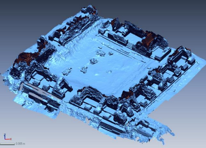
Acquisition Parameters and final Point Cloud Model

“Having acquired these scans, we carried out the point clouds registration in a laboratory and obtained the reality-based Point Cloud Model of the Acropolis,” the researchers stated. “This model showed a very high geometric accuracy and was useful for extracting 2D classic drawings and for obtaining 3D polygonal mesh models.”

It was important to create a methodology for reverse modeling of the Acropolis, which started with the laser scanning data.

“In general, it is possible to print 3D objects starting from a traditional 3D model that has been modeled directly (as in the case of the model of a building we are designing) or from a reality-based 3D model that has been obtained from real data acquired by laser scanning or by digital photogrammetry,” they explained.

Reverse modeling software can create a 3D polygonal mesh from a point cloud model, but the first mesh typically needs to be optimized to achieve a model with high enough quality that it can be 3D printed. Optimizing and building the 3D mesh model of the Acropolis was tough because there was a lot of redundant data from earlier scanning, and the highest parts of the wall lacked data, as “the thatched-roofs system caused occlusion areas,” but they managed.

“First, the 3D point model of the Acropolis was exported into .ptx format in 9 parts. Then, every section of the model was imported into the software 3D System Rapidform with a ¼ factor of reduction. In the same software, we built separately 9 different high-poly meshes,” they wrote. “The heterogeneous structure of the single 9 meshes was an additional problem caused by the higher or lower redundancy of data acquired in different field seasons.”

Reality-based mesh of the Acropolis.

They completed a “global re-meshing” of these nine to reduce the number of polygons in the final model and homogenize the average size of their edges, as well as their number and distribution. Then each mesh was processed separately to fill boundaries and negate topological errors, like overlaying or redundant polygons. Once all the meshes were combined, the team had a medium-poly model of the Acropolis.

They still needed to integrate the 3D model with these procedures, and turned to reverse modeling and other software tools to finish it. They completed a manual retopology of the model’s boundaries, which allowed them to obtain simplified contours; these were then used “as references for the direct modeling of the missing sections of the Acropolis.” They had to then homogenize the structures of both meshes using Luxology Modo and 3D System Rapidform, and then merged the meshes into one model.

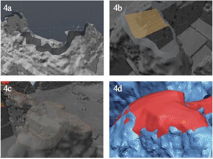
Integration of the model. 4a: Retopology of the boundaries; 4b: Direct modeling; 4c: Resultant mesh; 4d: Smoothing the mesh.

Maxon Cinema 4D’s sculpting tools were used to improve the model’s homogenization, which also “helped emphasize the difference between the reality-based parts of the model and the directly modeled surfaces that had been undetected by the laser scanner.” Finally, the terrain mesh was integrated with the help of a geometric modeling tool, and the 3D model of the Acropolis, “consisting of 6,043,072 polygons with a homogeneous structure over the entire mesh,” was ready to be 3D printed. The team did note a slight mesh deviation between one of the original high-poly meshes and the final model, but the FDM 3D printer they used could handle it.

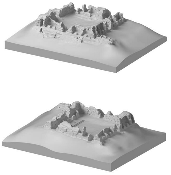
The final Acropolis model.

The team conducted a few print tests with different configurations and scales in order to select the proper settings before printing the entire model out of PLA, the results of which were very accurate when compared with the virtual 3D model.

“The missing parts of the Acropolis, undetected by laser scanner and then manually reconstructed, appeared to be perfectly integrated in the 3D printed version of the model and showed, at the same time, their diversity from the reality-based parts of the model,” the researchers wrote.

“From the analysis of these tests, we concluded that the representation of the Acropolis was satisfactory.”

The last test, with 1:100 scale and 0.3 mm accuracy, offered the best fidelity, so the team printed the Acropolis model with these parameters. It was printed in 17 different parts, as the final measurements of 90 x 70 cm were too large for the print bed; however, this ended up being helpful when it came time to transport the model to La Blanca. It was reassembled there, and sits in the middle of the La Blanca Visitor Center’s exhibition hall, protected by a transparent plastic dome, for all to enjoy.

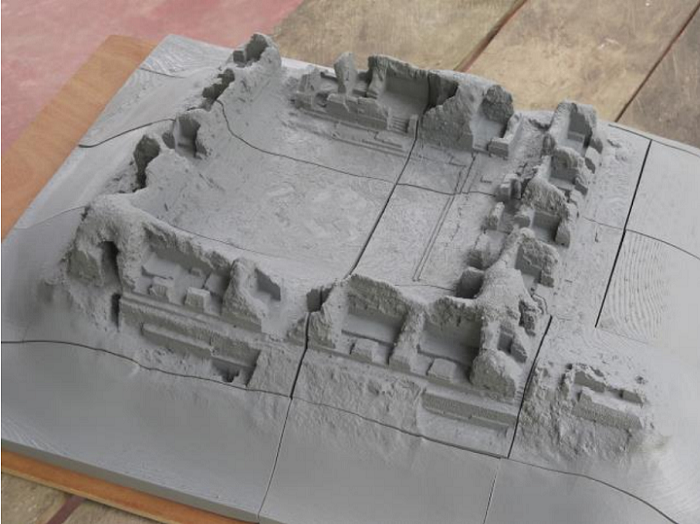
Final 3D printed model of the Acropolis.

“Today, this physical replica of the Acropolis is an important resource that allows the visitors to have a complete view of the main complex of the site, which is not easy in the Guatemalan jungle,” the researchers concluded. “It also provides an exclusive view of some parts of the Acropolis, already studied by researchers and now protected with a soil layer to ensure their preservation. Moreover, it is a useful resource for supporting dissemination and also serves as a teaching resource for student visitors.”

The post Digital Survey Technology & 3D Printing Used to Create Model of Ancient Mayan Acropolis appeared first on 3DPrint.com | The Voice of 3D Printing / Additive Manufacturing.

Michigan Tech Develops Open Source Smart Vision for 3D Printing Quality Control

Monitoring and quality control systems are becoming more widespread in additive manufacturing as a means of ensuring repeatability and aiming for first-time-right parts. A greater need for quality control are now trickling down to items that are more commonly made by the average consumer using FFF 3D printers, as detailed in “Open Source Computer Vision-based Layer-wise 3D Printing Analysis,” by Aliaksei L. Petsiuk and Joshua M. Pearce.

Dr. Joshua Pearce, an associate professor of materials science & engineering, and electrical & computer engineering at Michigan Technical University has performed extensive research into 3D printing, recyclability, and open-source platforms, along with protocrystallinity, photovoltaic technology, nanotechnology, and more.

As a proponent of 3D printing household items rather than purchasing them, Pearce foresees that the technology will infiltrate the mainstream and the average household much more deeply in the future. While there are many skeptics, this thinking is in line with many other tech visionaries who see great potential for 3D printing on all levels.

In a press release sent to 3DPrint.com, Pearce explains that quality control continues to be an issue at the household level—leading him to create a visual servoing platform for analysis in multi-stage image segmentation, preventing failure during AM, and tracking of errors both inside and out. In referring to previous research and development of quality control methods for “more mature areas of AM,” the authors realized that generally there is no “on-the-fly algorithm for compensating, correcting or eliminating manufacturing failures.

Analysis in Pearce’s program begins with side-view height validation, measuring both the external and internal structure. The approach is centered around repair-based actions, allowing users to enjoy all the benefits of 3D printing (speed, affordability, the ability to create and manufacture without a middleman, and more) without the headaches of wasted time and materials due to errors that could have been caught ahead of time. The overall goal is to “increase resiliency and quality” in FFF 3D printing.

3D printing parameters allowing failure correction

“The developed framework analyzes both global (deformation of overall dimensions) and local (deformation of filling) deviations of print modes, it restores the level of scale and displacement of the deformed layer and introduces a potential opportunity of repairing internal defects in printed layers,” explain Petsiuk and Pearce in their paper.

Parameters such as the following can be controlled:

  • Temperature
  • Feed rate
  • Extruder speed
  • Height of layers
  • Line thickness

While in most cases it may be impossible to compensate for mechanical or design errors, a suitable algorithm can cut down on the number of print failures significantly. In this study, the authors used a Michigan Tech Open Sustainability Technology (MOST) Delta RepRap FFF-based 3D printer for testing on a fixed surface improving synchronization between the printer and camera, based on a 1/2.9 inch Sony IMX322 CMOS Image Sensor and capturing 1280×720 pixel frames at a frequency of 30 Hz.

Visual Servoing Platform: working area (left), printer assembly (right): a – camera; b – 3-D printer frame; c – visual marker plate on top of the printing bed; d – extruder; e – movable lighting frame; f – printed part.

Projective transformation of the G-Code and STL model applied to the source image frame: a – camera position relative to the STL model; b– G-Code trajectories projected on the source image frame. This and the following slides illustrate the printing analysis for a low polygonal fox model [63].

The algorithm monitors for printing errors with the one camera situated at an angle, watching layers being printed—along with viewing the model from the side:

“Thus, one source frame can be divided into a virtual top view from above and a pseudo-view from the side.”

3D printing control algorithm

Currently, the study serves as a tool for optimizing efficiency in production via savings of time and material but should not be considered as a “full failure correction algorithm.”

Example of failure correction

Interested in finding out more about how to use this open-source analysis program? Click here.

[Source / Images: “Open Source Computer Vision-based Layer-wise 3D Printing Analysis”]

The post Michigan Tech Develops Open Source Smart Vision for 3D Printing Quality Control appeared first on 3DPrint.com | The Voice of 3D Printing / Additive Manufacturing.

3D Printing News Briefs, July 18, 2020: DOMO & RPD, AMPM2021, Alloyed

In today’s 3D Printing News Briefs, DOMO Chemicals and RPD have announced a partnership related to a Sinterline initiative. The 2021 AMPM event is calling for technical papers related to metal additive manufacturing. Finally, Alloyed has won a prestigious award.

DOMO Chemicals and RPD Partnering

DOMO’s Sinterline PA6 powders combined with RPD’s SLS printer, modified and upgraded by LSS, enable OEMs to step up their 3D printed parts performance. (Photo courtesy of RPD)

Polyamide solutions provider DOMO Chemicals and Rapid Product Development GmbH (RPD), a specialist in prototyping and serial production of complex parts and assemblies, have formed a strategic partnership for the purposes of speeding up the growth of plastic materials for selective laser sintering (SLS) 3D printing. The collaboration will merge the continuing development of DOMO’s Sinterline Technyl PA6 SLS powder materials with a package of support services for SLS technology, benefiting from RPD’s expertise in application development and the SLS process. Sinterline PA6 powders are an oft-used nylon in the industry, especially by demanding markets like automotive.

“Sinterline® has pioneered the use of high-performance PA6 in 3D printing, and allows us to leverage the same polymer base that has proven so successful in many existing injection molding applications. Backed by the joint application development services of our companies, even highly stressed automotive components can now be successfully 3D printed in PA6 to near-series and fully functional quality standards,” stated Wolfgang Kraschitzer, General Manager and Plastics Processing Leader at RPD.

AMPM Conference Seeking Papers and Posters

The Additive Manufacturing with Powder Metallurgy Conference (AMPM2021) will be held in Orlando, Florida from June 20-23, 2021. While this may seem far in the future, the event’s program committee is looking ahead, and has issued a call for technical papers and posters that are focused on new developments in the metal additive manufacturing market. Stuart Jackson, Renishaw, Inc., and Sunder Atre, University of Louisville, the technical program co-chairman, are asking for abstracts that cover any aspect of metal AM, such as sintering, materials, applications, particulate production, post-build operations, and more.

“As the only annual additive manufacturing/3D printing conference focused on metal, the AMPM conferences provide the latest R&D in this thriving technology. The continued growth of the metal AM industry relies on technology transfer of the latest research and development, a pivotal function of AMPM2021,” said James P. Adams, Executive Director and CEO of the Metal Powder Industries Federation.

The submission deadline for abstracts is November 13, 2020, and must be submitted to the co-located PowderMet2021: International Conference on Powder Metallurgy & Particulate Materials.

Alloyed Wins IOP Business Award

Alloys By Design (ABD)

UK company Alloyed, formerly OxMet Technologies, has won a prestigious award from the Institute of Physics (IOP), the learned society and professional body for physics. The IOP is committed to working with business based in physics, and its Business Awards recognize the contributions made by physicists in industry. Alloyed has won the IOP Business Start-up Award, which OxMet submitted for consideration before merging with Betatype to form Alloyed, and recognizes the team’s hard work in developing its digital platform Alloys By Design (ABD). This platform is helping to set new metal material development standards, including the commercialization of Alloyed’s ABD-850AM and ABD-900AM alloys for additive manufacturing.

“Everything we do in every bit of our business rests on the foundations provided by physics, and we’re delighted that the judges believe we have made a contribution to the field,” Alloyed CEO Michael Holmes said about winning the IOP Business award.

The post 3D Printing News Briefs, July 18, 2020: DOMO & RPD, AMPM2021, Alloyed appeared first on 3DPrint.com | The Voice of 3D Printing / Additive Manufacturing.

Open Source Grinding Machine Cuts Cost of Pellet 3D Printing

In pursuing the Distributed Recycling and Additive Manufacturing (DRAM) approach to open-source hardware development, a significant challenge lies in addressing the high cost of the compression screw component for alternative 3D printers, such as Fused Particle Fabrication (FPF) or Fused Granular Fabrication (FGF).

Platform solutions such as RepRap and Arduino, have allowed users and professionals worldwide to access or manufacture products or scientific tools themselves, cheaper and more effectively than commercial hardware products. Yet, as Dr. Joshua Pearce, of Michigan Technological University (MTU), notes in his study on the topic, open hardware lags the success of the open software community by about fifteen years. It is initiatives such as Dr Pearce’s Open Lab that are helping to bridge this gap—and in this case, with open hardware solutions that make FPF and FGF cheaper, more accessible, and more efficient than they are at present. The details of the lab’s work on the subject are described in a recent study, “Open Source Grinding Machine for Compression Screw Manufacturing.”

FPF or FGF are more effective than the traditional Fused Filament Fabrication (FFF) for DRAM, since they use raw plastic particles or granules which are more easily available and cheaper, instead of filament, to 3D print objects. Although it is has proven much cheaper and technically viable to produce filament from a variety of waste polymers, using an open-source waste plastic extruder (or recyclebot) – the process degrades the mechanical properties of the filament material over time, and limits its recyclability. In addition, commercially 3D printing filament is more expensive, at $20 per kg, than raw plastic pellets which are priced at $1-5 per kg.

This is why FPF and FGF printers are seen as a more effective alternative for the DRAM approach, and are already being used by academia, maker communities and businesses—the best example for the latter being GigabotX, an open-source industrial 3D printer than can use a range of materials from Polylactic Acid (PLA) to polycarbonate (PC). However, FPF/FGF 3D printers are more expensive, primarily due to the high cost of the precision compression screw, compared to FFF printers, and commercially available screws are not only very expensive (over $700 for the filabot screw) but also limited in handling larger pellets due to their small scale and size.

Image courtesy of MDPI

This is where Dr. Pearce’s open source hardware solves the problem: by providing a low-cost open-source grinding machine, so users of FPF/FGF can fabricate a precision compression screw for about the cost of the bar stock. Users will no longer be limited to commercial designs, and will be able to customize or optimize the screw to suit their requirements in terms of channel depth, screw diameter or length, pitch, abrasive disk thickness, handedness, and materials (three types of steel, 1045 steel, 1144 steel, and 416 stainless steel).

Image courtesy of MDPI

These compression screws will make recycling polymer particles/granules cheaper, more efficient, and flexible for FPF/FGF users, thus strengthening the case for DRAM as it pushes towards a circular economy.

Image courtesy of MDPI

The grinding machine is made using an off-the-shelf cut-off grinder (approximate cost $130, ideally suited only for steel or stainless steel) and less than $155 in parts. It is classified as an outside diameter cylindrical grinding machine. All the 3D printed parts can be made using any desktop printer using PLA (in this case a Lulzbot Taz 6), and the plywood parts were prepared using a CNC wood router.

Dr Pearce has long been an advocate of open source, distributed manufacturing, and DIY solutions for students, businesses, and, in particular, for scientists and researchers. To help accelerate innovation, empower scientists and users dependent on or limited by expensive commercial equipment and supply chains, and to reduce the cost of scientific tools, Dr.Pearce has led the way with his open source software or hardware solutions and initiatives. He has helped develop the Recyclbot, respirators, ventilators, specialized 3D printers, scientific or medical device components, and more.

Among other work, he has also worked to show how DIY 3D printing could impact the toys and game market (reducing costs of simple and complex toys or games by 40-90%), how to develop open-source, affordable metal 3D printing solutions using GMAW, and to 3D print slot die cast parts, that cost thousands of dollars, for just cents. He is also the author of Open-Source Lab: How to Build your Own Hardware and Reduce Research Costs and teaches a renowned open source introductory course in additive manufacturing at MTU, which is now online and free.

This latest work shows just how far his lab is going to make manufacturing technology accessible, even down to the compression screw needed for FPF/FGF 3D printing. The design, instructions and files for the device are free, and available here.

The post Open Source Grinding Machine Cuts Cost of Pellet 3D Printing appeared first on 3DPrint.com | The Voice of 3D Printing / Additive Manufacturing.

Mobile Robotic System 3D Prints Single-Piece Concrete Structures

The scientists at Nanyang Technological University (NTU) in Singapore have spent a lot of time and energy over the last few years researching construction 3D printing with concrete materials. Two years ago, the NTU Singapore Centre for 3D Printing (SC3DP) team, led by Assistant Professor Pham Quang Cuong with NTU’s School of Mechanical and Aerospace Engineering, published a paper about their work developing concurrent mobile 3D printing construction robots. The idea was that multiple robots working together to build a concrete structure wouldn’t be held back by common issues like volume constraints and long lead times.

Adoption of concrete 3D printing is limited because of problems like lack of mobility and small size, and the use of synchronized, mobile robots is an excellent place to start working on the issue of scalability. But now, Professor Cuong and his team are taking things to the next level. They’re still using mobile robots for a print-while-moving approach, but instead of a pair systems, they’ve developed a single-robot industrial AM platform that can complete large-scale construction printing all by itself.

“Our system is mounted on a mobile robot. The ability to move the robot base in space allows our robot to print structures that are larger than itself,” Professor Cuong explained. “Also, having a mobile base makes it easier to bring the robot into the construction site and move it around inside.”

The NTU team—comprised of Mehmet Efe Tiryaki, Xu Zhang, and Professor Cuong—published a paper about their new system, titled “Printing-while-moving: a new paradigm for large-scale robotic 3D Printing.”

The abstract reads, “Building and Construction have recently become an exciting application ground for robotics. In particular, rapid progress in material formulation and in robotics technology has made robotic 3D Printing of concrete a promising technique for in-situ construction. Yet, scalability remains an important hurdle to widespread adoption: the printing systems (gantry-based or arm-based) are often much larger than the structure be printed, hence cumbersome. Recently, a mobile printing system – a manipulator mounted on a mobile base – was proposed to alleviate this issue: such a system, by moving its base, can potentially print a structure larger than itself. However, the proposed system could only print while being stationary, imposing thereby a limit on the size of structures that can be printed in a single take. Here, we develop a system that implements the printing-while-moving paradigm, which enables printing single-piece structures of arbitrary sizes with a single robot. This development requires solving motion planning, localization, and motion control problems that are specific to mobile 3D Printing.”

This system only needs one robot to print differently sized single-piece structures, which also helps to ensure better structural properties.

The mobile robotic 3D printing system

Typically, construction materials wider than the construction 3D printing system’s gantry foothold distance can’t be printed. That’s because a printed structure’s dimensions are constrained by one of three things: the robot arm’s reach, the gantry’s restricted volume, or the framework which enables the printhead to move along a particular axis. But the NTU researchers have enabled their system to move in any direction, so long as it’s on a flat surface, by mounting an industrial robot manipulator to a wheeled base. Then, a hose is used to connect the platform’s manipulator flange nozzle to a pump.

The robot manipulator’s motions, and those of the mobile platform, are painstakingly planned out in this new system in order to achieve a coordinated effort. It uses feedback motion control, and highly accurate robot localization, to make sure that the nozzle deposits the concrete material at the right pace in the correct location. By placing a camera on the back of the mobile base, its “localization system” works better over a larger surface area.

Model of NTU’s 3D printing system setup and printing process pipeline

The NTU research team claims that their printing-while-moving system can increase the size of structures that one robot can fabricate. To prove it, they used the platform to 3D print a single-piece 210 x 45 x 10 cm concrete structure, which is definitely larger than the robotic arm’s 87 cm reach. This system could significantly increase the effectiveness of 3D construction printing. But, their work is not yet done, as the system does still have some limitations, particularly in terms of uneven work areas.

Professor Cuong explained, “We’re planning to add collaborative features to our robot. The idea is to have a human operator take the robot by hand and move it around the construction site, towards the desired location, guiding it to achieve high-precision assembly.”

Discuss this story and other 3D printing topics at 3DPrintBoard.com or share your thoughts in the Facebook comments below.

(Source: IEEE)

The post Mobile Robotic System 3D Prints Single-Piece Concrete Structures appeared first on 3DPrint.com | The Voice of 3D Printing / Additive Manufacturing.

Free Automated Software to Design 3D Printable Cranial Implants

Repairing skull defects with custom cranial implants, otherwise known as a cranioplasty, is expensive and takes a great deal of time, as the the existing process often results in bottlenecks due to long wait times for the implant to be designed, manufactured, and shipped. While 3D printing the implants can help with these issues, a team of researchers from the Graz University of Technology and Medical University of Graz in Austria published a paper, “An Online Platform for Automatic Skull Defect Restoration and Cranial Implant Design,” about an automated system for cranial implant design they’ve devised that can do even better.

“Due to the high requirements for cranial implant design, such as the professional experience required and the commercial software, cranioplasty can result in a costly operation for the health care system,” the researchers wrote. “On top, the current process is a cause of additional suffering for the patient, since a minimum of two surgical operations are involved: the craniotomy, during which the bony structure is removed, and the cranioplasty, during which the defect is restored using the designed implant. When the cranial implant is externally designed by a third-party manufacturer, this process can take several days [1], leaving the patient with an incomplete skull.”

In the case study they cited above, the researchers explained that a professional design center in the UK designed the cranial implant for a patient who lived in Spain. The CT scans had to be transferred from the hospital in Spain to the UK design center, and then a separate UK company 3D printed the titanium implant, which was shipped back to Spain. That’s a lot of unnecessary back and forth.

“Therefore, the optimization of the current workflow in cranioplasty remains an open problem, with implant design as primary bottleneck,” they stated.

“Illustration of In-Operation Room process for cranial implant design and manufacturing. Left: a possible workflow. Right: how the implant should fit with the skull defect in terms of defect boundary and bone thickness.”

One option is developing ad hoc free CAD software for cranial implant design, but the design process still requires expertise and an extended wait.

“In this study, we introduce a fast and fully automatic system for cranial implant design. The system is integrated in a freely accessible online platform,” the team explained. “Furthermore, we discuss how such a system, combined with AM, can be incorporated into the cranioplasty practice to substantially optimize the current clinical routine.”

The system they developed has been integrated in Studierfenster, an open, cloud-based medical image processing platform that, with the help of deep learning algorithms, automatically restores the missing part of a skull. The platform then generates the STL file for a patient-specific implant by subtracting the defective skull from the completed one, and it can be 3D printed on-site.

“Furthermore, thanks to the standard format, the user can thereafter load the model into another application for post-processing whenever necessary,” the researchers wrote. “Multiple additional features have been integrated into the platform since its first release, such as 3D face reconstruction from a 2D image, inpainting and restoration of aortic dissections (ADs) [4], automatic aortic landmark detection and automatic cranial implant design. Most of the algorithms behind these interactive features run on the server side and can be easily accessed by the client using a common browser interface. The server-side computations allow the use of the remote platform also on smaller devices with lower computational capabilities.”

3D printing the implants makes the process faster, and combining it with an automated implant design solutions speeds things up even more. The researchers explained how their optimized workflow could potentially go:

“After a portion of the skull is removed by a surgeon, the skull defect is reconstructed by a software given as input the post-operative head CT of the patient. The software generates the implant by taking the difference between the two skulls. Afterwards, the surface model of the implant is extracted and sent to the 3D printer in the operation room for 3D printing. The implant can therefore be manufactured in loco. The whole process of implant design and manufacturing is done fully automatically and in the operation room.”

The cost decreases, as no experts are required, and the wait time is also reduced, thanks to the automatic implant design software and on-site 3D printing. The patient’s suffering will also decrease, since the cranioplasty can be performed right after removal of the tumor.

“Architecture of automatic cranial implant design system in Studierfenster. The server side is responsible for implant generation and mesh rendering. The browser side is responsible for 3D model visualization and user interaction.”

The team’s algorithm, which processes volumes rather than a 3D mesh model, can directly process high dimensional imaging data, and is accessible to users, and easy to use, through Studierfenster. Another algorithm on the server side of the system converts the volumes of the defective, completed skull, and the implant into 3D surface mesh models. Once they’re rendered, the user can inspect the downloadable models in the browser window.

“An example of automatic skull defect restoration and implant design. First row: the defective skull, the completed skull and the implant. Second row: how the implant fits with the defective skull in term of defect boundary, bone thickness and shape. To differentiate, the implant uses a different color from the skull.”

“The system is currently intended for educational and research use only, but represents the trend of technological development in this field,” the researchers concluded. “As the system is integrated in the open platform Studierfenster, its performance is significantly dependent on the hardware/architecture of the platform. The conversion of the skull volume to a mesh can be slow, as the mesh is usually very dense (e.g., millions of points). This will be improved by introducing better hardware on the server side. Another limiting factor is the client/server based architecture of the platform. The large mesh has to be transferred from server side to browser side in order to be visualized, which can be slow, depending on the quality of the user’s internet connection.”

Discuss this and other 3D printing topics at 3DPrintBoard.com or share your thoughts below.

The post Free Automated Software to Design 3D Printable Cranial Implants appeared first on 3DPrint.com | The Voice of 3D Printing / Additive Manufacturing.

Gradient Temperature Heat Treatment of LPBF 3D-Printed Inconel 718

In order to tailor and improve the performance of microstructures, it helps with many 3D-printed alloys if the post-heat treatment process is carefully designed and executed for this purpose. Researchers Yunhao Zhao, Noah Sargent, Kun Li, and Wei Xiong with the University of Pittsburgh’s Physical Metallurgy and Materials Design Laboratory published a paper, “A new high-throughput method using additive manufacturing for materials design and processing optimization,” about their work on this subject, which was supported by a NASA contract.

They explained that post-heat treatment optimization and composite design are the central parts of materials development, and that “high-throughput (HT) modeling and experimentation are critical to design efficiency.” These aspects are even more important when it comes 3D printing, because the more processing parameters are used, the more the “microstructure-property relationships of the as-fabricated materials” will be effected.

“In this work, we couple the [laser powder bed fusion (LPBF) technique with the gradient temperature heat treatment (GTHT) process as an effective HT tool to accelerate the post-heat treatment design for AM components,” they explained.

They used the Ni-based Inconel 718 superalloy, which has excellent high-temperature mechanical properties, in order to evaluate their proof of concept, as the material is often fabricated with LPBF technology.

Figure 1. (a) Inconel 718 build printed by LPBF; (b) setup of temperature record and illustration of sample cutting for microstructure characterization; (c) setup of the furnace for the high-throughput experiment; (d) experimental temperature distribution inside the bar-sample.

The researchers created a high-throughput approach by using LPBF technology to print a cuboid long-bar sample out of Inconel 718 on an EOS M290. They designed the build with 23 evenly distributed holes, which not only increase the sample’s surface area and improve convection heat transfer, but also make it more flexible “when choosing monitoring locations.” The improved heat transfer also helped lower the variation in the sample’s temperature relative to the temperature of the air.

“As a result, the air temperature calibration became more representative of the real sample temperature, which allowed the preemptive selection of the monitoring locations in the sample according to the actual needs. Using this methodology, the current work significantly reduced the total time needed for heat treatment, and the flexibility of the setup of the high-throughput experiment was increased by adopting additive manufacturing methods for sample fabrication,” they explained.

Once the long bar sample’s microsegration and AM-related grain texture had been removed, it was submerged in ice water, and then conductive high-temperature cement was used to fix eight K-type thermocouples into equidistant holes. Finally, it was time for the 15-hour aging process of the heat treatment.

“The thermocouples were connected to a computer via a data acquisition system to record the aging temperatures at each location throughout the aging process,” the researchers wrote. “The aging heat treatment was then carried out in a tube furnace with one end open to introduce gradient temperatures at different locations in the sample, as illustrated in Fig. 1(c). The furnace temperature settings and the position of the sample inside of the furnace tube had been deliberately calibrated to acquire a temperature gradient of 600~800°C, within which the δ, γ′, and γ″ phases may precipitate during the aging processes [19]. The temperature gradient during the aging process is stable without fluctuation, and the distribution of temperatures achieved at each monitored location is illustrated in Fig. 1(d). From Fig. 1(d), the experimentally obtained temperature gradient was within 605~825°C, which agreed well with our expectation.”

Figure 2. Temperature diagram of heat treatment with corresponding sample notations.

The adjacent alloy to each thermocouple was individually sectioned to characterize the microstructure, and view the effect of the various aging temperatures. After the samples were polished, they were analyzed with SEM (scanning electron microscope), so the team could identify the phases, and EBSD (electron backscatter diffraction), for grain morphology observation.

Figure 3. (a) Results of microhardness and average grain size measurements. IPFs of the aged samples with (b) HT605; (c) HT664; (d) HT716; (e) HT751; (f) HT779; (g) HT798; (h) HT816; (i) HT825.

“Within the temperature range of 716~816°C, the hardness of the aged samples are higher than that in the wrought Inconel 718 (340 HV, AMS5662) [14], indicating the AM alloys could achieve higher strengthening effects when applied suitable heat treatment,” they wrote. “The highest hardness is 477.5 HV0.1 and occurs after aging at a temperature of 716°C. It is found that the temperatures above and below 716°C result in the reduction of hardness. The lowest hardness of 248.4 HV0.1 is obtained at 605°C, which is lower than that in the as-built alloy (338 HV0.1).”

The EBSD found that coarse grains formed in all of the aged samples, and while their diameters were “plotted as a function of the corresponding aging temperatures in Fig. 3(a),” their size is independent of the temperature. This likely means that the aging temperatures did not significantly effect either the grain size or morphology, and that “the relatively large grain size achieved after heat treatment in this study has little contribution to the microhardness variation.”

To better understand structure-property relationships, the researchers chose three samples to undergo more microstructure investigation:

  • HT605 with the lowest microhardness of 248.4 HV0.1,
  • HT716 with the highest microhardness of 477.5 HV0.1, and
  • HT825 with the lowest microhardness of 332.2 HV0.1 in the high-temperature gradient

Other than a few NbC carbides, they did not see any other precipitates in the HT605 sample, but noted that 716°C-aging caused a little “of the δ phase to precipitate along grain boundaries” in the HT716 sample.

“However, a large number of plate-shaped γ″ particles are observed in the TEM micrographs,” the team wrote. “These γ″ particles are very fine with a mean particle length of 13.8±4.2 nm through image analysis. The typical γ′ phase with spherical shape is not found to precipitate in sample HT716. This indicates that the precipitation of γ″ preceded the formation of γ′ in the current study. Therefore, the strengthening effect is dominated by γ″ with fine particle size.”

Figure 4. Microstructures of HT605 characterized by (a) SEM-BSE; (b) bright-field TEM; (c) selected-area-electron-diffraction (SAED). Microstructures of HT716 characterized by (d) SEM-BSE; (e) bright-field TEM; (f) SAED. Microstructures of HT825 characterized by (g) SEM-BSE; (h) bright-field TEM; (i) SAED. The different γ″ variants in (f) and (i) are differently colored, and the corresponding zone axes are indicated.

Just like with the second sample, the researchers also did not observe the γ′ phase in HT825.

The team deduced that the phase transformation behaviors caused the varying microhardnesses in the aged samples, concluding that aging the 3D-printed Inconel 718 samples at 605°C for 15 hours is not ideal for precipitation-hardening.

“We developed a high-throughput approach by fabricating a long-bar sample heat-treated under a monitored gradient temperature zone for phase transformation study to accelerate the post-heat treatment design of AM alloys. This approach has been proven efficient to determine the aging temperature with peak hardness. We observed that the precipitation strengthening is predominant for the studied superalloy by laser powder bed fusion, and the grain size variation is insensitive on temperature between 605 and 825ºC.”

Discuss this and other 3D printing topics at 3DPrintBoard.com or share your thoughts below.

The post Gradient Temperature Heat Treatment of LPBF 3D-Printed Inconel 718 appeared first on 3DPrint.com | The Voice of 3D Printing / Additive Manufacturing.

Comparing 3D-Printed and Traditional Guide Plates for Placing Orthodontic Brackets

The most important part of orthodontic treatment is the correct positioning and bonding of the brackets. Direct bonding is less accurate and often takes longer due to saliva and inaccessible tooth positions, while indirect bonding is quicker and less likely to cause bracket positioning errors, but is costlier. A team of researchers from Beijing published a paper, “Comparison of three-dimensional printing guides and double-layer guide plates in accurate bracket placement,” where they designed different types of transfer trays, using 3D printing and traditional impressions, and evaluated their “clinical efficacy.”

“With the increasing applications of indirect bonding, various designs of transfer trays and novel technologies are implemented in the treatment procedure. In the laboratory stage, the patients’ occlusal interrelationship can be duplicated either by impression or digital scanning,” the researchers wrote. “The former is a traditional method to generate double-layer guide plates; though with a lower cost, this method typically takes longer laboratory time and is susceptible to human errors. The latter is incorporated with cutting-edge 3D printing technology that provides various advantages, such as precise 3D images, convenience in file storage, and accuracy in image analysis and outcome prediction [5].”

The study model. (a) Maxillary model with marking points. (b) Mandibular model with marking points.

In the laboratory stage of indirect bonding, brackets are bonded to the patient’s orthodontic model, and then a customized transfer tray is used to place them on the actual surface of the tooth in the clinical stage. To make the models for this study, the team collected 140 teeth with normal crown morphology and no evident defects or restorations, sterilized them, and arranged them into “five pairs of full dentition” before labeling the marking points “on the buccal/labial surface of the crown.”

Digital design and 3D printing guides. (a) Distinguishing teeth and gingiva on the digital models. (b) Establishing the occlusal plane. (c) Adjusting the bracket positioning. (d) Simulation of bracket positioning. (e-f) Guide plate for indirect bonding on digital models. (g) 3D printing guide – whole denture type, and (h) single tooth type.

Next, they created 3D printable indirect bonding guide plates, beginning by generating digital models with the 3Shape TRIOS Standard intraoral scanner. The occlusal plane, axis, and center of individual crowns were established, and the marginal gingiva labeled, using 3Shape software, and guide plates for the whole denture type and single tooth type for 3D printed on a ProJet 3510 DP.

“The brackets were positioned in the 3D printing guides (the whole denture type or the single tooth type), and 3 M Unitek Transbond™ 
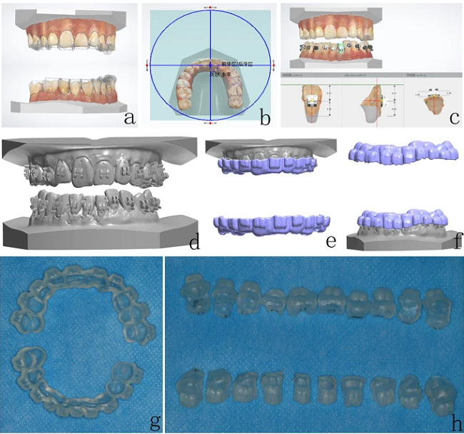
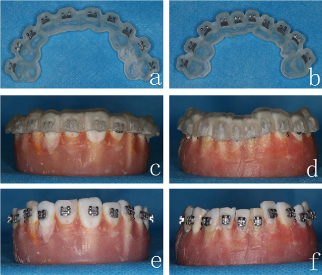
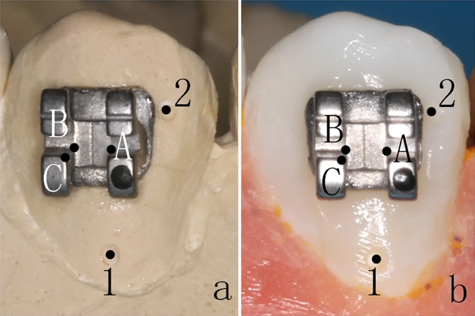
XT light-curable adhesives were applied to the base of the brackets,” the team explained about the indirect bonding procedure. “The 3D printing guides were then placed on the study models, and each border of the brackets was light-cured for 5 s.”

3D printing guides and indirect bonding procedure. 3D printing guide of the (a) maxillary and (b) mandibular dentitions. 3D printing guides placed on the (c) maxillary and (d) mandibular study models. Completion of bracket positioning on the (e) maxillary and (f) mandibular study models.

In making the traditional trays, the researchers used silicone-based materials to get impressions of the working models with intact marking points, and created plaster casts from the silicone molds.

“A thin layer of separation agents was applied to the cast tooth surfaces; then, the brackets were positioned and adhered on the crowns using 3 M Transbond™ XT light-curable adhesives and light-cured for 5 min,” they wrote. “Double-layer guide plates were manufactured by Erkoform-3D Thermoformer with a 1 mm inner layer (soft film) and 0.6 mm or 0.8 mm outer layer (hard film). Lastly, we trimmed the excess materials of the inner layer to 2 mm above the crowns and the outer layer until covering 2/3 of the brackets.”

The impression of (a) maxillary and (b) mandibular dentitions, and the plaster casts of (c) maxillary and (d) mandibular dentitions.

Bracket positioning on the (a-c) maxillary and (d-f) mandibular dentitions. Double-layer guide plate of the (g) maxillary and (h) mandibular dentitions.

For this indirect bonding procedure, the bracket were placed in the double-layer guide plates, with one solution applied to the surfaces of the teeth and another to the bracket base. Then, the guide plates were put on the study models, and after two minutes of fixation, the researchers removed the outer hard layer first, and then the inner soft layer.

Double-layer guide plates placed on the (a-c) maxillary and (d-f) mandibular study models. Completion of bracket positioning on the (g-i) maxillary and (j-l) mandibular study models.

Next, Materialise Mimics software was used to measure the distance between the marking points and bracket positions in the digital models of both the whole denture and single tooth designs for the 3D printed guide group, while electronic calipers measured the distance in the study models.

Electronic caliper.

Marking points on the plaster cast and study model.

SPSS software was used to analyze the distance.

“The accuracy of indirect bonding between 3D printing guide and double-layer guide plate was compared using the paired t-test. P < 0.05 indicated statistical significance,” they explained.

The data, reflected in the tables below, showed that there was no statistical difference in the accuracy of bracket positioning between the two types (p = 0.078), and that the 0.6 mm type in the double-layer guide group had much better results (p = 0.036) than the 0.8 mm one.

“We then further compared the accuracy of indirect bonding between 3D printing guides (whole denture type) and double-layer guide plates (0.6 mm), the results were comparable between two groups (P = 0.069),” they wrote. “However, indirect bonding using double-layer guide plates (0.6 mm) cost less chair-side time than the 3D printing guides group.”

Table 1: Comparison of different designs in 3D printing guide group.

Table 2: Comparison of different designs in double-layer guide plate group.

Table 3: Comparison of bracket positioning accuracy between 3D printing guide and double-layer guide plate.

However, while the data showed no statistical significance, the researchers noted that “the overall discrepancy before and after bracket transfer was lower in the 3D printing guides group.”

“This finding might be due to our in vitro study models with only mild malocclusion,” they explained. “Further in vivo studies in more severe clinical cases, such as malocclusion with torsion/tilting/overlapping, will be essential to investigate the efficacy and generalizability of 3D printing guides and double-layer guide plates.”

Discuss this and other 3D printing topics at 3DPrintBoard.com or share your thoughts below.

The post Comparing 3D-Printed and Traditional Guide Plates for Placing Orthodontic Brackets appeared first on 3DPrint.com | The Voice of 3D Printing / Additive Manufacturing.

Ireland: Characterizing Mechanisms of Metallic 3D Printing Powder Recycling

In order to cut down on material waste, and save money, laboratories will often reuse leftover metal AM powder. A trio of researchers from the I-Form Advanced Manufacturing Research Centre in Ireland published a paper, “X-ray Tomography, AFM and Nanoindentation Measurements for Recyclability Analysis of 316L Powders in 3D Printing Process,” focusing on better understanding and characterizing the mechanisms of metallic powder recycling, and evaluating ” the extent of porosity in the powder particles,” in order to optimize how many times recycled powder can actually be reused in the powder bed fusion process.

Many “risk-tolerant applications,” like in the aviation and biomedical industries, will not use recycled powder, because any part abnormalities that can be traced back to the material can be unsafe and expensive. Parts 3D printed out of recycled powder need to have mechanical properties, like hardness and effective modulus, that are comparable to those of fresh powder parts.

“In order to reuse the recycled powders in the secondary manufacturing cycles, a thorough characterization is essential to monitor the surface quality and microstructure variation of the powders affected by the laser heat within the 3D printer. Most powders are at risk of surface oxidation, clustering and porosity formation during the AM process and it’s environment [1,2],” they explained. “Our latest analysis confirms the oxidation and the population of porous particles increase in recycled powders as the major risky changes in stainless steel 316L powder [3,4].”

A common practice before reusing recycled powders is sieving, but this doesn’t lower the porosity or surface oxidation of the particles. Additionally, “the subsequent use of recycled powder” can change the final part’s mechanical strength, and not for the better.

“Here, we report our latest effort to measure the distribution of porosity formed in the recycled powders using the X-ray computing technique and correlate those analyses to the mechanical properties of the powders (hardness and effective modulus) obtained through AFM roughness measurements and nanoindentation technique,” the researchers wrote.

They used stainless steel 316L powder, and printed nine 5 x 5 x 5 mm test cubes on an EOSINT M 280 SLM 3D printer. They removed the recycled powder from the powder bed with a vacuum, and then sieved it before use; after the prints were complete, they collected sample powders again and labeled them as recycled powders.

“Both virgin and recycled powders were analyzed by number of techniques including XCT and Nanoindentation. XCT was performed by X-ray computed tomography (XCT) measurements were performed with a Xradia 500 Versa X-ray microscope with 80 KV, 7 W accelerating voltage and 2 µm threshold for 3D scan,” they wrote.

“To measure the roughness of the virgin and recycled powder particles, we performed Atomic Force Microscopy (AFM) and confocal microscopy using the Bruker Dimension ICON AFM. The average roughness was calculated using the Gwyddion software to remove the noise and applying the Median Filter on the images as a non-linear digital filtering technique.”

The researchers also ran nanoindentation on multiple powder particles, under a force of 250 µN for no more than ten seconds, in order to determine “the impact of porosity on the hardness and effective modulus of the recycled powders,” and used an optical microscope to identify pore areas on the powder.

XCT imaging of powder. (a) 3D rendered image of 900 recorded CT images, (b) region of interest, (c) internal pores in particles indicated in a 2D slice, (d) identified pores inside particles after image processing.

The XCT images were analyzed, and “a region of interest” was chosen, seen above, from which pore size and interior particle distribution were extracted.

AFM image on a particle showing the boundary of mold and steel and the area where surface roughness was measured.

Software was used to process the AFM topography images of both the virgin and recycled powders, and the team applied nanoindentation on different locations of the particles, with a force of 250 µm.

(a) powder particles placed on hardening mold for nanoindentation, and (b) an indent applied on a particle surface.

They determined that the reused powder particles had about 10% more porosity than the virgin powder, and the average roughness of the powder particle surfaces was 4.29 nm for the virgin powder and 5.49 nm for the recycled; this means that 3D printing “may increase the surface roughness of the recycled particles.” Nanoindentation measurements show that the recycled powder has an average hardness of 207 GPa, and an average effective modulus of 9.60 GPa, compared to an average of 236 GPa and 9.87 GPa for the virgin powder, “which can be correlated to porosities created beneath the surface.”

Pore size distribution in virgin and recycled powders extracted from image processing on XCT measurements.

“The pore size in recycled powders has a wider distribution compared to virgin counterpart. The main population of pore size is around 1-5 µm in virgin powder which slightly reduces to bigger size but for a smaller population. There are also bigger pores in recycled powder but with a smaller population,” they noted. “On the other hand, looking at higher pore population in virgin powder (around 10 µm size), we believe that the out-diffusion of metallic elements to the surface occurs during laser irradiation.”

Surface roughness plots from AFM measurements on powder particles. Average roughness calculated by Gwyiddion software.

The recycled powder hardness, which is smaller than in the virgin powder, “could be attributed to higher pore density in recycled particles,” since porosity causes the powder to be “more vulnerable to the applied force resulted in smaller hardness.”

While change in grain size of the powder particles can lead to reduced mechanical properties, the team’s AFM and SEM results did not show much grain redistribution in the recycled powder. But, their nanoindentation and XCT results did find that higher powder porosity can decrease both the hardness and modulus of the particles, which “will damage the mechanical properties of the manufactured parts.”

Hardness and effective modulus of fresh and virgin particles by nanoindentation.

“We have previously presented our achievement on surface and size analysis using SEM and XPS analysis. Here, we focused on pore distribution in both powders and correlated that to surface roughness, hardness and effective modulus obtained from nanoindentation analysis of the powder particles,” the researchers concluded. “The results indicate that pores population is about 10% more in recycled powders affected by the laser heat and oxygen inclusion/trap in the powder, which in turn, increases the surface roughness but reduces the hardness and modulus of the recycled powders. The pores are filled with gases (such as Argon or Oxygen) since these gases are not able to skip the melt and have a lower solubility in the melt throughout the solidification process.”

Discuss this and other 3D printing topics at 3DPrintBoard.com or share your thoughts below.

The post Ireland: Characterizing Mechanisms of Metallic 3D Printing Powder Recycling appeared first on 3DPrint.com | The Voice of 3D Printing / Additive Manufacturing.

University of Auckland: Growth-Induced Bending of 3D Printed Samples Based on PET-RAFT Polymerization

4D printed objects are 3D printed objects made with smart materials that respond to environmental stimuli, like liquid and heat, or return to an original form after deformation. Researchers from the University of Auckland published a paper regarding 3D printing and growth-induced bending based on photo electron/energy transfer reversible addition-fragmentation chain-transfer (PET-RAFT) polymerization.

By adding reversible deactivation radical polymerization (RDRP) constituents to a 3D printed structure to create “living” materials, which keep polymerizing on-demand, allows structures to be built with post-production functionality and modularity. But, as the Auckland team states, “this forms only half of the solution.”

RAFT processes have been used as a controlled polymerization technique to help with self-assembling macromolecules and block copolymerization. They previously demonstrated photo-RAFT polymerization 3D printing under several visible wavelengths, showing that a facile surface modification “could be performed on the samples after printing with a range of different monomers.”

Graphical abstract

“For this work, we further optimized the PET-RAFT 3D printing formulation and demonstrated the 3D printability using a commercial DLP 3D printer with standard 405nm light sources,” they wrote. “We also explore the 4D post-production modification capabilities of the 3D printed object using green light (λmax = 532 nm).”

The PET-RAFT recipe they used, below, adds a tertiary amine and the photo redox catalyst EY, the latter of which “is raised to an excited state (EY*) under irradiation where it then has several pathways to release its energy.” This is useful for 3D printing, since it’s a desirable “oxygen tolerant pathway.”

(A) Chemical structures of Eosin Y (EY), 2-(butylthiocarbonothioylthio) propanoic acid (BTPA), poly (ethylene glycol) diacrylate (PEGDA, average Mn = 250 g/mol), N, N-dimethylacrylamide (DMAm), and triethanolamine (TEtOHA). (B) Proposed combined PET-RAFT mechanism showing tertiary amine pathway by Qiao, Boyer, and Nomeir15, 23-25 (C) Reaction scheme for PET-RAFT polymerization of our 3D printing resin. (D) Schematic of a standard DLP 3D printer.

In their previous research, they used a 3D printing resin that was much slower to polymerize, and produced brittle objects. This time, they made several changes to the resin, such as replacing the RAFT agent CDTPA with BTPA and adjusting monomer composition.

“The development of an optimized 3D printing resin formula for use in a commercial DLP printer (λmax = 405nm, 101.86µW/cm2) was the first step in this research. Thus, several criteria were used to determine the quality of the optimized resin; the optimized resin must be able to hold its form in 60 seconds or less exposure time, the printed objects must have a good layer to layer resolution and binding, must be an accurate representation of the CAD model, and the resin must be stable enough to be reusable for consecutive runs,” the team explained.

They kept these criteria in mind while creating and testing new resin recipes with Photo Differential Scanning Calorimetry (Photo-DSC) and a 400-500 nm light source range.

“A monomer to RAFT agent ratio of 500:1 was chosen as a balance between a faster build speed, and a high enough RAFT concentration to perform post-production modifications,” they said. “For the first step in optimization we decided to compare two asymmetric RAFT agents, CDTPA and BTPA.”

Photo-DSC plot showing resin composition of [BTPA]: [PEGDA]: [EY]: [TEtOHA] = 1:500:0.01:20 (blue), [BTPA]: [PEGDA]: [DMAm]: [EY]: [TEtOHA] = 1:350:150:0.01:20 (green), [BTPA]: [PEGDA]: [DMAm]: [EY]: [TEtOHA] = 1:150:350:0.01:20 (red), [CDTPA]: [PEGDA]: [EY]: [TEOHA] = 1:500:0.01:20 (black), and [CDTPA]:[PEGDA]:[EY]:[TEA] = 1:200:0.01:2 (orange) form our previous PET-RAFT work, were compared to find an optimum new resin formula. The effects of different RAFT agent and comonomer ratio are noticeable on the maximum heat flow and the peak position of tmax.

The first formula, [BTPA]: [PEGDA]: [EY]: [TEtOHA] = 1:500:0.01:20, had a limited inhibition period, while [CDTPA]: [PEGDA]: [EY]: [TEtOHA] = 1:500:0.01:20 had a longer one.

“These results help to demonstrate the increase in polymerization rate that can be achieved by using BTPA in place of CDTPA,” they noted.

Because of its high glass transition temperature, DMAm was added as a comonomer in [PEGDA]: [DMAm] = 70:30 and 30:70 ratios. This slowed the polymerization rate for the resin formulas [BTPA]: [PEGDA]: [DMAm]: [EY]: [TEtOHA] = 1:350:150:0.01:20 and [BTPA]: [PEGDA]: [DMAm]: [EY]: [TEtOHA] = 1:150:350:0.01:20, but it was still faster than the CDTPA formulation. The researchers used this formulation to 3D print samples for dynamic mechanical analysis (DMA) and 4D post-production modification.

UV-Vis absorption spectra; (A) EB under 405nm (397.45µW/cm2) exposure for; initial (black), 10 (red), 20 (blue), 30 (magenta) and 40 minutes (olive). (B) EY under 405nm exposure for; initial, 10, 20, 30 and 40 minutes.

It’s important that photocatalysts don’t have issues like photobleaching or photodegradation during a photocatalytic process. Above, you can see a comparison in absorbance loss between organic photocatalysts EY and Erythrosin B (EB), “using their absorbance curves after different periods of 405 nm light irradiation.”

“Both showed a noticeable gradual decrease in UV absorbance which could likely be due to irreversible photodegradation, given that the effect remains after the sample has been stored overnight in a dark environment and measured again,” the team explained.

After longer periods of time, the EB solution started changing color, but this didn’t happen with the EY formulation, which is why the team kept it in their 3D-RAFT resin composition. A photostable catalyst, like EY, makes it possible for the 3D printing process to continue undisturbed.

The 3D printed samples that underwent DMA analysis were:

  • optimized RAFT resin before and after post-production modification
  • non-3D printed DMA sample by PET-RAFT polymerization in bulk
  • 3D printed free radical polymerization (FRP) control sample

The first type were 3D printed with a 30 µm thickness, a 60 second attachment time, and 30 seconds of exposure per each of the 53 layers. The second was fabricated with the same optimized formula “but polymerized in bulk using an external mold and a conventional 405nm lamp external,” while the FRP samples were printed with the same monomer composition and parameters but used a “conventional photoinitiator, phenylbis (2, 4, 6-trimethylbenzoyl) phosphine oxide (TPO).”

DMA plot showing (black) storage modulus (E’) and (black dashed) Tan δ from 3D printed DMA sample by normal FRP of resin formula [PEGDA]: [DMAm]: [TPO] = 350:150 and 2wt% TPO; (blue) the E’ and (blue dashed) Tan δ from 3D-RAFT printed DMA sample using resin formula [BTPA] :[PEGDA]: [DMAm]: [EY]: [TEtOHA] = 1:350:150:0.01:20; (green) the E’ and (green dashed) Tan δ from the post-print modified DMA sample; lastly (red) the E’ and (red dashed) Tan δ from the non-3D printed DMA sample prepared by normal PET-RAFT polymerization in bulk.

A temperature ramp (2˚C/min) was performed in order to find the storage modulus (E’) and glass transition temperature (Tg) of the samples, and there was a major change “in the E’ to 80 MPa and Tg to 15˚C” when the samples were compared to ones that weren’t 3D printed but instead polymerized in a mold.

“This layer-by-layer construction appeared to play a major role in the E’ at room temperature of the overall sample,” the team noted. “Each layer in the 3D printed sample received equal light irradiation (apart from attachment layer where specified), whereas in the bulk samples light had to penetrate through the entire thickness of the resin.”

Samples printed with RAFT resin had methyl methacrylate (MMA) monomer inserted post-production “in a growth medium devoid of solvent,” and DMA was used to analyze the effect of this modification on the prints’ mechanical properties, as well as “the relative effect on E’ and Tg of the sample.”

“The E’ at room temperature of the sample had decreased to 100 MPa but the Tg remained constant at about 19˚C,” they explained. “These limited changes can largely be attributed to the fact that BTPA is an asymmetric RAFT agent, all the growth being surface focused thus limiting the mechanical effects on the 3D printed RAFT sample.”

A1) CAD model for shapes upon 3 × 3 cm base. A2) Corresponding 3D-RAFT objects printed using DLP 3D printer. B1) Kiwi bird CAD model upon tiered base. B2) Corresponding 3D-RAFT printed object.

Once they determined the optimal RAFT 3D printing resin, the researchers designed CAD models for the objects they would print. They arranged different shapes, like triangles and Kiwi birds, on top of square and hexagonal base plates and circular coins, in order to see how the PET-RAFT resin formulation could handle features like corners and curves.

“These objects generally represented an accurate 3D print of the corresponding CAD model, confirming that the current 3D-RAFT resin was capable of printing 3D objects using a 405nm DLP 3D printer (λmax = 405 nm, 101.86µW/cm2),” they noted.

“Objects printed with 3D-RAFT also displayed an actual build speed of 2286 µm/hr (calculated from the actual height of printed objects over the full print time) consistent with that of the theoretical build speed, which is significantly faster than our previous PET-RAFT resin formula…”

Only limited shrinkage occurred on these prints, and after being washed for two days each in ethanol, THF, and DMSO, the team did not note a visible loss in yellow “arising from the trithiocarbonate group of the RAFT agent.” The 3D-RAFT resin was also reusable over more than ten prints.

“Having demonstrated that we could reliably print objects using our new RAFT resin, we endeavoured to demonstrate that these objects had retained their desired “living” behavior and could undergo post-production modification,” the team wrote.

They immersed half of a 3D-RAFT printed strip in a growth medium containing [BA]: [EY]: [TEtOHA] = 500:0.01:20 in DMSO. Then, a green 532 nm LED light was directed onto one of its faces, and after 15 minutes, “the strip showed moderate curvature.” They could see the strip was bending considerably after 15 more minutes, and it was also much softer, with the irradiated face paler than the other, and the growth medium was cloudier.

Optical images and graphical representations of growth-induced bending process. (A) The initial 3D-RAFT printed strip. (B) 3D-RAFT strip after 15 minutes monodirectional green light irradiation (532nm, 58.72µW/cm2) in a growth medium of DMSO and BA. (C) The same strip after 30 minutes monodirectional green light irradiation in the same growth medium. (D) Reaction scheme for the photo-catalyzed insertion of BA monomer under green light irradiation.

They next performed some control experiments. First, they tried the same thing with an FRP printed strip and a [PEGDA]: [DMAm] = 350:150 and 2wt% TPO growth medium, but this did not bend. A 3D-RAFT printed strip was left to soak in the original growth medium, without any light irradiation, for 24 hours, “to ensure that the bending was coming from growth rather than an alternate stimulus such as solvent swelling,” and saw no changes. Finally, they tried the same original process to return the bent 3D-RAFT strip back to its original form by shining the green light at it from the opposite direction. While it ultimately worked, it took three hours of irradiation to bend the strip back, which “indicates the unfavorability of introducing stress on the opposing side of the strip by our current methods.”

“To the best of our knowledge, this is the first demonstration of the growth of new material into the surface of an existing 3D printed object using RAFT polymerization to induce a bending response,” they concluded.

“In summary, we have further developed a 3D printable RAFT resin formula with an improved build speed up to 2286 µm/hr and demonstrated its ability to undergo 4D post-production transformation. We first demonstrated a facile method for growth induced bending of 3D-RAFT printed strips which opens an alternative pathway for movement and modification of these printed objects.”

Discuss this and other 3D printing topics at 3DPrintBoard.com or share your thoughts below.

The post University of Auckland: Growth-Induced Bending of 3D Printed Samples Based on PET-RAFT Polymerization appeared first on 3DPrint.com | The Voice of 3D Printing / Additive Manufacturing.