IP Security: Reverse Engineering to Test Vulnerability in 3D Printer Toolpaths

We hear a lot about engineering hardware and software and other accompanying technologies for 3D printing, so the idea of going in reverse may raise an eyebrow or two; however, scientists from the NYU Tandon School of Engineering are using machine learning and reverse engineering to test vulnerability in 3D printing toolpaths.

Security in 3D printing has been an ongoing concern for years now, and the focus of numerous different research studies. On a more topical level, there are worries about criminal factions using the technology for evil purposes like fabricating skimmers, making guns for nefarious purposes, and even 3D printing packaging for illicit drugs. On a much deeper, more analytical level, there is vulnerability to cyberterrorism, whether in tampering with critical parts for aerospace applications, creating product defects and causing safety issues and liability, or even interfering in military operations.

The researchers, led by Nikhil Gupta, a professor in the Department of Mechanical and Aerospace Engineering, enlighten the public on worries that most 3D printing users would never consider: the potential for stolen trade secrets through analysis of layered materials. Gupta and his researchers have been tackling this issue for years now too, examining risks throughout the online world, but with an emphasis on the potential for cyberterrorism in 3D printed parts.

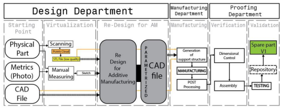
For 3D printed parts to offer functionality and high performance, many factors are “fine-tuned,” and this is what an interloper could uncover in analyzing toolpaths contained in CAD files; in fact, the researchers consider much of that data to be easily copied and stolen.

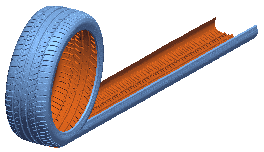
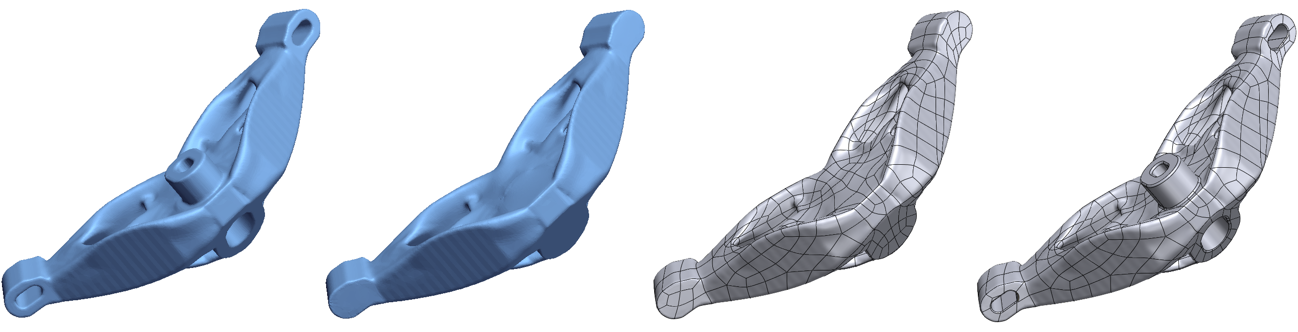
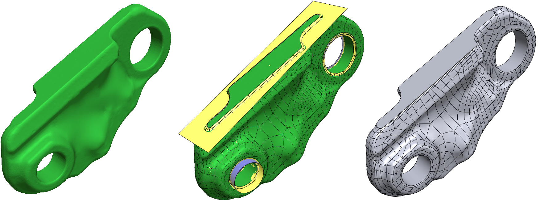
Outlined in their most recent paper, “Reverse engineering of additive manufactured composite part by toolpath reconstruction using imaging and machine learning,” the authors explain that as cyberthieves learn how to reverse engineer parameters like fiber size, volume fraction, and direction, there is greater opportunity for both “counterfeiting and unauthorized production of high-quality parts.”

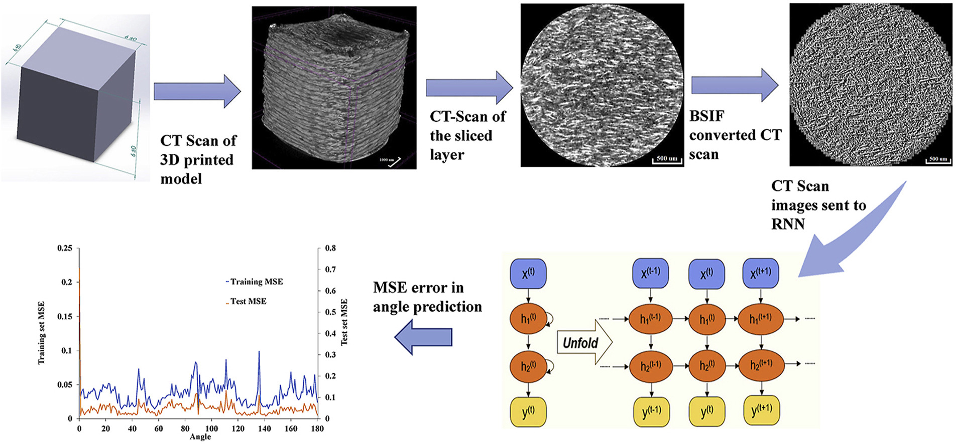
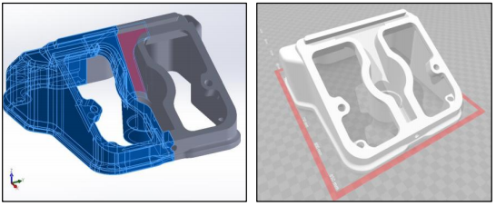
“A dimensional accuracy with only 0.33% difference is achieved for the reverse engineered model,” stated the researchers.

Also working on the project were NYU Tandon grad students Kaushik Yanamandra, Guan Lin Chen, Xianbo Xu, and Gary Mac, demonstrating that fiber orientation can be intercepted with micro-CT scanned images. Loss of trade secrets means stolen intellectual property in most cases, along with what could be substantial investments in research and development costs too.

While spying via 3D printing presents obvious gray area regarding legality, theft of intellectual property is often taken much less seriously outside of the US—with countries like China being known for their irreverence toward IP law.

“Machine learning methods are being used in design of complex parts but, as the study shows, they can be a double-edged sword, making reverse engineering also easier,” said Gupta. “The security concerns should also be a consideration during the design process and unclonable toolpaths should be developed in the future research.”

[Source / Images: ‘Machine learning reveals vulnerabilities in 3D printed carbon-fiber composites’]

The post IP Security: Reverse Engineering to Test Vulnerability in 3D Printer Toolpaths appeared first on 3DPrint.com | The Voice of 3D Printing / Additive Manufacturing.

3D Systems Streamlines Software for Reverse Engineering

3D Systems has announced the latest versions of its Geomagic Design X and Geomagic Wrap  software, this time claiming “first-to-market capabilities” for streamlining workflows and improving design precision.

New features within Design X meant to exemplify this claim include improved workflows and expanded modeling pathways for complex, revolved parts. In particular, the software includes an Unroll/Reroll function that makes it possible to model said components in a simpler, yet more precise fashion. The tool allows users to extract a 2D sketch automatically so that they can modify it and then reroll it, purportedly reducing the need for trial and error typically associated with modeling these geometries. In turn, part precision, efficiency and downstream usability are said to be increased. For a comparison of the revolve process in another CAD software, see here.

Unrolling of a 3D scan of a tire for mold modeling in Geomagic Design X. Image courtesy of 3D Systems.

The software also includes a new Selective Surfacing Feature, which is meant to make modeling with 3D scans faster and more precise. According to the company, users will be able to “highlight portions of the a (using mesh selection tools, or curves) and surface just those portions in a way that makes downstream ‘hybrid modeling’ much easier.”

3D Systems has also released a method for previewing yet-to-be fully released features. Geomagic Design X customers on-maintenance can access R&D capabilities using plugins that will allow the company to receive feedback on these tools before they are released more generally.

Hybrid Modeling Workflow of a topology optimized part in Geomagic Design X. Image courtesy of 3D Systems.

Geomagic Wrap 2021 offers a variety of new capabilities for manipulating 3D scan data and imported files for various applications. This includes a new scripting editor enabling engineers to customize their workflow using Python that allow for the use of new tools that include ‘auto complete’ and ‘contextual highlighting’. API documentation for the software will be continuously updated online.

Geomagic Design X 2020 streamlines Hybrid Modeling Workflows for molding, casting, topology optimization, and medical applications. Image courtesy of 3D Systems.

Texture manipulation tools are integrated directly into Geomagic Wrap 2021 that make it possible to manipulate and re-touch colors, logos and other visual elements obtained from 3D scans within the same workflow. A new HD Mesh Construction tool is meant to make the construction of 3D data from point clouds more effective and aid in dealing with challenges associated with large data sets and scans with missing information.

Example of using the updated scripting editor showing the real time error tracking, contextual highlighting, and autocomplete tools. Image courtesy of 3D Systems.

All of these tools help to strengthen 3D Systems larger strategy of cohesion across its digital manufacturing products, which also include additive manufacturing, virtual reality and simulation systems, inspection software and more. Altogether, the company has a solutions for many steps along the design-to-manufacturing pipeline (or “digital thread”).

To be discussed in an upcoming report from SmarTech Analysis on software in the AM industry (and update to its 2017 report), 3D Systems has one of the more diverse portfolios of 3D printing software. The Geomagic suite, which also includes design and haptic sculpting tools, makes the company unique among 3D printer manufacturers in part for the 3D scanning and inspection software included. Meanwhile, its metal build preparation software, 3DXPert, has even been sold to customers who didn’t even have 3D Systems printers and the company’s CAM solutions, Cimatron and GibbsCAM, give it a leg into the toolmaking industry. In total, SmarTech estimates 3D Systems to hold a significant share of the market for both 3D printing and scanning software. The total value of the AM software industry is projected by SmarTech to be worth $2.4 billion by 2026.

Modeling of a complex part with cylindrical drum slots in Geomagic Design X. Image courtesy of 3D Systems.

It competes against a number of other companies, both 3D printer manufacturers and software developers. This includes Stratasys, which has grabbed and increasing amount of the software space with the acquisition and development of GrabCAD, as well as Materialise, Autodesk and Dassault Systèmes.

Geomagic Design X 2020 will be made available late May 2020, while general availability of Geomagic Wrap 2021 is slated for late July 2020.

The post 3D Systems Streamlines Software for Reverse Engineering appeared first on 3DPrint.com | The Voice of 3D Printing / Additive Manufacturing.

Bunnie Huang tears down a Formlabs Form 3 “from the exterior shell down to the lone galvanometer” @bunniestudios @formlabs

The brilliant, ever-curious Andrew “bunnie” Huang has posted an exhaustive tear down of the Formlabs Form 3 SLA 3D printer, released last year. In the nearly 7,000-word article, bunnie offers up his first impressions, does some test printing, and then gets to work deconstructing the machine. He identifies some of the machine’s strengths and weaknesses, speculates on the reasoning behind various design decisions, and attempts to identify parts sources. He even includes a sound clip of what the LPU (light processing unit) sounds like as it scans.

One problem that became immediately evident to me, however, was a lack of a way to put the Form 3 into standby. I searched through the UI for a soft-standby option, but couldn’t find it. Perhaps it’s there, but it’s just very well hidden. However, the lack of a “hard” button to turn the system on from standby is possibly indicative of a deliberate choice to eliminate standby as an option. For good print quality, it seems the resin must be pre-heated to 30C, a process that could take quite some time in facilities that are kept cold or not heated. By maintaining the resin temperature even when the printer is not in use, Formlabs can reduce the “first print of the day” time substantially. Fortunately, Formlabs came up with a clever way to recycle waste heat from the electronics to heat the resin; we’ll go into that in more detail later.

The other thing that set the Form 3 apart from its predecessors is that when I looked inside, there were no optics in sight. Where I had expected to be staring at a galvanometer or mirror assembly, there was nothing but an empty metal pan, a lead screw, and a rather-serious looking metal box on the right hand side. I knew at this point the Form 3 was no incremental improvement over the Form 2: it was a clean-sheet redesign of their printing architecture.

Thoughtful tear downs like this do the maker community a great service — bunnie field-strips it so you don’t have to. It’s also wonderful that Formlabs themselves offered up this unit to the slaughter.

If you’re interested in seeing and comparing his tear downs of the Form 1 and Form 2, he has links to these articles in the first paragraph of the piece.

How to Make Apple’s Mac Pro Holes @isonno #Apple #MacPro

Via J. Peterson’s blog – Apple’s recently introduced Mac Pro features a distinctive pattern of holes on the front grill… that pattern is very appealing, and re-creating it is a fun exercise.

The best clue about the pattern comes from this page pitching the product. About halfway down, by the heading “More air than metal” is a short video clip showing how the hemispherical holes are milled to create the pattern.

With a bit of trig, you can find half the horizontal spacing x by using the right triangle formed by that line, x and the side of the equilateral triangle. The angle from the vertical center line to the equilateral triangle edge is half of π/3, π/6. So, x=2r tan(π/6) and 2x is the horizontal spacing of the circles.

The blog goes on to use trigonometry to calculate the opposite hole positioning and with some pixel counting, some thickness estimates.

So to CAD this up, all you need to do is start with a rectangular block of thickness t, and use the formulas above to place the centers of the spheres (with diameter 2r) on the front and back of the block.

If you just want to quickly print or look at the result in 3D, there are some sample STL files posted on Thingiverse.

German Armed Forces Use 3D Printing to Redesign an Obsolete Part

The German Armed Forces are working on using 3D printing directly in the field, as described in a study entitled “Characteristics of a metal additive manufacturing process for the production of spare parts.” The plan is to re-engineer machine parts that get worn out during deployment, create a printable file, and send it back to the area of operation, where the troops will then 3D print the part. This sounds simple, and the armed forces in other countries are working on 3D printing in the field as well. But as the authors of the paper point out, there are many uncertainties in the process.

“Usually, the development team does not exactly know the exact dimensions nor functional boundary conditions of the part in question,” they state. “It is incumbent upon the team to collect lacking information to a sufficient level of confidence.”

The authors discuss an agile development approach. Agility, as defined by the paper, is “the ability to quickly and cooperatively react to changes in unpredictable environments in order to meet demands efficiently and effectively.” The paper takes a look at a specific case study carried out by the German Armed Forces. When the military needs a spare part 3D printed, the work is carried out by WiWeB, the federal research institution Bundeswehr Research Institute for Materials, Fuels and Lubricants.

When a request comes in for a 3D printed component, the work is carried out by two teams. The design team is responsible for generating a 3D printable file, and the manufacturing team is responsible for the actual 3D printing and post-processing. After the part is completed, the proofing department is responsible for ensuring quality control and certifications in some cases.

In the case study, a worn-out valve cover for a diesel generator was sent to the design team for redesigning, but no documentation regarding the original dimensions, material or other specifications was available. The team was able to deduce from its complexity and geometry that the part had originally been cast, and material analysis showed that it was made from a special aluminum alloy, AlSi10.

“In practice, such parts are commonly not considered to tend to wear, so they are not available in warehouse,” the authors state. “Since the machinery using this component date from several decades ago the acquisition of such a spare part, especially after a long period of time after its production, is practically impossible. Given the complex shape as well as the non-availability of the spare part, this valve cover was predestined to be remanufactured using AM.”

The first step was to scan the part using a 3D scanner. The data acquisition was conducted using Polyworks Inspector, with multiple scans being merged into a single file.

“Nevertheless, manual post-processing was necessary to adjust the homogenous structures of the part due to the occurrence of holes,” the authors continue. “Challenges throughout the scanning process such as unwanted noise led to imprecise measurements, resulting in false point assignments. Such effects make it necessary to apply software-based corrections in order to homogenize the surface structure of the part. Coupled with signs of wear, the results of the scanning were not sufficient, and the part had to be redesigned manually in the reverse engineering process.”

Thanks to the expertise of the design team, it was possible to delete and/or modify features that were not critical to the part’s function and were inherent to the original manufacturing process. In this example, the draft angles on the side faces and the extraction supports for the casting mold were obvious features of subtractive manufacturing, and could be removed for additive. This phase is called Design for Additive Manufacturing (DfAM) and takes advantage of 3D printing’s ability to more efficiently produce the component.

Support structures were then generated, and the part was manufactured using SLM. The print took 37 hours with an additional two hours of heat treatment to reduce residual stresses, and another hour to grind off the support structures.

“It is important to emphasize that these processes for spare parts production, although driven by military scientific research, have applications in many other different industries, and their participation will be more important in the coming years with the massification of AM and the arrival of Industry 4.0,” the authors conclude. “Also, metal AM is successively gaining importance due to the flexibility of the process itself and its potential applications, however guidelines for designing are necessary. Since having to deal with several uncertainties throughout different stages of the process, the adaption of certain principles of agile hardware development appears to be reasonable.”

Authors of the paper include Alexander Atzberger, Joaquin Montero, Tobias Sebastian Schmidt, Kristin Paetzold and M. Bleckmann.

Discuss this and other 3D printing topics at 3DPrintBoard.com or share your thoughts below. 

3D Printing News Briefs: September 22, 2018

In today’s 3D Printing News Briefs, we’ve got the speaker lineup for next month’s NAMIC Global Additive Manufacturing Summit in Singapore. Prusa and Cincinnati Incorporated are both releasing new 3D printing materials, and 3D Center is collaborating with 3YOURMIND to launch a 3D printing platform for the Scandinavian market. A British car manufacturer turns to Stratasys 3D printing for prototyping purposes, and a student used reverse engineering and 3D printing to redesign a Nintendo 64 joystick system.

2018 NAMIC Global Additive Manufacturing Summit Speakers

On October 17th and 18th, the 2018 Global Additive Manufacturing Summit, conducted by Singapore’s National Additive Manufacturing Innovation Cluster (NAMIC), will be held, and co-located as part of Industrial Transformation ASIA-PACIFIC. Hosted by NTUitive, the summit, which is said to be the country’s largest gathering of additive manufacturing experts, will highlight key AM opportunities and developments in multiple applications, such as aerospace, automotive, biomedical, building and construction, marine, and transportation.

This is the last week to purchase your ticket at the early bird rates. After seeing the line-up of speakers coming to the event, this is an event you definitely won’t want to miss. Some of the speakers include Dr. Behrang Poorganji, the Head of Materials Development for GE Additive: Apis Cor’s Anna Cheniuntai, R&D and Business Development; Kelvin Wee, the APAC Sales Director for Materialise; and Professor Paul C. Ho, with the Department of Pharmacy at the National University of Singapore. You can register for the 2018 NAMIC Global Additive Manufacturing Summit here.

Prusa Releasing In-House 3D Printing Filament

Fresh off the multi-material upgrade for its Prusa i3 MK3/MK2.5, Prusa has more good news – this week, the company released its new filament, Prusament, which is made entirely in-house. CEO and Founder, Josef Průša, said that the company was not happy with the over-exaggerated quality and specs that “most filament companies claim but don’t deliver,” which continued to cause its users to have issues poor print quality and jams.

“So we built a factory and just started to sell our own filament,” Průša told 3DPrint.com. “It took us over a year but we have something pretty special. We guarantee 20µm precision and every spool is traceable on our website, where you can see the full inspection report. I believe we are the only one to do this and hope to set a precedent.”

Check out the sample spool of Prusament for yourself – you’ll see that Prusa isn’t messing around.

Cincinnati Incorporated Launches New Carbon Fiber Material

Cincinnati Incorporated has developed a new material for its SAAM that is ideal for custom tooling and fixture applications. The carbon fiber resin creates a high strength-to-weight ratio and superior surface finishes.

Another company with a new 3D printing material launch this week is Cincinnati Incorporated (CI) – it just released a new carbon fiber resin material for its SAAM (Small Area Additive Manufacturing) 3D printing system. Because it’s been reinforced with carbon fiber, the lightweight, impact-resistant material is durable, stiff, and has low warping, along with accurate parts featuring advanced inter-layer adhesion results. It also has excellent surface finish, making it a good choice for applications in assembly, CMM, CNC fixtures, custom tooling, and has a very high strength-to-weight ratio.


Morgan Motor Company Turns to Stratasys 3D Printing for Prototyping

Family-owned British motor car manufacturer Morgan Motor Company is no stranger to 3D printing, and recently turned to the technology again for help with prototyping on the factory floor. In order to get rid of the endless talks with suppliers and lower the time to market, the company, which manufactures roughly 1,000 vehicles per year, invested in a Stratasys Fortus 250mc from Tri-Tech 3D, a Stratasys reseller in the UK.

“Since the introduction of 3D printing, using the Stratasys Fortus 250mc, Morgan have been able to try more daring designs within research and development,” said Tom Morris, a CAD technician with Morgan Motor Company. “It’s given us the opportunity to take these designs, trial them early on, giving us physical samples, which essentially cuts out the whole quoting process of liaising with suppliers, delivering these parts back to Morgan. Morgan are a low volume vehicle manufacturer, so the ability to be able to design parts on CAD, 3D print them, and take them to the shop floor at a very quick rate is vital to our success as a business.”

Watch the video below to learn more:

Fixing Nintendo 64 Joystick with Reverse Engineering and 3D Printing

California Polytechnic (Cal Poly) student and retro video gaming fan Nam Le was tired of having to find replacement controller joysticks for Nintendo 64 systems – a common problem many Nintendo fans have dealt with. So he took matters into his own hands, and contacted 3D Hubs for help fixing the problem. Le ended up reverse engineering the nearly 20-year-old components, 3D printing them, and redesigning the entire joystick system. It took him three months to disassemble the original controller, measure the components, and design them in CAD – a very impressive task, as he’d only ever taken a basic 3D modeling introduction class.

He determined that the joystick’s whole assembly would wear down over time, causing part failure, and designed the new components so that they were very sturdy and easy to replace. Le 3D printed the gear teeth and housing with Visijet M3 Crystal material, and 3D Hubs manufactured his redesigned joystick out of Nylon PA12 material on an HP Multi Jet Fusion 3D printer.

“Generally, harder materials won’t be worn by materials of a lower hardness,” Le explained about his material choice. “The result is having only one part wear compared to every old component wearing. Every once in a while the stick will have to be replaced, but it takes a longer time to wear and is a better cheap alternative than buying a new controller.”

Six months in, Le’s 3D printed prototype joystick controller shows no signs of breaking.

Discuss these stories and other 3D printing topics at 3DPrintBoard.com or share your thoughts in the Facebook comments below.