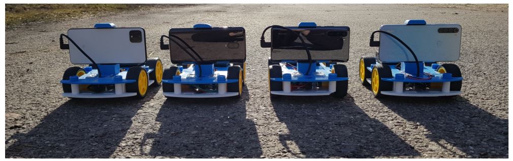
Researchers at Intel Labs have developed a smart robot that anyone with a smartphone can build, using open source code, a 3D printer, and $50. What is different with this 3D printed robot is that the smartphone isn’t just used to control the robot, as with devices such as MobBob or Qualcomms Micro Rover, but is used directly as the ‘brains’ of the bot, leveraging the advanced features and operating systems in today’s smartphones to enable high-quality sensing and computation, while improving affordability, accessibility and scalability—all within a $50 budget (not including the smartphone).
While there have been efforts previously at making robot technology affordable and scalable, compromises have been made either in design, functionality, or performance. Relatively expensive robots in this area of research can cost between $2,000-$5,000, while mobile-based robots are significantly less expensive, yet still fall between $250-500 in cost, such as the AWS DeepRacer, DJI Robomaster S1, Nvidia JetBot, and DukieBot.
As the study says, “the aforementioned projects use the smartphone as a remote control for teleoperation, offload data to a server for processing, or rely on commercial or outdated hardware and software. In contrast, our platform turns a smartphone into the brain of a fully autonomous robot with onboard sensing and computation.”
With this approach, Intel researchers have leveraged the advantages of today’s smartphones to enable navigationand real-time sensing and computation for a wheeled robot body that costs less than $50. The features of smartphones that make this possible include advanced imaging technology, processing power, navigation, connectivity, sensors, AI accelerators for neural network inference, rapidly upgraded and evolving software and hardware ecosystems. In turn, the ‘OpenBot’ is capable of advanced applications such as person following and autonomous navigation.
While a large part of the cost, about 40%, is that of the batteries, the price can be further reduced by scaling production, as more units are made. The top plate with the phone mount and the bottom cover, weighing 146g and 103g respectively, are 3D printed in PLA and take about 23 hours in total to 3D print using an Ultimaker.
Image Courtesy of Intel Labs
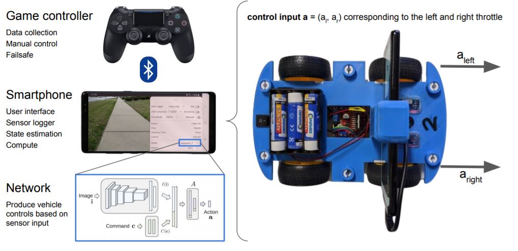
The Android application allows for connectivity, processing and audiovisual sensory inputs (camera, gyroscope, accelerometer, magnetometer, ambient light sensor, barometer). Common game controllers can be connected via Bluetooth to remotely operate the OpenBot. The learning-based algorithms, unlike classic motion planning algorithms, uses neural network processing to detect objects or people, and navigate autonomously.
OpenBot smartphone-based system Image Courtesy of Intel Labs
Explaining the difference it makes in using an widely available, constantly upgraded, open-platform such as Android, as opposed to specific custom software solutions, the study states,
“In contrast to other robots, our platform has an abundance of processing power, communication interfaces, and sensors provided by the smartphone. Existing robots often rely on custom software ecosystems, which require dedicated lab personnel who maintain the code, implement new features, and implement drivers for new sensors. In contrast, we use Android, one of the largest constantly evolving software ecosystems. All the low-level software for sensor integration and processing already exists and improves without any additional effort by the robotics community. All sensors are already synchronized on the same clock, obviating what is now a major challenge for many existing robots.”
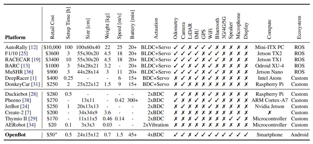
Comparison of Wheeled-robotics solutions Image Courtesy of Intel Labs
The advantages of this approach to improving the accessibility and scalability in robotics is more than obvious when comparing the features and specifications across wheeled-robotics platforms. With nearly all the features available, an open Android operating system, using any smartphone available today, not only to control, but to drive learning-based algorithms and AI-based applications in person following and autonomous navigation, and its cost-effectiveness, the OpenBot from Intel Labs is leaps and bounds ahead of any other low-cost robotic solution available publicly.
Pathfinder is a fan favorite character from the game Apex Legends. In this new guide, John Park shows you how to build your own interactive desktop Pathfinder desktop companion, complete with AdafruitPyPortal chest screen, voiceover lines from the the game, and glowing LED robot eye!
We’ll build Pathfinder using 3D printed parts, Sugru moldable glue, and an array of electronics, all running on the touch-screen display PyPortal coded with CircuitPython.
Note: This project was built in partnership with Sugru — check out this link for a chance to win a 3D printer to help you build your own Pathfinder.
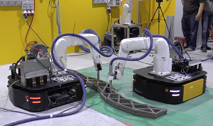
Adoption of concrete 3D printing is limited because of problems like lack of mobility and small size, and the use of synchronized, mobile robots is an excellent place to start working on the issue of scalability. But now, Professor Cuong and his team are taking things to the next level. They’re still using mobile robots for a print-while-moving approach, but instead of a pair systems, they’ve developed a single-robot industrial AM platform that can complete large-scale construction printing all by itself.
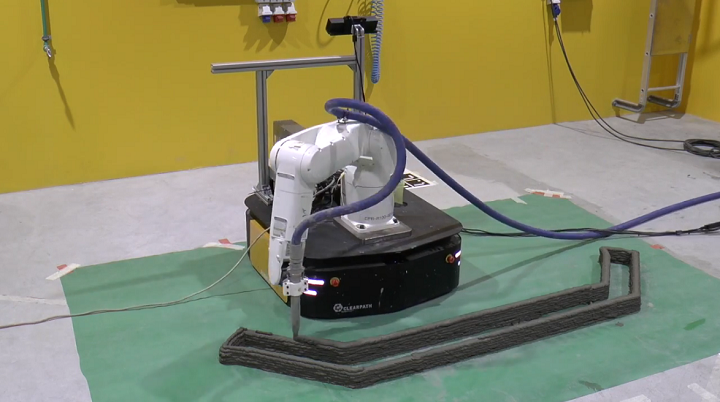
“Our system is mounted on a mobile robot. The ability to move the robot base in space allows our robot to print structures that are larger than itself,” Professor Cuong explained. “Also, having a mobile base makes it easier to bring the robot into the construction site and move it around inside.”
The abstract reads, “Building and Construction have recently become an exciting application ground for robotics. In particular, rapid progress in material formulation and in robotics technology has made robotic 3D Printing of concrete a promising technique for in-situ construction. Yet, scalability remains an important hurdle to widespread adoption: the printing systems (gantry-based or arm-based) are often much larger than the structure be printed, hence cumbersome. Recently, a mobile printing system – a manipulator mounted on a mobile base – was proposed to alleviate this issue: such a system, by moving its base, can potentially print a structure larger than itself. However, the proposed system could only print while being stationary, imposing thereby a limit on the size of structures that can be printed in a single take. Here, we develop a system that implements the printing-while-moving paradigm, which enables printing single-piece structures of arbitrary sizes with a single robot. This development requires solving motion planning, localization, and motion control problems that are specific to mobile 3D Printing.”
This system only needs one robot to print differently sized single-piece structures, which also helps to ensure better structural properties.
The mobile robotic 3D printing system
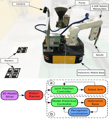
Typically, construction materials wider than the construction 3D printing system’s gantry foothold distance can’t be printed. That’s because a printed structure’s dimensions are constrained by one of three things: the robot arm’s reach, the gantry’s restricted volume, or the framework which enables the printhead to move along a particular axis. But the NTU researchers have enabled their system to move in any direction, so long as it’s on a flat surface, by mounting an industrial robot manipulator to a wheeled base. Then, a hose is used to connect the platform’s manipulator flange nozzle to a pump.
The robot manipulator’s motions, and those of the mobile platform, are painstakingly planned out in this new system in order to achieve a coordinated effort. It uses feedback motion control, and highly accurate robot localization, to make sure that the nozzle deposits the concrete material at the right pace in the correct location. By placing a camera on the back of the mobile base, its “localization system” works better over a larger surface area.
Model of NTU’s 3D printing system setup and printing process pipeline
The NTU research team claims that their printing-while-moving system can increase the size of structures that one robot can fabricate. To prove it, they used the platform to 3D print a single-piece 210 x 45 x 10 cm concrete structure, which is definitely larger than the robotic arm’s 87 cm reach. This system could significantly increase the effectiveness of 3D construction printing. But, their work is not yet done, as the system does still have some limitations, particularly in terms of uneven work areas.
Professor Cuong explained, “We’re planning to add collaborative features to our robot. The idea is to have a human operator take the robot by hand and move it around the construction site, towards the desired location, guiding it to achieve high-precision assembly.”
Discuss this story and other 3D printing topics at 3DPrintBoard.com or share your thoughts in the Facebook comments below.
My Track Technology (MTT) is an eco-friendly, electric remote-controlled track vehicle built to operate in extreme terrains. Its low center of gravity, resistance to the elements and autonomy make it a crucial new tool for a wide range of civilian and military applications including emergency and disaster rescues and agricultural functions.
Partnered with Shapeways, the makers of MTT were able to use 3D printing to cut substantial time and costs in their production process by rapidly prototyping designs and printing strong, end-use ready parts that can resist the elements.
We interviewed Michael Martel from MTT to find out how MTT has utilized Shapeways’ 3D printing technology to ramp up production with speed and efficiency.
What is your name and your role at My Track Technology?
My name is Michael
Martel and I’m in charge of the MTT product development.
How did My Track Technology start?
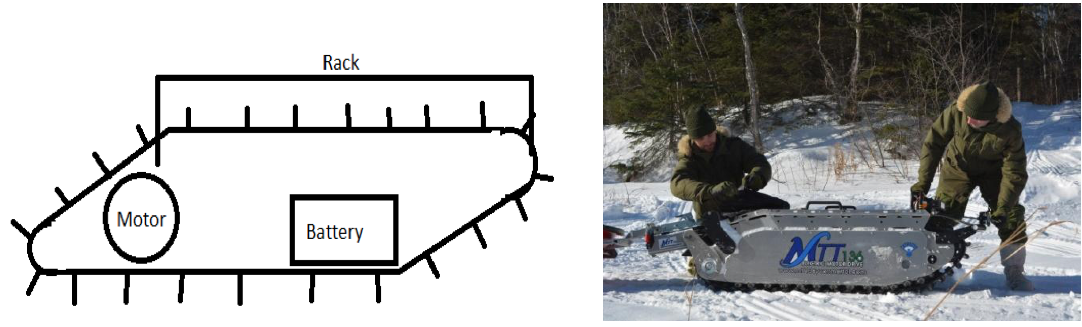
10 years ago my
father and I were discussing a product that can enhance human power but as
small as possible to be able to go where a person can walk. The main goal was
to be able to get someone that is injured out of deep forest and at the same
time bring reduced mobility
persons to extreme places.
From a sketch in 2010 (left) to a fully functional machine in 2020 (right).
What kinds of customers can MTT benefit?
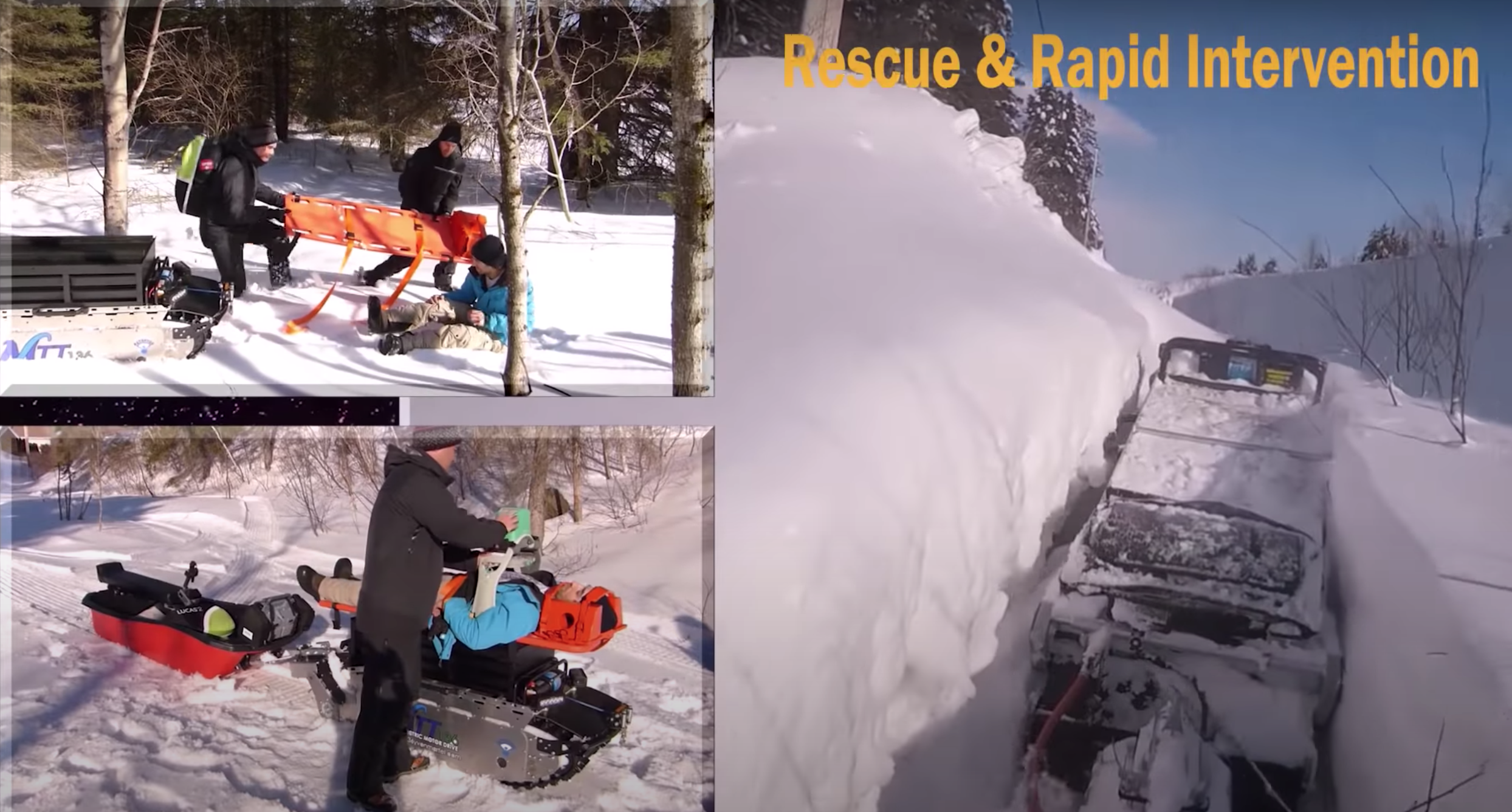
Our customers are very broad. First, there is the military for rescue and material carrying. Mining for carrying material underground without any fumes and CO2 that has to be ventilated out of the mine. Wildfire suppression help, carrying water pumps and equipment. Also fat bike trails grooming, for agriculture use on wet fields or carrying a freezer in the field for fruits and vegetable harvesting. Replacing a generator on construction sites with MTT-154 onboard 2000W inverter, and much much more.
My Track Technology’s machine used in rescue and rapid intervention. Photo source: My Track Technology
How did you find Shapeways?
Four years
ago one of my electronic employees bought a cheap FDM printer that he assembled himself. At that time I was very skeptical of 3D printing,
I was thinking it was only for toys and figurines. Nevertheless I let him try
some joystick parts. I was at the time building it with a laser cut aluminum
sheet, bent and welded to make an enclosed case. His part with FDM (PLA) was so successful that we
used it for our vehicle for about a year, very amazing. The problem with this
part was the surface finish, time to print and resistance to wet environments.
I was so impressed by this test that I decided
to learn more on 3D printing methods, suppliers and more. This is when I came
to Shapeways’ website and was very impressed
by the technical information and production
capabilities.
I then decided to
manufacture a couple of parts at Shapeways and I have
never been disappointed since. Shapeways is not the
least expensive but I tested many suppliers over the years and I did a lot of
cold temperature testing. Shapeways always has the strongest and nicer finished parts.
Unless you have $100,000 or more to invest in an SLS or HP printer you will never have the quality, robustness, precision and surface finish of a Shapeways part.
What are the benefits of using Shapeways over an in-office printer?
When buying a printer you have an amazing amount of choice offered to you. The problem is to have a printer for all of the applications. The size of the parts, the surface finish, the resistance and the productivity of this printer are all to be considered. Unless you have $100,000 or more to invest in an SLS or HP printer you will never have the quality, robustness, precision and surface finish of a Shapeways part. Shapeways is a one-stop shop for 3D printing projects. They have multiple machines to accommodate all the requirements of all special projects. So for us Shapeways has been a great partner to reach all of our goals, present and future.
What are the benefits of 3D printing with Shapeways over other manufacturing methods?
Speed, cost and simplicity. When our 3D drawing is finished we don’t have to produce fabrication drawings. We just upload the 3D file on Shapeways’ website. Very simple. We also do not have to build a mold for 1 up to 50 parts. It’s very great cost saving. Later when the design is perfect we can build a mold and be confident that the mold will meet our requirements. We are also not limited to a particular shape with 3D printing, practically every shape is possible. Finally, the precision, repeatability and tolerances are better than most of the others manufacturing methods.
“The precision, repeatability and tolerances [of 3D printing technology] are better than most of the others manufacturing methods
What aspect of My Track Technology production do you use 3D printing and Shapeways for?
We are right now
moving to production and most of the parts that had previously been tested with
3D printing are now thermo or injection molded. 3D printing saves us an amazing amount of money by testing
different designs quickly. When the design is
confirmed the mold can be built with the peace of mind that this part works perfectly well.
The other 10 parts
that are needed for an
MTT-154 2020 will continue to be built with 3D
printing technologies. Up to about 100 MTT-154 units per year it totally makes
sense to print parts in Nylon. We save the initial cost of the mold and we can design parts
that are impossible to manufacture with a traditional mold.
What materials do you use?
Right now we mostly use SLS, with Nylon PA12 (Versatile Plastic), dyed black. We also use rubber like TPU to create custom grommets.
How does working with Shapeways affect the speed of your manufacturing?
In our MTT machine there are about 20 plastic parts. Last year we were in a very big rush to do a test with the US military and we had no time to build 20 molds for every single part. We saved at least 6 months (concept, drawing for molding, mold building and parts production) by 3D printing with Shapeways.
How about any cost savings?
For 20 plastic parts the average cost of a mold is $3500 * 20 = 70,000 USD. This money would have been a very big gamble knowing that we were unsure if these parts would meet the functionality, design and resistance we needed. $70K is a lot of money for a startup. It’s manageable, but $70K without any guarantee that this mold will be useful in the future is unacceptable.
Video source: My Track Technology
What is the most important aspect of working with Shapeways for you?
First, when we want
a strong part I know that Shapeways will not disappoint us. Also the website is
very easy to use, and I like the freedom to choose the shipping you want
depending on the requirement of a particular project. The quality control is
also excellent because I never return a part. Finally, the service when I need
information is excellent.
Can you share any current or future goals for My Track Technology?
The goal right now
is really to move to production and send machines to the customers that have
reserved these vehicles in the past. The product we sell right now is our
MTT-154 2020, with the possibilities to have only one unit with a trailer/sled
or with the flip of a switch multiple units coupled together for special military and industrial
applications.
Finally, we have orders for some small MTT-like robots. The frame will be built entirely in SLS printing at Shapeways very soon.
The next stage in 2021-2022 will be remote control with satellite or 4G and autonomous capabilities.
Efficient Manufacturing with 3D Printing
My Track Technology’s vast range of potential applications will see it become an essential tool for assisting humans in navigating challenging terrains and environments. Using 3D printing has made MTT’s production process much more efficient and affordable and shows how 3D printing can contribute to smarter manufacturing.
If you don’t remember the stunning and technical work from Anouk Wipprecht—the Dutch fashion design working on “rethinking fashion in the age of digitalization” by combining engineering, fashion, robotics, science, and interaction/user experience in an emerging field known as FashionTech—let me refresh your memory. Noting that fashion lacks microcontrollers—something I never would have thought about—Wipprecht is an amazingly unique designer, who wants her clothing to, according to her website, “facilitate and augment the interactions we have with ourselves and our surroundings.”
“In a future where electronics are predicted to be embedded in everyday objects, – what kind of clothes will we wear? Will future techno fashion be purely aesthetic – or will it expand our awareness, acting like an intelligent second skin? Will we become super sensory, physically aware of data flows, communicating our internal states through the garments we wear? And, most pertinently perhaps, how will we socialize in our world when we are supervised by technology?”
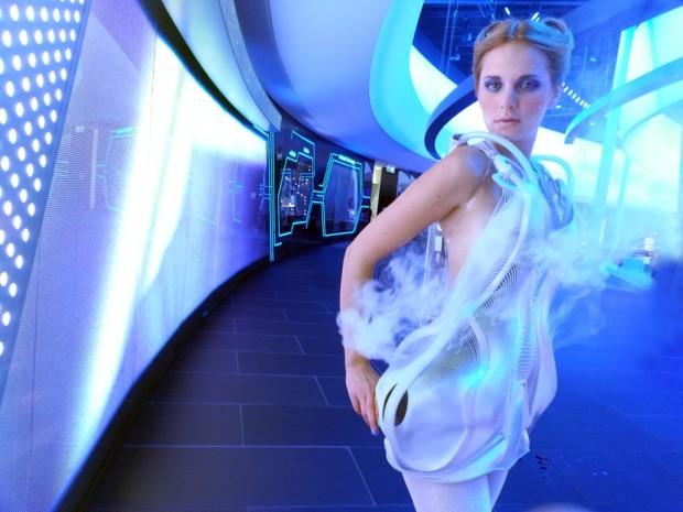
Anouk Wipprecht’s Smoke Dress
Back in 2014, Wipprecht launched a campaign to create the first crowdsourced 3D-printed dress, and followed this up with her Synapse Dress, partnering with Materialise, Niccolo Casas, and Intel to create a wearable that leverages the wearer’s own electrical currents for a fully immersive experience. The designer later combined 3D printing with virtual reality to create a collection of dresses for Audi, and worked with model and musician Viktoria Modesta to fabricate 3D-printed prosthetics for musical performance.
Now, the high-tech futurist designer is back with two new 3D-printed wearables that could be very useful in this time of social distancing, due to the continuing COVID-19 crisis: the Proximity Dresses, Robotic Personal Space Defenders.
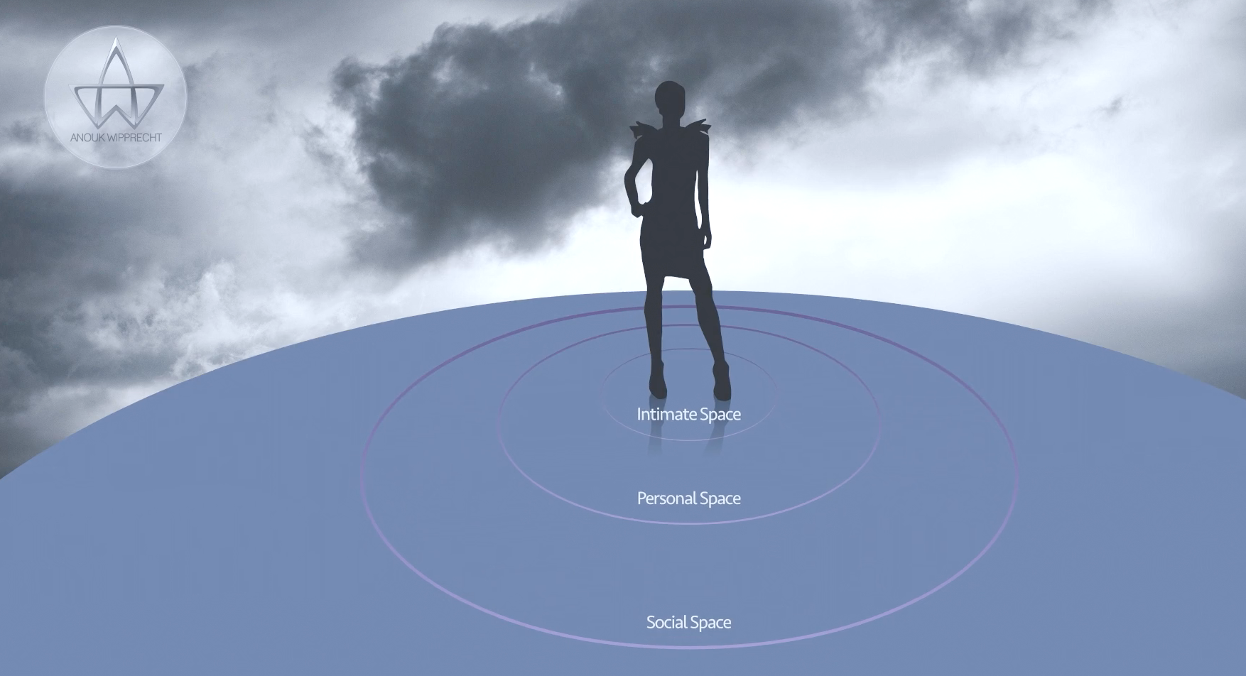
“Extending my research into proxemics and the body, I have fabricated two new dresses that create physical barriers when a person is detected in the immediate surroundings of the wearer,” Wipprecht said. “These twin dresses respond based on proximity and thermal sensors and indicates strangers within the intimate, personal, social and public space around the wearer.”
As with Wipprecht’s Smoke Dress and 3D-printed, robotic Spider Dress, which literally moves itself into an attack position if the embedded proximity biosensors detect that the wearer is uncomfortable, the design for these new dresses is based on Edward T. Hall’s Proxemics Theory. She explains that the theory defines “four spaces around the body,” each of which has its “own characteristic distances.”
Anouk Wipprecht’s 3D-Printed Spider Dress
“Whereas Hall had to measure the space between people using a wooden stick, I have been working since 2007 to translate these concepts into the digital domain, in order to measure the spaces between people up to a range of 25 feet,” she explained.
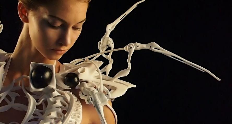
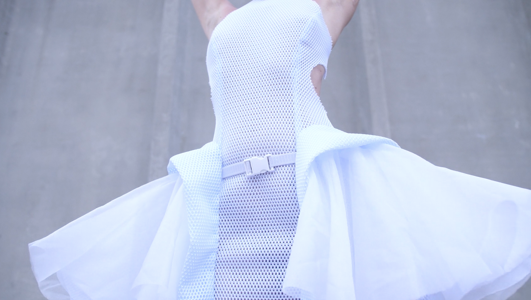
The Proximity Dresses use robotic, nylon 3D-printed hip mechanisms to extend when necessary. Additionally, they feature a transparent collar, 3D printed from clear resin, with some fancy sensors that offer noise-free distance readings.
Anouk Wipprecht’s Proximity Dress
These sensors use “high-output acoustic power combined with continuously variable gain, real-time background automatic calibration, real-time waveform signature analysis, and noise rejection algorithms. This holds true even in the presence of various acoustic or electrical noise sources, making it suitable for on-body use.”
By using the sensors, Wipprecht’s unique designs can invisibly trace their surroundings. Additionally, since the sensors don’t record any images or video, the dresses are not a threat to privacy, as nearby people remain anonymous.
“The Proximity Dress 2.0 is based on my 2012 prototype of this dress using hip mechanics create distance and a proximity sensor (ultrasonic rangefinder) for VW showcase during IAA, in Germany,” she concludes.
Check out the video below to see Wipprecht discuss her innovative, defensive Proximity Dress with Hyphen-Hub:
Discuss this story and other 3D printing topics at 3DPrintBoard.com or share your thoughts in the Facebook comments below.
Matt Denton has a 5-part series on YouTube of him building a D-O droid from Star Wars.
For the brains, Matt used an Arduino MKR-W1010, MKR Proto Shield, MKR-IMU inertial measurement shield, and MKR motor shield. For the sound board, he employed an Adafruit Audio FX Sound Board. For servos, he used Lynxmotion and Dynamixel.
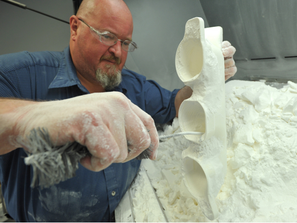
Researchers from Nanyang Technological University in Singapore wrote a paper, titled “Development of a Robotic System for Automated Decaking of 3D-Printed Parts,” about their work attempting to circumvent a significant bottleneck in 3D print post-processing. In powder bed AM processes, like HP’s Multi Jet Fusion (MJF), decaking consists of removing residual powder that sticks to the part once removed. This is mostly completed by human operators using brushes, and for AM technologies that can produce hundreds of parts in one batch, this obviously takes a long time. Manual labor like this is a significant cost component of powder bed fusion processes.
An operator manually removing powder (decaking) from a 3D printed part.
“Combining Deep Learning for 3D perception, smart mechanical design, motion planning, and force control for industrial robots, we developed a system that can automatically decake parts in a fast and efficient way. Through a series of decaking experiments performed on parts printed by a Multi Jet Fusion printer, we demonstrated the feasibility of robotic decaking for 3D-printing-based mass manufacturing,” the researchers wrote.
A classic robotic problem is bin-picking, which entails selecting and removing a part from a container. The NTU researchers determined that 3D perception, which “recognizes objects and determining their 3D poses in a working space,” would be important in building their bin-picking system. They also used a position-controlled manipulator as the baseline system to ensure compliant motion control.
The NTU team’s robotic system performs five general steps, starting with the bin-picking task, where a suction cup picks a caked part from the origin container. The underside is cleaned by rubbing it on a brush, then flipped over, and the other side is cleaned. The final step is placing the cleaned part into the destination container.
Proposed robotic system design for automated decaking.
Each step has its own difficulties; for instance, caked parts overlap and are hard to detect, as they’re mostly the same color as the powder, and the residual powder and the parts have different physical properties, which makes it hard to manipulate parts with a position-controlled industrial robot.
“We address these challenges by leveraging respectively (i) recent advances in Deep Learning for 2D/3D vision; and (ii) smart mechanical design and force control,” the team explained.
The next three steps – cleaning the part, flipping it, and cleaning the other side – are tricky due to “the control of the contacts” between the parts, the robot, and the brushing system. For this, the researchers used force control to “perform compliant actions.”
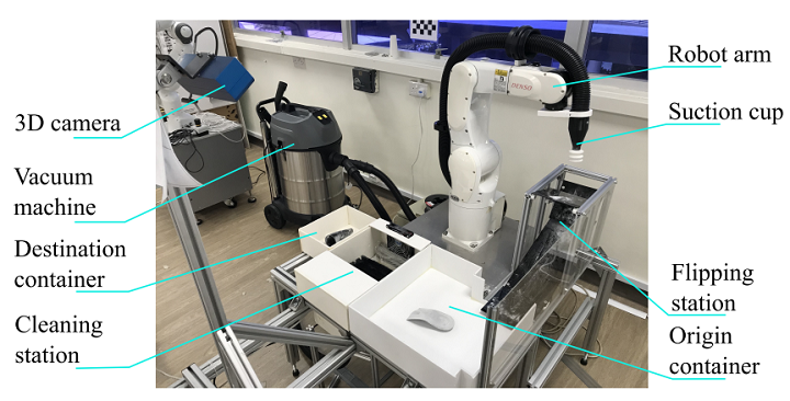
Their robotic platform made with off-the-shelf components:
1 Denso VS060: Six-axis industrial manipulator
1 ATI Gamma Force-Torque (F/T) sensor
1 Ensenso 3D camera N35-802-16-BL
1 suction system powered by a Karcher NT 70/2 vacuum machine
1 cleaning station
1 flipping station
The camera helps avoid collisions with the environment, objects, and the robot arm, and “to maximize the view angles.” A suction cup system was found to be most versatile, and they custom-designed it to generate high air flow rate and vacuum in order to recover recyclable powder, achieve sufficient force for lifting, and firmly hold the parts during brushing.
Cleaning station, comprised of a fan, a brush rack, and a vacuum outlet.
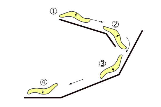
They chose a passive flipping station (no actuator required) to change part orientation. The part is dropped down from the top of the station, and moves along the guiding sliders. It’s flipped once it reaches the bottom, and is then ready to be picked by the robot arm.
Flipping station.
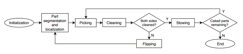
A state machine and a series of modules make up the software system. The machine chooses the right module to execute at the right time, and also picks the “most feasible part” for decaking in the sequence.
The software system’s state machine and modules perform perception and different types of action.
“The state machine has access to all essential information of the system, including types, poses, geometries and cleanliness, etc. of all objects detected in the scene. Each module can query this information to realize its behavior. As a result, this design is general and can be adapted to many more types of 3D-printed parts,” the researchers explained.
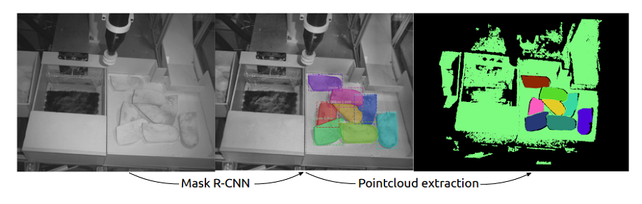
The modules have different tasks, like perception, which identifies and localizes visible objects. The first stage of this task uses a deep learning network to complete instance detection and segmentation, while the second uses a segmentation mask to extract each object’s 3D points and “estimate the object pose.”
Example of the object detection module based on Mask R-CNN. The estimated bounding boxes and part segmentations are depicted in different colors and labelled with the identification proposal and confidence. We reject detection with confidence lower than 95%.
“First, a deep neural network based on Mask R-CNN classifies the objects in the RGB image and performs instance segmentation, which provides pixel-wise object classification,” the researchers wrote.
Transfer learning was applied to the pre-trained model, so the network could classify a new class of object in the bin with a high detection rate.
“Second, pose estimation of the parts is done by estimating the bounding boxes and computing the centroids of the segmented pointclouds. The pointcloud of each object is refined (i.e. statistical outlier removal, normal smoothing, etc.) and used to verify if the object can be picked by suction (i.e. exposed surfaces must be larger than suction cup area).”
Picking and cleaning modules are made of multiple motion primitives, the first of which is picking, or suction-down. The robot picks parts with nearly flat, exposed surfaces by moving the suction cup over the part, and compliant force control tells it when to stop downward motion. It checks if the height the suction cup was stopped at matches the expected height, and then lifts the cup, while the system “constantly checks the force torque sensor” to make sure there isn’t a collision.
Cleaning motion primitives remove residual debris and powder from nearly flat 3D printed parts. The part is positioned over the brush rack, and compliant force control moves the robot until they make contact. In order to maintain contact between the part and the brushes, a hybrid position/force control scheme is used.
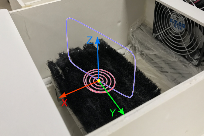
“The cleaning trajectories are planned following two patterns: spiral and rectircle,” the researchers explained. “While the spiral motion is well-suited for cleanning nearly flat surfaces, the rectircle motion aids with removing powder in concave areas.”
A combination of spiral and rectircle paths is used for cleaning motions. Spiral paths are in red. The yellow dot denotes the centroid of the parts at beginning of motion. Spiral paths are modified so they continue to circle the dot after reaching a maximum radius. The rectircle path is in blue, parameters include width, height, and direction in XY plan.
The team tested their system out using ten 3D printed shoe insoles. Its cleaning quality was evaluated by weighing the parts before and after cleaning, and the researchers reported the run time of the system in a realistic setting, compared to skilled human operators.
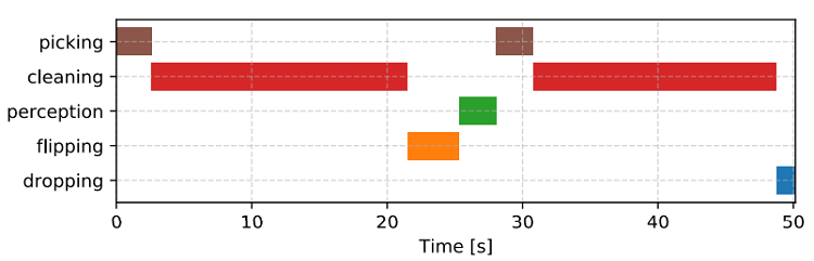
In terms of cleaning quality, the robotic system’s performance was nearly two times less, which “raised questions how task efficiency could be further improved.” Humans spent over 95% execution time on brushing, while the system performed brushing actions only 40% of execution time; this is due to a person’s “superior skills in performing sensing and dexterous manipulations.” But the cleaning quality was reduced when the brushing time was limited to 20 seconds, which could mean that the quality would improve by upgrading the cleaning station and “prolonging the brushing duration.”
Additionally, humans had more consistent results, as they are able to adjust their motions as needed. The researchers believe that adding a cleanliness evaluation module, complete with a second 3D camera, to their system would improve this.
Average time-line representation of actions used for cleaning.
“We noted that our robot ran at 50% max speed and all motions were planned online. Hence, the sytem performance could be further enhanced by optimizing these modules,” the team wrote. “Moreover, our perception module was running on a CPU, implementations of better computing hardware would thus improve the perception speed.”
While these results are mainly positive, the researchers plan to further validate the system by improving its end-effector design, optimizing task efficiency, and adapting it to work with more general 3D printed parts.
Discuss this and other 3D printing topics at 3DPrintBoard.com or share your thoughts below.
Each Friday is PiDay here at Adafruit! Be sure to check out our posts, tutorials and new Raspberry Pi related products. Adafruit has the largest and best selection of Raspberry Pi accessories and all the code & tutorials to get you up and running in no time!
GMAW-based technology is better for manufacturing metal parts with large dimensions than gas tungsten arc welding (GTAW) and plasma arc welding (PAW) methods because of its higher deposition rate. It’s important to achieve high internal quality of GMAW-printed parts, which is why it’s necessary to gain a better understanding of their microstructures – particularly when the component will be used in a load-bearing condition. This technology is consistently used in Vietnam because of its lower cost, so manufacturers should know all they can about the method in order to attain good results.
“Therefore, the objective of this study is to investigate the internal quality of thin-walled parts manufactured by the GMAW-based AM process. The results obtained in this study allow us to demonstrate the feasibility of using the GMAW robot for manufacturing or repairing/remanufacturing of metal components according to the AM principle,” the author wrote.
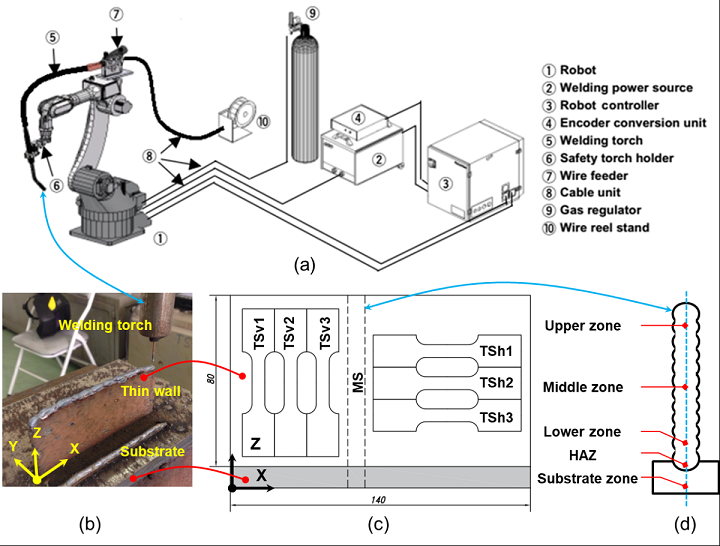
Figure 1. (a) Schema of the GMAW-based AM system, (b) built thin-walled sample, (c) positions for cutting the specimens, & (d) five zones for observing microstructures and measuring the hardness on a cut surface of the specimen.
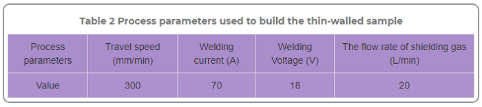
An industrial GMAW robot built a thin-walled component using the wire arc additive manufacturing (WAAM) process, out of mild steel copper-coated welding wire on a low-carbon steel substrate plate. The 6-axis robot used a welding torch to deposit layers from the substrate, and you can see the welding process parameters in the table below.
“The distance between the GMAW torch and the workpiece was 12 mm. The deposition was conducted at room temperature and without preheating the substrate,” Le explained. “Once the deposition of a welding layer was finished, the welding torch is retracted to the beginning point for the deposition of the next layer with a dwell time of 60 seconds. The dwell time used between two successive layers aims at cooling down the workpiece and transferring accumulated heat to the environment.”
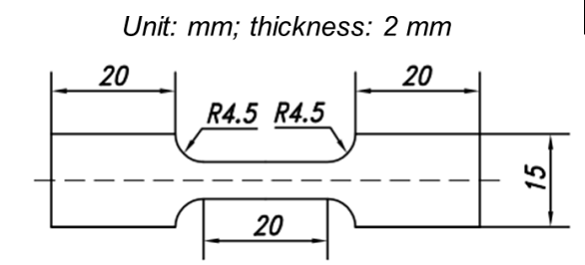
A wire-cut electrical discharge machining (EDM) machine was used to cut two groups of tensile specimens from the thin-walled sample, so that the author could measure the built material’s hardness, using a digital microhardness tester, get a closer look at its microstructures with an optical microscope, and test the tensile properties.
Figure 2 . Dimensions of the tensile specimen.
“Before cutting these specimens, two side surfaces of the built thin wall were machined to obtain an effective width of the built thin-walled materials,” Le wrote.
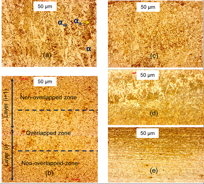
Figure 3. Microstructures of built materials observed in five zones: (a) upper zone, (b) middle zone, (c) lower zone, (d) heat-affected zone (HAZ), and (e) substrate zone.
The specimen’s microstructure was observed in five different zones. The upper zone, which features three types of ferrite grains and a high variation of thermal and high-cooling rates, has “lamellar structures with primary austenite dendrites” that distribute perpendicular to the substrate. The middle zone has two types of grains, and mostly features “the granular structure of ferrites with small regions of pearlites at grain boundaries.” The microstructures found in the lower zone, which has a slower cooling rate than the upper, are made of “equiaxed grains of ferrite, in which thin lamellae are distributed and coexisting with thin strips of pearlite.” These grains are finer than the ones in the middle zone, because the value of thermal shock is higher here.
In the heat-affected zone (HAZ), the microstructures transfrom from austenite to martensite, while the substrate zone features ferrite/perlite banded microstructures – the total opposite of the middle zone’s “homogenous distribution of phases.”
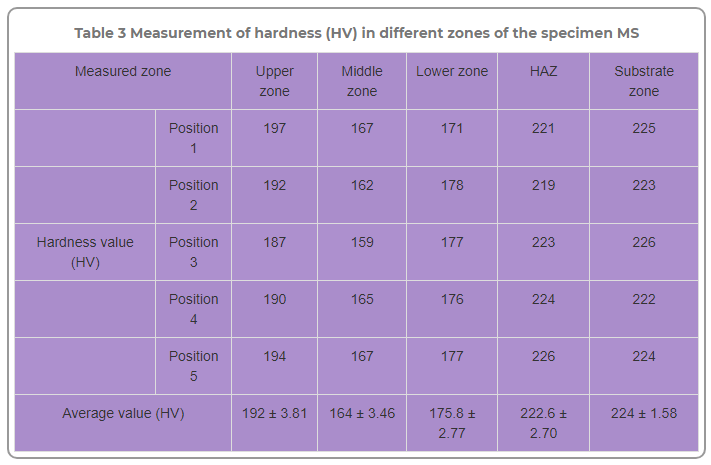
The above table shows the hardness (HV) measurement in the five zones. The upper zone had the highest HV, while the middle had the lowest, and the HAZ’s value was slightly lower than the substrate zone.
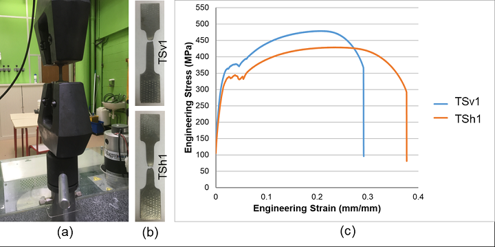
Specimens were tested on a tensile machine, and Le also figured the engineering strain-stress curves.
Figure 4 . Tensile tests with two specimens TSv1 and TSh1: (a) Installation of the specimen on the tensile test machine, (b) the broken specimens after the tensile tests, and (d) the engineering stress-strain curves.
“The hardness (ranged between 164±3.46 HV to 192±3.81 HV), yield strength (YS offset of 0.2% ranged from 340±2 to 349.67±1.53 ), and ultimate tensile strength (UTS ranged from 429±1 to 477±2 ) of the GMAW-based AM-built components were comparable to those of wrought mild steel,” he explained.
“There is also a significant difference in terms of YS and UTS between the vertical and horizontal specimens due to non-uniform microstructures of built materials. Moreover, the mechanical properties of the thin-walled component built by the GMAW-based AM process are comparable with those of parts manufactured by traditional processes such as forging and machining.”
This study found that the metal components built by GMAW-based robotic AM have “adequate and good mechanical properties for real applications.” Le concluded that it is feasible to use a GMAW robot to 3D print parts that can be used in industrial applications.
Discuss this research and other 3D printing topics at 3DPrintBoard.com or share your thoughts in the Facebook comments below.
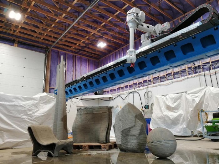
Dutch company Twente Additive Manufacturing B.V. (Twente AM, or TAM) is working to change the home building industry for the better, by challenging traditional construction methods through the use of automation and additive manufacturing. The company hasn’t been around that long, but had a big goal for its inaugural year in business – to create a large-scale 3D printer using an ABB 9-axis robot that is placed on a gantry-like structure for a large build footprint.
I’d say that Twente AM definitely succeeded in its mission. The structure supporting the conventional robot is able to move around enough so that it can build structures that are five meters high and ten meters long, which gives it a pretty impressive footprint of 391 m³….for comparison, a 6-axis robot can only complete a job with a 42 m³ footprint, but the rotational 9th axis that Twente AM added takes it the extra distance.
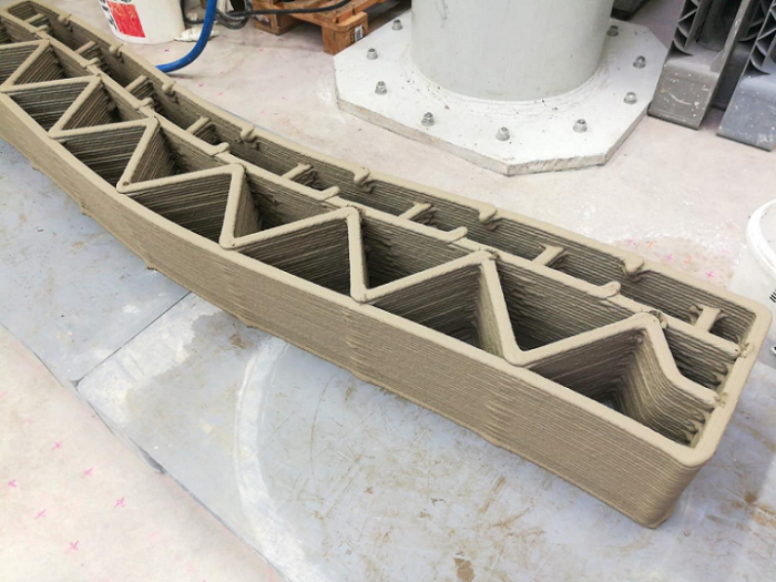
Ian Comishin, the President and Co-Founder of Twente Additive Manufacturing, explained in a press release that “The main role of this huge printer will be to create leave-in-place formwork for the construction of concrete homes to be built in British Columbia.”
The release goes on to explain that the extremely detailed prints its robotic AM system is capable of creating are made with a mortar material, which can rapidly cure within minutes to create artistic features and complex shapes that conventional methods of manufacturing just can’t complete. According to a video that the company released, parametric CAD/CAM software is directly connected to the large-scale printer, and makes these shapes through the use of algorithms.
The applications for Twente AM’s new 3D robotic 3D printing system include industrial architecture and building houses. That’s why the company took a pretty big risk in marketing its machine, only a few days after completing it, by live streaming its operation at the 40th Big5 international building and construction show in Dubai. Every day during the show, the team in Canada woke up at 2 am to get the machine started for the day. Check out the video to see the live 3D printing of Twente AM’s “record breaking concrete parts” below:
“Without hiding our failures, we gave them a taste of 3D concrete printing,” the video states.
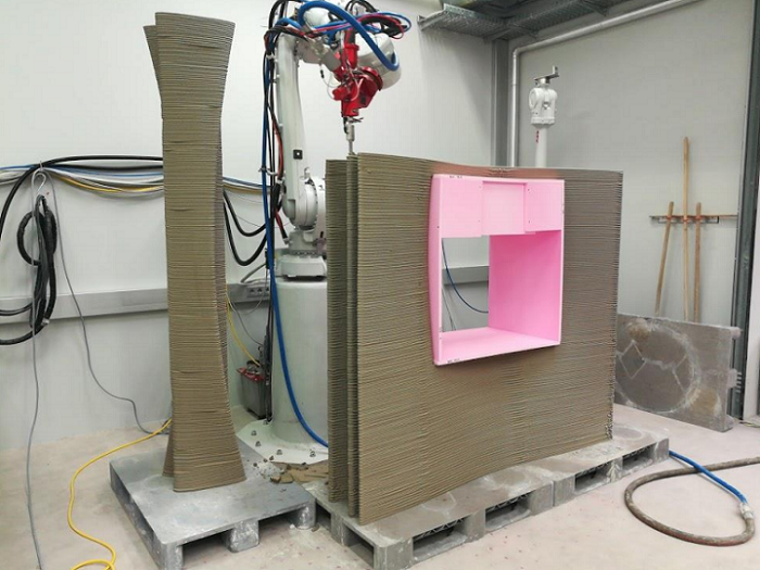
And there were indeed some failures, though as awed exhibition attendees could probably tell you, most of the complicated parts they fabricated were completed successfully. The team in Canada showed off the system’s fancy footwork with intricate designs, had a little fun in making an Arabic beach cabana, and also created some necessary parts for its ongoing project, such as a formwork for the loading dock.
The Twente AM team is obviously thrilled with the results of what I’d call a pretty big gamble, which is making many in the industry think harder about what 3D printing is capable of in the architecture field. But the company also recognizes that they wouldn’t be where they are today without the help of many colleagues – collaboration is key to making these kinds of big advances.
“We couldn’t be where we are now without collaborating with other talented members of the industry…We didn’t make this ourselves, this technology is at the very early adoption stage and working with the other companies and academic institutions throughout the Netherlands, Denmark, Austria, The UK and Canada who are taking on the challenge of solving 3D printing for home building is what Twente’s foundation is built upon,” said Tim Brodesser, head of R&D.
I’m pretty impressed with Twente AM’s work, and even more impressed by the fact that they live streamed the 3D printing process at a crowded exhibition not long after completing the system. It reminds me of something I witnessed two years ago in Illinois, by invitation of the US Army’s Engineer Research and Development Center’s Construction Engineering Research Laboratory (CERL).
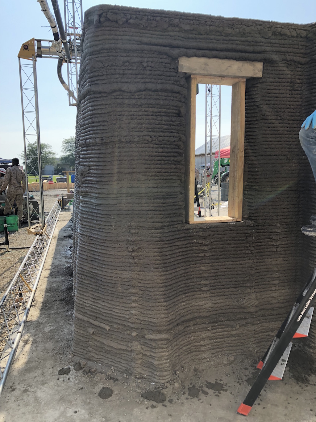
ACES demo (Image: Sarah Saunders for 3DPrint.com)
The team performed a live demonstration of its Automated Construction of Expeditionary Structures (ACES) technology by attempting to fabricate a 512 square foot barracks within 24 hours of continuous 3D printing; I say attempt because they did not succeed. But that’s what was so refreshing – we often hear a lot of hype about 3D printed construction, without much to back the claims up. So it’s really great to see teams that are brave enough to let others watch the process live, even if it may fail a time or two.
Discuss this story and other 3D printing topics at 3DPrintBoard.com or share your thoughts in the comments below.
(Images provided by Twente Additive Manufacturing)