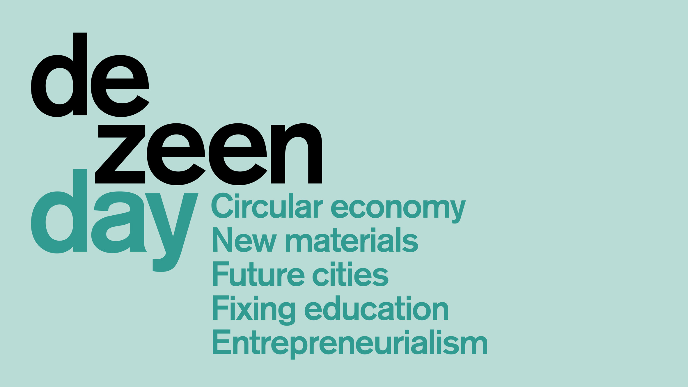
LiDar and its Applications Part 8 – Tourism

National Parks

Currently I am a tourist. It is fun to be in a different environment then your usual circumstances. It takes you out of patterns of monotony. When we travel our eyes are open to different lifestyles and we adapt new ideologies. It is great for people on an individual basis, but managing tourism on a large scale is still someone else’s job lol. So while a group of people in a specific site such as the Eiffel Tower may be prone to congestion if proper planning of infrastructure was not done. In particular, we will be analyzing LiDar and how we can utilize 3D data to plan tourism within parks.

National parks around the world are amazing sites that attract tourists nonstop. I plan on doing a large amount of trips to places like these soon, but I as a tourist am not aware of how precise my experience is. Park management involves the design and planning of how tourists like me will need to traverse the environment. The analysis of a large terrain gives us information on what is within our terrain. Elevation data, as well as land structural data, can be mapped in 3D. We can then create an ideal pathway for tourists to traverse through national parks. It would not be ideal for people to have log jams of movement within their environments. I recall when a time in high school quite vividly. My class and I were going on a trip to the Indiana Dunes. It is a great place to check out if you are in the Midwest of America and want to see some interesting wildlife as well as nature. The trail to get through the Indiana Dunes was extremely narrow and hard to traverse as a large group. We had to be in a single filed line the whole time throughout the trip. The state park, established in 1923 and opened in 1926, is about 3.4 square miles (8.8 square km) of shoreline, marshland, dunes, and forests near Chesterton.

Indiana Dunes

I imagine when this State Park was being established, there was no LiDar technology to help people design the State Park in an efficient manner. A lot of the paths were likely paved by physical effort. There was not a succinct manner in which the landscape data was known. If one is to build a new national park anywhere in the world now, we would be able to look at the environmental 3D data properly. This would then dictate how we could build paths and manage the resources of the particular landscape in question.

3D Point Cloud Terrain Data

With all this talk of nature, my inner hippie is growing. Seriously though, it is important for us to use technology to enable the betterment of our environment. This is essential and critical for the future and how we as humans will create our environment. This ranges from city planning to environmental planning, and this could include some of the interesting developments of planning civilization in space (many many many years away).

The post LiDar and its Applications Part 8 – Tourism appeared first on 3DPrint.com | The Voice of 3D Printing / Additive Manufacturing.

Interview with Riddhi Maharaj on 3D Printing Space Systems in Africa

NewSpace Logo

Riddhi Maharaj is a Materials Engineer at NewSpace Systems. In this interview, we discuss 3D printing with respect to Space components design, product development and Lean engineering.

Can you give a brief introduction of NewSpace Systems?

NewSpace Systems (NSS) is an advanced satellite component manufacturer predominantly focused on the operational SmallSat constellation market. Making use of our 30 plus years of experience in the space industry, our team specializes in high-reliability Attitude Control Systems and services such as contract manufacturing and technology commercialization. To date, our team has worked with nearly 50 customers, across 5 continents, and has a UK subsidiary and 6 international partners/resellers. Additionally, the NewSpace manufacturing capability currently comprises of a unique state-of-the-art facility on the African continent, boasting several ISO 14644-1, class 7, certified cleanrooms and technicians who have been accredited to European Space Agency standards (ECSS), to effectively support our international clients and their demanding missions.

A chemical engineer by training, I obtained my B.Sc Honours in 2013 and an M.Sc in Chemical Engineering in 2016. Currently, I am pursuing an M.Phil in Space Studies, part-time, through the University of Cape Town. While my formal title at NewSpace Systems is that of Materials Engineer, on a day to day basis I’m involved in several R&D projects, one of which was aimed at the development of metal additive manufacturing high-frequency Radio Frequency (RF) components.

From your experience, how important is 3D printing and Additive Manufacturing in product development and Lean Engineering?

3D printing is a constantly developing technology that plays an important role in rapid product development and lean engineering due to the nature of the process. By allowing for rapid prototyping of parts additive manufacturing is a critical stage in lean engineering product development.

Printer pictures MH3

3D printing is a technique that builds objects layer by layer using materials such as polymers, metals, and composites, offering unparalleled manufacturing flexibility. 3D printing relies on CAD software to print products and in so doing drastically reduces the amount of supply chain management. Due to the additive nature of the process, it allows for the manufacture of very complex components with a substantial reduction in manufacturing time, costs and material wastage which are key objectives in the lean engineering approach.

Additionally, AM provides the users with the flexibility to create complex part geometries that are difficult to build using traditional manufacturing methods. Parts can now be manufactured with intricate internal cavities and lattice structures that help reduce parts’ weight without compromising their mechanical performance. Furthermore, AM machines produce less scrap than traditional machines and allow for recycling of the metal powder alloys further reducing material wastage.

One of the major advantages, which further cements the importance of 3D printing in product development and lean engineering, is that 3D printing allows for the fabrications of monolithic parts. In the space industry where mass is a premium,3D printing allows for lighter more efficient products that can also be produced faster. This is a major benefit in space product development given the growing demands of the industry for rapid product R&D and delivery.

What significant role has 3D printing and Additive manufacturing played in NewSpace Systems?

NewSpace Systems as a lean engineering company has increasingly started to utilize 3D printing in our product development in the last couple of years. It is typically used for rapid prototyping of new products during the product development phase to develop marketing ‘mock-ups’ of our products,  and to manufacture complex test and product assembly jigs, to ensure that our products meet our stringent quality standards.

Space Components

Apart from that, NSS is actively involved in the development of a new product line that utilizes laser metal 3D printing in titanium and aluminum to produce high-frequency RF and microwave products. High-frequency RF products are used extensively in satellite communication payloads. These systems are highly complex and are both difficult and expensive to manufacture using traditional methods which also produce very heavy systems. Due to the geometric freedoms offered by metal 3D printing, it allows for extremely light-weight and even more complex and highly efficient RF systems to be manufactured faster.  This led to NSS incubating a spin-out company, LambdaG.

LambdaG is a technology company specializing in the design and manufacturing of advanced RF & microwave components. Their primary focus areas are microwave components and innovative antenna systems in space, defense, and aerospace domains. Together with NewSpace Systems (Industry partner), they offer bespoke and custom 3D-printed waveguide components for small satellites. This additive manufacturing solution allows for unparalleled design flexibility. Their primary solutions are, but not limited to antenna systems for Telemetry, tracking and control, payloads, feed chains, diplexers and filters, passive waveguide components and custom sub-assemblies. LambdaG’s goal is to advance RF and microwave connectivity within the space, aerospace and defense domains with the aid of material science and advanced manufacturing. LambdaG is currently developing several requirement-driven RF & microwave products from L- to Ka-band as innovative solutions to the growing satellite communication needs.

Space equipment

Has 3D printing become a key technology in Materials Engineering?

I think 3D printing has become a key technology across a lot of engineering disciplines, not just materials engineering. Through my experience with metal 3D printed materials, I have noticed active R&D in the production of metal alloys and a growing area of interest being metamaterials.


The post Interview with Riddhi Maharaj on 3D Printing Space Systems in Africa appeared first on 3DPrint.com | The Voice of 3D Printing / Additive Manufacturing.

Dezeen Day Recap

Dezeen Day

The first annual Dezeen Day conference, was definitely a sight to see and I will do my best to share my opinions on the day as a whole. I did not know what to expect going into the conference, but it seemed like it would be a fun time so I decided to go. It turned out to be an eye-opening and interesting experience.

Firstly I want it to be known that architects and designers think in such an interesting manner. I say this because you can see and hear the fascination they all have with life and building. They try to answer seemingly impossible questions. They design things through such innovative means. My brain was in pain throughout the day. It was not bad pain. It was the pain you get when learning something that is out of your comfort zone; it hurts now but you will feel amazing later. The way designers think allows them to have no fear of tackling large issues. The focus of this particular conference was on the Circular Economy and sustainability practices within design. In the design community, there is no one way to solve a problem. There are various ways to tackle an issue. Through the panel discussions and keynote speakers, we got a sense of how there are so many people working in different sectors of design to make this happen. I will reflect on a couple of major talks and discussion points from some of the panel conversations.

The first talk of the day was my favorite, and it had a lot of information packed within it. Paola Antonelli, the Senior Curator of the Department of Architecture & Design and the Director of R&D at MOMA, gave an interesting perspective to the audience. Her belief is that the understanding of humans and their likely extinction can lead to better resulting futures. What I deduced from this was that being aware of extinction leads us to be aware of the future generations and people we may be affecting. It is important for us to focus on future scenarios and think about how our actions can hurt others. This begs the question, “What can people do?”. The rest of the conference was aligned toward answering the question of what can people do to make effective change for the future within design. Paola also stated, “We want people to understand the complexity of the systems but not to be scared of them.” Designers are able to readily grasp design thinking and problem solving, but a variety of people outside the field may not be able to implore the same skills. This makes it important for design to help others outside of its community, and Dezeen Day also had a discussion on education reform. The conference was interwoven and facilitated elegantly. Each panel there was able to feed into one another.

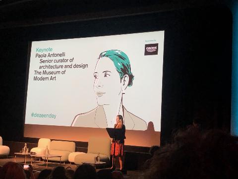
Paola Antonelli at Dezeen Day

There was a lot of information packed within this talk so I did my best to summarize a lot of her ideologies and main points of discussion. The talk had a focus on waiting for making things. Within the design community, ideas are a dime a dozen, but which ones are effective? Typically the ones that well mapped out and executed over time. This ties into her discussion about extinction. We are planning towards building better infrastructures to help humanity over time, and this takes a lot of diligence. This reflected the rest of the day in terms of discussions and panel conversations.

Throughout the discussion, Paola was highlighting the various art she curated for her Broken Nature Exhibition and the significance of each piece. Something of interest to me was the scientific lens that most of the pieces were taking. It lead to other discussion panels throughout the day focused on science, design, and architecture.

A final large takeaway of the talk was that anger could be a source of change.

The only way to live well is to be for others or amongst others. Anger could be a better engine to try and improve things in the future.

This mindset is interesting as it shows the raw emotion needed to drive change. Anger is a great motivator for change because when we are lukewarm, complacent and not very engaged with our surroundings, we have no reason to improve.

The rest of the conference was conducted through the lens of the initial talk. The discussion panels held were the following:

  • Panel discussion: post-plastic materials
  • Panel discussion: future cities
  • Keynote: Liam Young
  • Conversation: Designing for the circular economy
  • Panel discussion: entrepreneurs
  • Panel discussion: fixing education
  • Keynote: Dr. Alexandra Daisy Ginsberg

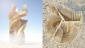
Work by Arthur Mamou-Mani

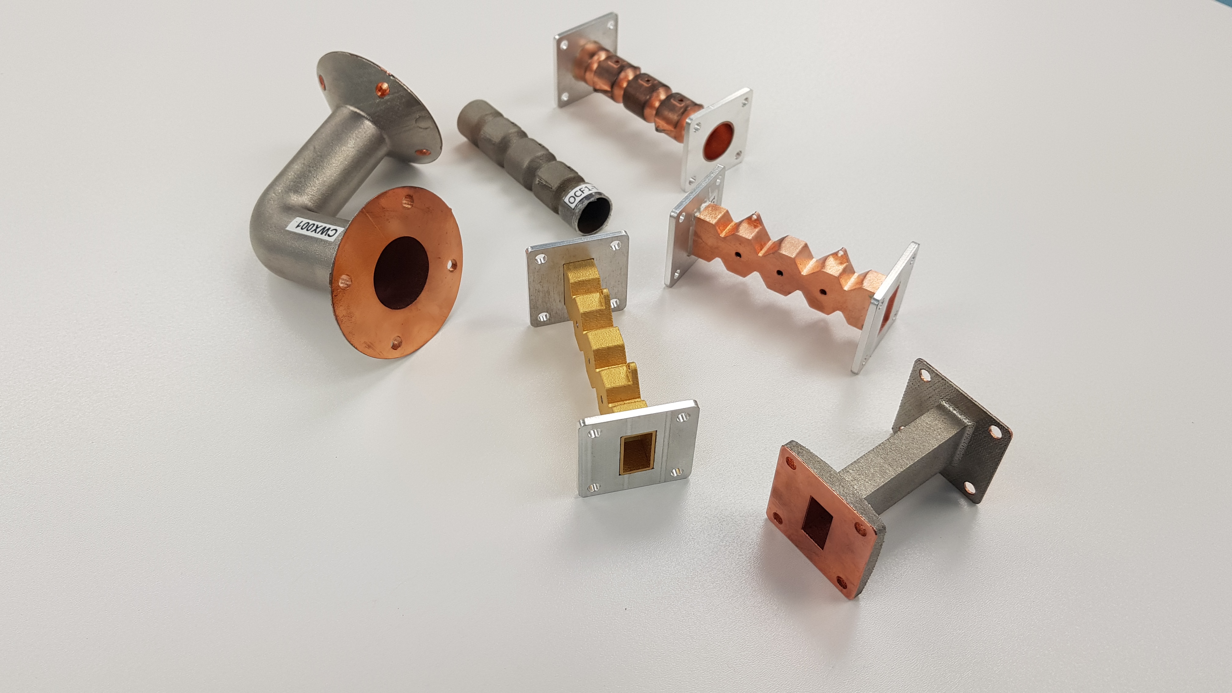
The ideals and conversations at the conference were outlined thoroughly with this introductory talk with Paola. I personally resonated well with the Panel Discussion for Post-Plastic Materials. The conversation was oriented towards the various ways we as humans can be innovative in the materials we are using. I was able to talk to some people from the discussion panel after their talk such as Natsai Audrey Chieza. She is a designer and founder of Faber Futures, and they create biologically inspired materials. After hearing the talk and seeing the work that these individuals are doing it opened me up to a critical lens of understanding with societal material usage. It also inspired me to think big in ways that seemed unfathomable. This was the result of listening to Arthur Mamou-Mani. Arthur is an architect and director of Mamou-Mani Architects. He also specializes in digital fabrication and advanced bioplastics. I was in awe by the extremely large structures he creates with 3D printing and the use of wood. I will be following up on his work later as well.

I also met some other people who helped with the conference. This included Stacie Woolsey who is a design graduate who created her own master’s course. We were able to have a fun chat before her actual panel discussion. She definitely is a great inspiration for young people who want to rid of the typical educational model. I will be discussing this thought process a bit more later.

There were a couple of conversations had about 3D printing and biomaterials that I will be discussing more in-depth because they require some more research. For the overall conference though, it was a good time. The staff was excellent, and the overall programming was extremely engaging. There was no moment without engagement talk wise. I am a reporter who mostly focuses on 3D printing, but after the conference, my eyes have opened up significantly to the importance of design practices. It was awesome to see people who were combining architecture, bioengineering, and design to build interesting things.

The post Dezeen Day Recap appeared first on 3DPrint.com | The Voice of 3D Printing / Additive Manufacturing.

LiDar and its Applications Part 4 – Agriculture

We have done a good background analysis on some of the building blocks of LiDar and how it can be applied to our environment so far. I am excited to talk about a field that is beyond my scope of understanding, but is essential to life. Let’s analyze how we use LiDar and 3D data for agricultural purposes.

Old school farming techniques are futile. When you have powerful machinery and technology such as drones and LiDar, a lot of the leg work is done for you. There are a number of major ways in which LiDar affects agriculture. Here are some of those affects:

  • Controlling or predicting Crop Yield
  • Crop Damage Analysis
  • Precision Agriculture
  • Land Mapping
  • Prevention of Soil Erosion
  • Land Segmentation
  • Crop and soil Analysis
  • Field Management

I will not drag you all as users with an in-depth overview of each sub category but I will focus on the following categories:

  • 3D Modeling
  • Precision Agriculture
  • Production Zones

Agriculture Mapping

3D modeling is a given when it comes to LiDar and the data it can capture. LiDar technology is vital for particularly modeling farmlands and it helps us to create accurate maps of natural resources around surrounding areas. This data allows a farmer to understand what type of terrain their farm is on. This allows for one to also understand the water catchment area of the land as well as the flow of erosion. A catchment area is a location in regions where water can collect from a higher area of land into a single body of water. These catchment areas are prone to drain water into other lower basins or into places such as a lake that have a closed body of water structure. This is all thanks to the data we collect from LiDar devices to map 3D terrain. Having these 3D models leads nicely into the next topic of interest.

Precision Agriculture

Precision agriculture is the preparation of a farm site with a goal towards improving the overall production capabilities of a site. This can lead to overall yields increasing tenfold within some land sites. Something to consider is the effect that precision agriculture may have on sustainability. If a farmer has knowledge about their land structure and how to best utilize it by building specific crops, one may have higher monetary returns as well as a better impact on the environment because the land is being used properly. Precision agriculture leads into our next topic of discussion, as this is a resultant from analyzing our land well.

LiDar is able to find specific areas of production that can lead to larger crop production and efficient usage of land. These production zones are specific to a piece of land and can be found by analyzing LiDar data. The data collected through this technology can help you select an area in a farm that is likely to flourish in terms of specific crops compared to other parts of the land. This is again a major factor in environmental sustainability and producing higher returns based on the land one has.

Discuss this article and more on the 3DPrintBoard or comment below to tell us what you think.

The post LiDar and its Applications Part 4 – Agriculture appeared first on 3DPrint.com | The Voice of 3D Printing / Additive Manufacturing.

Dezeen Day October 30th 2019

Ready for Take Off ?

I am beginning my journey of international conferences and events. I will have a nice miniature vacation with my trip to London this week. Outside of this brief respite, I have two conferences on my agenda. The first one will be Dezeen Day in London. I value the way knowledge can expand our knowledge and thought process and mindset. As a journalist, my main form of learning is through research and digging through archives. I was looking for various conferences for design and saw that this was in London. So I bought my ticket for London. Then I contacted some of the lovely staff at Dezeen Day and they arranged for me to attend the event! It is awesome being able to learn through being around others in professional fields. In this article, I will briefly explain what Dezeen Day is and a bit of why I am intrigued about the event.

Dezeen Day

So here is a shameless story about my childhood. Adults ask children this silly question of what do you want to be when you grow up. I, as a child, said I wanted to be an architect. Looking back at that I am far from this, but I do have some skills that would be under an architect’s tool belt. I am an avid drawer and I have a mathematically inclined brain. Design thinking is fun for me, and in general, I like building things. Dezeen Day is an international architecture, interiors, and design conference that will be held in London on October 30th. The conference will be trying to set the agenda for the global design community. This conference focuses on the concept of circular design, new materials, and educational resources. There is an emphasis on highlighting burgeoning talent from around the world. A keynote lecture will be given by Paola Antonelli, senior curator of architecture and design at The Museum of Modern Art in New York, and British multidisciplinary artist, Alexandra Daisy Ginsberg. 

BFI Southbank London

Dezeen Day will be held at the newly renovated BFI Southbank in London. This day will also have the Dezeen Awards winners’ party, where award winners from around the world will receive their trophies. Dezeen Awards is an annual awards program, that identifies the world’s best architecture, interiors and design, as well as the studios and the individual architects and designers producing great work. It is a great opportunity to see design and what people are doing in the field internationally.

I am excited to see what the day has in store for me. I’ll be getting a sneak peek of what is to come a couple of days before the actual conference. So be sure to tune into my own reflections and coverage of the event this week.

The post Dezeen Day October 30th 2019 appeared first on 3DPrint.com | The Voice of 3D Printing / Additive Manufacturing.

Coding for 3D Part 4: Rhino, Grasshopper and Weaverbird Setup

Rhino

After doing research on how we are going to attack this series with our toolbox of resources, we are setting up our environment for exploration. Setting up the build environment is simple enough, but it is vital. Even with our build environment, there are specific subtle things we need to do for our purposes of creation. We will go through some of these items in this article while highlighting some other integral parts.

Firstly we need to download Rhino for our modeling purposes. To do so check out this link for a free 90 day trial version of Rhino. After going through the download instructions, we can now use Rhino. When I first opened Rhino, frankly I was intimidated. I have used various 3D modeling environments and software, but Rhino’s interface is a lot to handle. No disrespect to Rhino as a package as it is great, but it seems to have a steep learning curve. It has various plugins and tools ready for your disposal. Something important to remember is that having various tools is often not the best route when building anything. This is a methodology I take in terms of technical project building as well as physical product manufacturing. My goal with Rhino is to build parametric designs through coding, so I have a precise route to learning. This allows me to get to the meat of what I want to do quickly. I would not benefit from a large overview of Rhino at this point. A lot of what Rhino has tool wise does look intriguing, but we will stay focused when using it. Otherwise our curiosity may let us stray from our path to getting things done.

Download Window for Rhinoceros

The biggest advantage of Rhino is the number of plugins available for it. These plugins are the essence of utility. We will focus on two plugins for Rhino in this series. The first plugin of interest to use is Grasshopper. Grasshopper is an algorithmic modeling plugin for Rhino. It uses a visual programming language vs. a typical text-based coding language. It also gives you the ability to reference geometrical objects from Rhino. The ability to create intriguing geometry quickly and with comparative ease is the main benefit of Grasshopper.

Grasshopper Build Environment

The second plugin of choice for us is Weaverbird. Weaverbird is a topology based modeler. It gives a designer the ability to make known subdivisions and transformation operators. This plugin allows us to automate subdivisions and reconstructing of shapes. It is a great plugin due to its ability to help in fabrication as well as rapid prototyping of ideas.

Weaverbird

Something I appreciate from Rhino is how extensive the program is from just looking at it briefly. Various software packages I have used are expansive, but Rhino seems to take things to a different level. The mind of an architect is very expansive, so their tool of choice needs to have various tools within its utility belt. I am excited to somewhat learn the mindset of an “architect” through operating in this program.

For the next installment of this series, we will try to make a simple 2D parametric design that can be extruded into 3D form. I realize the importance of 2D drawing and going to the 3D level as it makes product creation much easier. It flows better and it makes the ability to iterate more intuitive. So look out for that in our next article.

The post Coding for 3D Part 4: Rhino, Grasshopper and Weaverbird Setup appeared first on 3DPrint.com | The Voice of 3D Printing / Additive Manufacturing.

What is Metrology Part 23 – Error and Perception

Margin of Error

After a significant amount of time dedicated to this series, I have made some interesting insights.  When you think of metrology and measurement, humans need to understand that we are faulty at what we do. It is difficult to have true precision in measurement. We are prone to error and degrees of various errors. Secondly, no one human has the same perception as another. This leads to various incongruities in the physical realm. We can think in terms of optics, general psychology, and a vast number of phenomena. So how do we escape faulty perception and human error? Well, that seems impossible, but I am going to venture into these topics to show how they affect measurement and metrology as a whole.

Margin of error is a statistic that shows the amount of sampling error due to random occurrences. When we have a large margin of error, there lies less confidence in the data we collect. In reference to metrology, one can think of a scanning system as our measuring apparatus. When operated by a human, various things and random occurrences can affect the margin of error within a laser scan. This can include an unsteady hand when scanning an item. One could also have a slightly unclean lens that may cause distortion within a 3D scan. The movement of a target for 3D scanning may also affect this as well. There are a slew of items that may cause a 3D scan to contain large margins of error.

Act of Perception

Perception is how we organize, identify, and interpret sensory information in order to understand or represent our environment. Perception includes the ability for us to receive signals that go through our nervous system. This results in physical or chemical stimulation of our sensory systems. This allows us to interpret and understand the information we are bombarded with on a daily basis. Examples of this include how vision occurs through light interacting with our eyes, how we are able to use odor molecules to interpret smell, as well as our general ability to detect sound through pressure waves within the air. Perception is denoted by the receiver though. This means their learning, memory, expectation, and attention are vital for how the signals are interpreted.

I bring these things up as it shines a light on a key difference between machines and humans. Machines have less working experience, expectation, and learning compared to humans. Being able to consistently distinguish a watch in 3D form is natural for most humans, but a machine can be thrown off by slight variations in form. A machine automated process may have less error in terms of pure measurement, but the interpretation of the data is still a difficult task for a machine.

Issues of Perception and Metrology

Perception is typically thought of in two forms:

  • Processing an input that transforms into information such as shapes within the field of object recognition.
  • Processing that is interloped with an individual and their own concepts or knowledge. This includes various mechanisms that influence one’s perception such as attention.

Through laser scanning, an individual is able to collect data on a physical product. This data needs interpretation for it to have tangible value. A computer device is not readily able to do so. So metrology is a field based on our innate error and psychology as humans. But that does not mean the field is useless, as we humans have an innate desire to make things quantifiable.

The post What is Metrology Part 23 – Error and Perception appeared first on 3DPrint.com | The Voice of 3D Printing / Additive Manufacturing.

The Diamond Project

The Diamond Project

The Diamond Project is a business idea from Valerio Semeraro. He is an Italian born in Martina Franca, Puglia, Italy. He is a passionate, technical, and highly enthusiastic 3D printing artist. Martina 3D Printing is an Instagram page he started, and it lead to this particular project we are showcasing today. I think it is an interesting concept that with some assistance could scale.

The “Diamond” Project is trying to create a diamond capable of projecting holograms suspended in the air. 

We like to create objects that are unique in the world and different from anything we’ve seen before.We aspire to revolutionize the display of holograms with devices thanks to an application of 3D printing.

Diamond Project Prototype

Their Diamond wants to replace typical logos on the front bonnets of future cars. It will have a function similar to the Rolls-Royce statue and will highlight innovation, design, and technology. This design will give a futuristic look to cars as it will display a hologram on the hood. The technology they are using can also be readily applied to different mediums such as car headlights, audio speakers, gadgets for televisions, gadgets for telephones, lamps, advertising, and much more. It is a cool technology that is leveraging AR

Here is my opinion on the project. I think that the project is truly in its infancy and needs more guidance from seasoned business professionals. The concept is good and definitely a doable one technology-wise. I do not believe they have the bandwidth or business experience to grow this fully. I am helping them in the sense that I want to highlight them for this though: dogged persistence. I will say that Valerio and his team have been emailing me for months sending me different media as well as updates on their project. It shows that as an organization they will put in the work necessary to grow. They just need the right business counsel to grow exponentially.  

Valerio Semeraro

They are looking for some assistance in terms of company direction. Their intent is to create functional and futuristic prototypes starting from the holographic logos on the bonnets of cars. They are looking for someone to give them a hand to build their project. Their ideals of inventiveness came trough their Fablab origins. This idea won the Italian Microsoft award “SognatoriDigitali”. If this intrigues you and you want to help this project more contact them through email at diamond.project.hologram@gmail.com

The post The Diamond Project appeared first on 3DPrint.com | The Voice of 3D Printing / Additive Manufacturing.

What is Metrology Part 22 – 3D Translation and Rotation

3D Translation

3D translation and rotation is vital within a 3D environment. We have discussed the importance of this within metrology previously in CMM systems. Interfacing the physical world and digital world requires precise measurement coordinates. Within 3D environments, movement is vital. In particular, movement is our focus today. We will talk about how example code within Processing can help us interface the digital world and physical realm. How does one simulate the real world within a virtual space? VR and 3D build environments are critical. So what are the basics needed for measurement and calculating space in a digital field? Metrology systems and laser scanning help. Tracking movement in terms of translation within a coordinate system is vital. So how could we learn about the basics of all of this? Let’s look into Processing as our main digital coding tool. How does Processing compute translational movement? If one wants to understand coding in a 3D environment, it is highly recommended that you understand object oriented program. We will not do a deep dive into this today, but a lot of the operations we are doing are object oriented. The following code is how I will demonstrate movement within Processing:

size(640,360,P3D);

background(0);

lights();

pushMatrix();

translate(130, height/2, 0);

rotateY(1.25);

rotateX(-0.4);

noStroke();

box(100);

popMatrix();

pushMatrix();

translate(500, height*0.35, -200);

noFill();

stroke(255);

sphere(280);

popMatrix();

Processing Example Code

Let’s take a look at this line by line. The first line is dedicated to building the 3D environment. The background of this window is denoted by the color value 0 which corresponds to black. The lights() function allows us to use ambient light, directional light, and specular values within our environment. In this case we are using the default light structure. pushMatrix(), we have discussed before as a function that allows us to set our original matrix of data that will be manipulated later. Our manipulation will come in the form of translational and rotational forces implemented. translate(130, height/2, 0) manipulation in question. The rotateY() function is used to move the window towards a particular angle based on units from the Y-axis of our viewport. The rotateX() function is similar except it is rotating within the X-axis. noStroke() allows us to be free from bordered 3D image renderings. box(100) allows us to create a 3D box with a float dimension of 100 in the x-dimension. popMatrix() ends the manipulation of the original data set. We then are able to start a new data manipulation through translation with pushMatrix(). This time, we have used the following command to apply a translation: translate(500, height*0.35, -200). Instead of a box though, we created a sphere for rotation.

Planar Rotation

We have focused a lot on coding basics within this metrology series as a whole. Being able to have standardized measuring devices within our metrology equipment is key. Without such, we would lack tangibility. If a 3D environment cannot be built with a computer, there is no way to interpret the data from a 3D world that we interact with. Being able to set a coordinate based on the world around us is still a difficult task though. So how can we do this? It makes us question how most of the devices we use in metrology are able to accurately set values of measurements based on the real world. These set of questions are things I would further like to explore.

The post What is Metrology Part 22 – 3D Translation and Rotation appeared first on 3DPrint.com | The Voice of 3D Printing / Additive Manufacturing.

What is Metrology Part 21 – Getting Started with Processing

3D Environment Simulation in Processing

In the previous article, I showed the awesome coding framework of Processing. It is fun and interactive for anyone new to code. It makes learning a simple breeze, and it lines up a lot with the topics we have covered within this series thus far. These topics include image processing, 3D image rendering, 3D scanning, pixelation, image restoration, and a slew of other applications. With this article, I will show you how to get started with this program.

To get started, one should visit Processing and their website. From there, you can go to their downloads page and find the corresponding installation package that is right for your system. The package for Processing will be found in a zip file in your downloads section once it is unpacked from the website. Within this download package you will click through it to find an icon that says processing. Once you click this your computer will prompt you to extract the file into a different location. After this you may now use Processing.

Processing Sketchbook

Once you open Processing you will notice the sketchbook and developing environment. That is where all of the code will be run and executed. In order to code within this environment, one needs to understand how to manipulate movement and vision within the 2D realm first before moving to 3D. I think having a solid foundation within 2D leads to better 3D thinking because geometry naturally flows this way. Processing is object oriented and it utilizes rotational and translational commands to make interesting visuals. The majority of commands used in 2D will be applicable to 3D. Processing fortunately has a 2D transformation tutorial online that is a great starting point for explaining the capabilities. Below is a snippet of code that is from the processing site and it has comments on what these lines mean. 


void setup(){

  size(200,200); //size of the window

  background(255); //color value of the background

  noStroke(); //disables the border drawing of the stroke

  //draw the original position in gray

  fill(192); //Sets the color used to fill shapes.

  rect(20, 20, 40, 40); //draws the rectangle with these dimensions  

  //draw a translucent blue rectangle by translating the grid

  fill(0, 0, 255, 128); //fills a rectangle with the blue color

  pushMatrix(); // Pushes the current transformation matrix onto the matrix stack.

  translate(60, 80); //translates the original rectangle 60 units right and 80 units down

  rect(20, 20, 40, 40); //draws the location of the translated data of the original matrix

  popMatrix(); //  Pops the current transformation matrix off the matrix stack.

}

To initialize a build environment in Processing, one needs to setup the environment. Setup calls a function for a viewport to see the digital code. The window size is denoted as well as the background color. The noStroke() function disables Processing and its automatic border drawing for images. 

Executed Script in Processing

Then a fill function is used to color any shape after this definition to be this color. To set the dimensions of our box, we used the rect() function. Then we wanted to create a new blue rectangle so we applied the fill function again but with different values. After this we want to apply translations to the original matrix data we had for the rectangle in terms of location. The pushMatrix() command essentially opens up a loop of interaction within our code to allow us to independently control objects within our environment.  Then we are able to apply the translate function to our original matrix data. In this case we translated the data to the right 60 units and down 80 units. Then we ended this cycle by applying the command popMatrix(). 

3D Wireframe Processing

Whenever one wants to code, it is good practice to know what every command or function within your code means. Without knowledge of this, you are going to become a copy and paste coder who does not understand the nuances within their own code. It also will take you a bit more time to go through programming tutorials when you stop to learn exactly what everything means, but at a certain point you will gain a greater overall scope of the tools you have at your disposal. With this basic code example, we can expand our skills and apply this in 3D. In the next article, I will show how to do so. 

The post What is Metrology Part 21 – Getting Started with Processing appeared first on 3DPrint.com | The Voice of 3D Printing / Additive Manufacturing.