
The US Air Force is using Senvol’s data-driven machine learning software for additive manufacturing (AM), to enable the production of large-scale aerospace parts using multi-laser 3D printing technology. Utilizing an EOS powder bed fusion (LPBF) 3D printer, the program is focused on developing baseline mechanical properties and design allowables, to optimize the production of end-use […]
Reducing 3D Printing Collisions with Toolpath Optimization Methodology
 While many industries are using 3D printing to manufacture products, the technology has not been largely adopted in large-scale production. According to researchers from the University of Arkansas Department of Industrial Engineering, this is mainly due to cycle time. However, while it’s possible to print different parts of one object at the same time thanks to multiple collaborating printheads, this isn’t yet widely supported by research. Hieu Bui, Harry A. Pierson, Sarah G. Nurre, and Kelly M. Sullivan published a paper, titled “Tool Path Planning Optimization for Multi-Tool Additive Manufacturing,” that lays out their proposed toolpath optimization methodology.
The abstract states, “The objectives are to create a collision-free infill toolpath for each printhead while maintaining the mechanical performance and geometric accuracy of the printed object. The methodology utilizes the combination of tabu search and novel collision detection and resolution algorithms, TS-CCR. The performance of the TS-CCR is analyzed and compared with the current industry standard.”
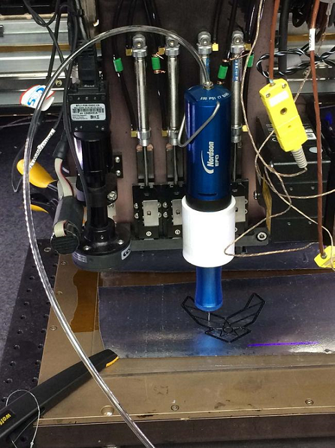
The FFF 3D printing process is limited by how fast the printhead is able to move, melt, and dispense filament. The parallel processing method, which lets multiple toolheads work together at the same time to fabricate different parts of the same object, is used by the Autodesk Netfabb software function for Project Escher 3D printers. This can obviously speed up printing time, but also increases the chance for collisions.
Netfabb uses an algorithm to make sure that all the printheads are synchronized, so they can’t collide with each other.
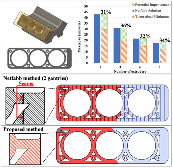
Summary of the result from the case study of Netfabb’s performance and toolpath illustrations (30% infill) of the Netfabb method and proposed method.
The goal of this methodology is to consider collision constraints for 2-gantry 3D printers, while also minimizing the single layer makespan (printing time).
“The shortcomings of current methods, the lack of published research on concurrent FFF, and the need for an alternative path-planning method for multi-gantry FFF 3D printers inspired the development of a new method,” the researchers explained. “Although the multi-gantry system is one of several kinematic configurations of concurrent FFF 3D printing, increased understanding it can provide insights into the development of generalized multi-tool path planning problems for AM processes.”
A Tabu Search (TS) heuristic (practical method of problem solving), which uses a memory mechanism to store information to help guide future searches, was used to optimize the single layer makespan in the methodology by adjusting the toolpath for the infill. The TS incorporates three main operators:
- The local swap operator swaps two raster segments printed by the same printhead to reduce the rapid movement distance
- The global swap operator exchanges two raster segments that have been printed from different printheads
- The rebalancing operator allocates one raster segment from the printhead with a higher makespan to the other printhead
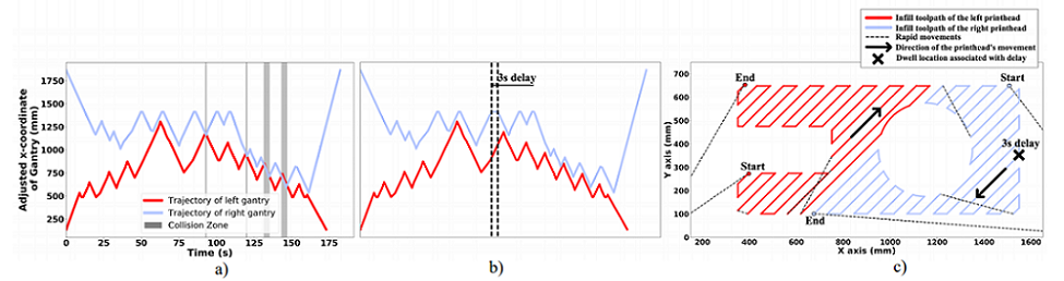
a) trajectory plot produced by the collision checking algorithm (tested layer A with 1% infill) showing 4 possible collisions (i.e. vertical gray bars); b) trajectory plot after adding 3 seconds’ delay to resolve the first collision (note that it also resolves the following collisions); c) toolpath representations of solution in 2b. The arrows indicate the two gantries are moving in the opposite directions toward each other when printing the associated raster segments. By adding 3 seconds delay at the dwell location, the two gantries synchronized and avoided the potential collision.
“At the beginning of the algorithm, with a randomized initial solution list, the global swap operator is favored. Due to the high degree of randomization of the sequence and the high number of collisions, adding delays might not be able to resolve the collisions, in which case the two gantries will work in sequential order. The goal is to segment the appropriate raster segments into two groups, one group for each printhead. The number of collisions begins to decrease as a result. Later on, the local swap slowly becomes more attractive.”
Two complementary algorithms work with the TS: a collision checking algorithm, which detects any potential collisions, and a collision response algorithm, which finds points in the toolpaths where a collision can be avoided by adding a delay.
The researchers explained, “An efficient collision checking algorithm should be able to quickly detect the collisions for a large number of raster segments and identify the corresponding movements that caused them. By utilizing a unique characteristic of the multi-gantry FFF machine, the process of identifying the collisions can be simplified. In such configuration, the collisions happen every time the gantries collide in the x-direction. In other words, a collision happens when the two gantries share the same workspace at any moment in time. A safety distance between two gantries was added when constructing the trajectory plot as a way to keep the gantries away from each other even though the collision is detected.”
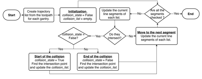
Flowchart of collision checking algorithm
“The motivation of the collision response algorithm is to identify an opportunity for resolving the collision by adding a delay. It is worth mentioning that each vertex on the trajectory plot represents a potential place to insert the delay.”
This algorithm has 4 steps, the first being to identify a set of line segments that are associated with the first collision, and then figuring out whether a delay could fix the collision. Third, the delay is inserted and all future trajectory segments are adjusted, and finally, you move up in time to find the next collision; then, lather, rinse, repeat until the collisions are gone.
The team’s methodology for avoiding 3D printing collisions was thus named Tabu Search with collision checking and response, or TS-CCR.
“The TS-CCR outputs a solution represented as a combined list of sequences of raster segments that must be printed for each printhead,” the researchers wrote. “To get the infill makespan of the solution, an infill toolpath for each printhead is constructed from the aforementioned solution. The collision-checking algorithm then searches for any potential collisions and passes the information to the collision-response algorithm, which introduces delays in order to prevent potential collisions.”
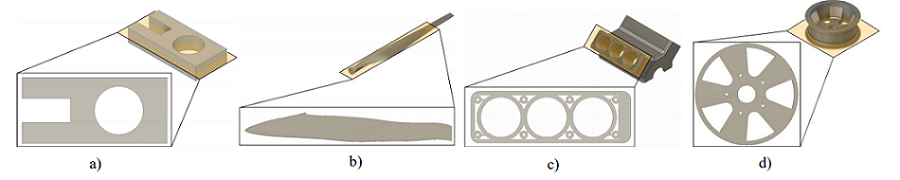
a) tested layer A; b) turbine blade layer; c) engine block layer; d) wheel rim layer. The wheel rim layer is considered a special case since Netfabb did not produce a solution.
To test the TS-CCR’s performance, the team chose four objects, then sliced a selected layer of 0.3 mm from each and computed the results from the theoretical minimum makespan, slicing the layer with the Netfabb Multi-Gantry FFF Engine and the 2018.1.0 Escher plugin, and the TS-CCR.
They collected information, such as build volume and print speed, about the multi gantry 3D printer from the Titan Cronus profile in Netfabb.
“For the TS heuristic, the value for the size of the candidate list and tabu tenure were chosen as 10 and 4, respectively. The algorithm terminates if it has been running for 2 minutes since the last improvement,” the researchers explained.
Then, they compared the makespan for three solutions – the theoretical minimum, proposed methodology, and Netfabb for 2 printheads – in a trajectory plot, which shows how the algorithms performed. 55 seconds of delays were added at different points, but because most of these were introduced in the printhead with a shorter makespan, only three total seconds were added to the overall makespan. This plot also shows how important the rebalancing operator is in TS – the gantries completed their work at almost the same time.

Trajectory plot of the result obtained from the TS-CCR (engine block layer with 30% infill). The printing time of the two gantries are 1272 and 1269 seconds, respectively.
“The performance of the methodology varies depending on the complexity of the layer. It can reduce the makespan of the “tested layer A” by 14.48% as compared to Netfabb, while the improvement reduces to 10.18% for the “engine block” layer. Since only one printhead is utilized to print the perimeter shells, the time spent on printing the shells likely offsets the improvement of the proposed methodology for any complex layer. Since this work focuses on only optimizing the infill, the method of allowing multiple printheads to print the perimeter shell at the same time can be implemented to reduce the makespan further,” the researchers wrote.
While there are only about 11 minutes of makespan reduction for the tested layer over the single printhead, this kind of improvement can accumulate across all layers and reduce the overall time.

a) makespan comparison for 3 layers (tested layer A, engine block, turbine blade) at 30% infill, where the proposed method can yield a solution with a shorter makespan than the solution obtained from Netfabb; b) makespan comparison for the “wheel rim” layer, where Netfabb did not produce a solution. The result from the methodology is compared to the makespan if the same layer is printed by the single printhead and the theoretical minimum.
The team’s proposed TS-CCR methodology can solve major issues of using multi-gantry FFF 3D printing, such as carefully planning to avoid mutual collisions while also not compromising the strength of the final print.
Discuss this and other 3D printing topics at 3DPrintBoard.com or share your thoughts below.
The post Reducing 3D Printing Collisions with Toolpath Optimization Methodology appeared first on 3DPrint.com | The Voice of 3D Printing / Additive Manufacturing.
AFRL and University Partners Used 3D Printed Composite Materials to Make Structural Parts
 The Air Force Research Laboratory (AFRL), located at Wright-Patterson Air Force Base (WPAFB) near my hometown of Dayton, Ohio, has long been interested in using 3D printing and composite materials for the purposes of aerospace applications. Last year, AFRL’s Composites Branch at the Materials and Manufacturing Directorate partnered up with researchers from the University of Arkansas, the University of Miami in Florida, Louisiana Tech University, and the University of Texas at El Paso (UTEP) to work on advancing 3D printable composite materials.
The Composites Branch works on the research and development of organic and ceramic matrix composite technologies for legacy, developmental, and future Air Force system components. Together with its university partners, the AFRL branch demonstrated 3D printed composite materials, made from a combination of carbon fiber and epoxy, which had been successfully fabricated and used to make structural parts on both air and space craft. The results of this 3D printed composite material effort will soon be published in a special issue of the Journal of Experimental Mechanics that’s dedicated to the mechanics of 3D printed materials.
Dr. Jeffery Baur, leader of the Composite Performance Research Team, said, “The potential to quickly print high-strength composite parts and fixtures for the warfighter could be a tremendous asset both in the field and for accelerating weapon system development.”
 Composite materials are made up of two, or sometimes more, constituent materials that have very different chemical or physical properties. When combined, these components produce a new material that has characteristics which are different from the originals. The individual components that make up the composite will remain distinctly separated within the final material structure.
When compared to the more low-quality polymers that are typically used in 3D printers, the composite materials demonstrated by AFRL and its partners are the same type that are already being used to make Air Force system components. These materials are very strong, while also lightweight, and have higher thermal and environmental durability than most.
Most traditional epoxy and carbon fiber composites are made by layering carbon fiber sheets, coated with epoxy resin, on top of each other. Then, the whole thing is cooked for hours in a costly pressure cooker to finish. The major downside to this method is that it’s more difficult to create parts that have complex shapes when sheets are being used.
This is where additive manufacturing comes in. Composite materials that are 3D printed are able to create parts with those complex shapes, and additionally don’t require the use of long heating cycles or expensive pressure cookers. On a materials level, there aren’t a whole lot of downsides to using composites for the purposes of producing, assembling, or repairing parts for the Air Force, whether at the depot or out in the field.

Military branches in other countries are also seeing the benefit of 3D printable composite materials. For example, engineers in India are manufacturing complex core structures using the composite 3D printing process; when combined with top and bottom face sheets, these structures will create lightweight sandwich structures that have properties tailored specifically to, as AFRL put it, “the physical forces that need to be carried.”
Conventionally fabricated sandwich structures use the same core geometries over the entire area of an aircraft skin, but a 3D printed version would be able to stand up under heavier forces when necessary, while also remaining lightweight in other parts of the skin.
Discuss this story and other 3D printing topics at 3DPrintBoard.com or share your thoughts in the Facebook comments below.
[Source: Dayton Daily News]
AFRL and U.S. universities create 3D printable epoxy/carbon fiber composites for aircraft parts
The U.S Air Force Research Laboratory (AFRL) has collaborated with researchers from the University of Arkansas, the University of Miami, Louisiana Tech University and the University of Texas at El Paso to develop 3D printable epoxy/carbon fiber composites. Such materials are set to be used in the production of 3D printed structural parts on air and […]
Ambots, collaborative mobile 3D printers, usher in new era of digital factory
Ambots, an Arkansas-based 3D printing technology and assembly provider, has developed a class of mobile robots, which the founders say will initiate a new kind of digital factory. Wenchao Zhou, co-founder of Ambots, said, “Right now, we’re trying to figure out the minimum set of robots needed for a generic digital factory.” Mobile 3D printer […]
University of Arkansas: Research Group Delegates 3D Printing Duties to Their Swarm of Robots
“Individuality is what drives humans.” – Wenchao Zhou
3D printing and robotics have been a match for decades, and they continue to have a future together in manufacturing. When it comes to the AMBOT project Wenchao Zhou, Lucas Marques and Austin Williams are creating, however, it’s less of a one-on-one deal and more of a swarm. Or perhaps you could consider it an entire construction crew as they complete intricate production tasks, perform assembly of items, use tools like screwdrivers and sharp instruments, weld, and even do some 3D printing of their own.
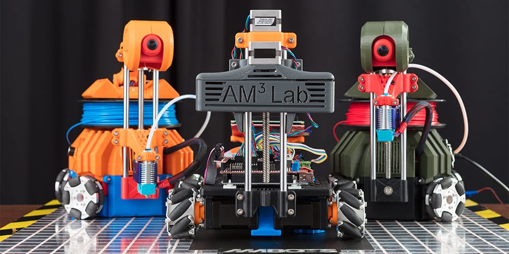
“Right now, we’re trying to figure out the minimum set of robots needed for a generic digital factory,” says Zhou, a professor of mechanical engineering at University of Arkansas and director of the AM3 Lab. There, Zhou, Marques, and Williams are cloistered away in an austere laboratory creating the future of 3D printing technology.
The team of young researchers understands the obvious potential for 3D printing in manufacturing. The benefits are immediately enticing, especially to larger companies and organizations around the world with vast resources like GE and NASA, all willing to jump in and try new brilliant new technology, along with encouraging their own scientists, researchers, engineers, interns, and collaborating students around the world. Greater speed in turnaround time of creating parts, the ability to design and manufacture all in one lab without a middleman, exponentially greater affordability in some cases, and rapid prototyping capabilities make 3D printing impossible to ignore.
But there are so many obstacles still too, and this is what the AM3 Lab wants to work past, creating even better options in scalability and speed, and streamline issues such as support structures that cause greater expense, inhibit efficiency, and are more inconvenient to deal with overall. This is magnified greatly when parts are being made for something massive like a military plane.

Wenchao Zhou
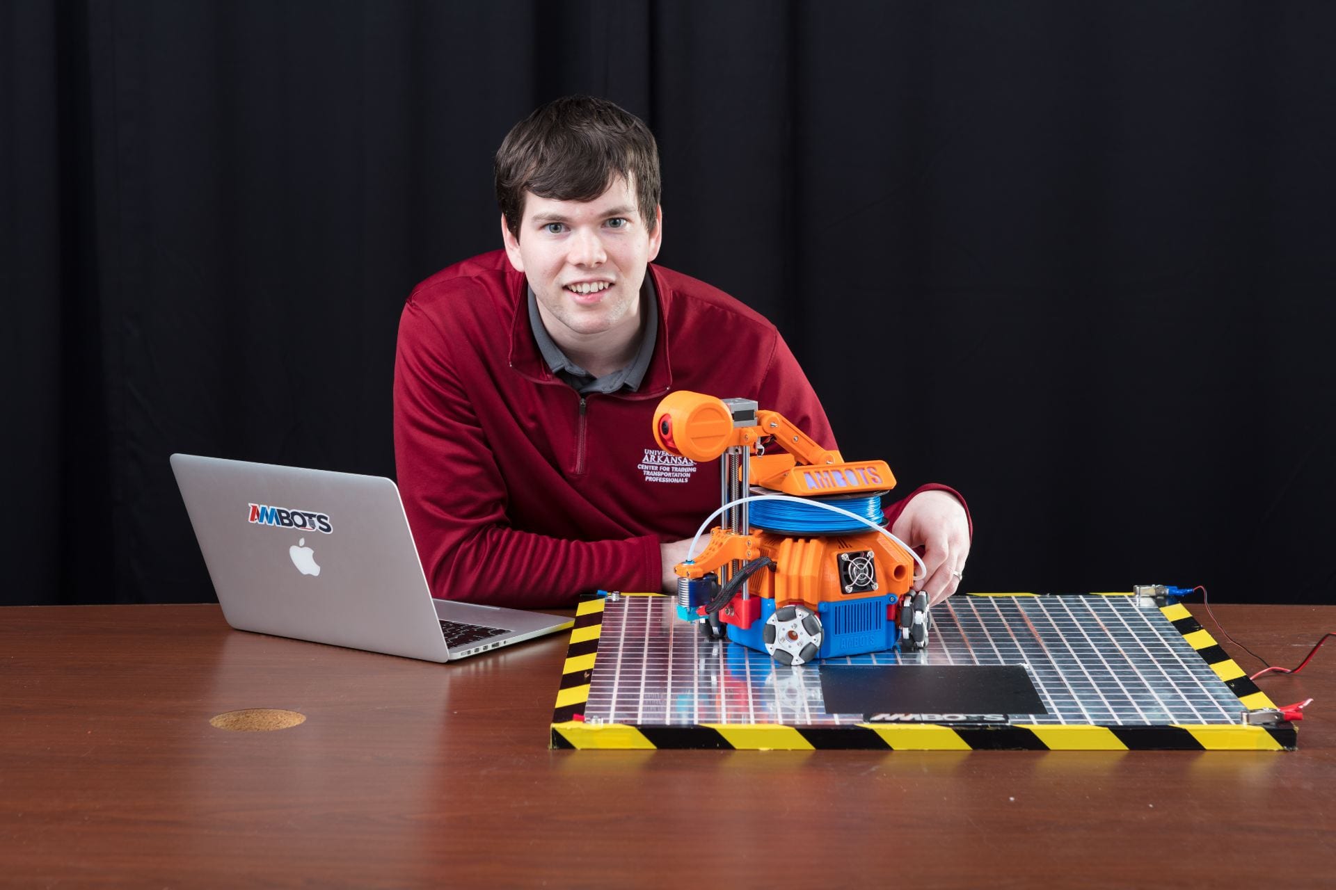
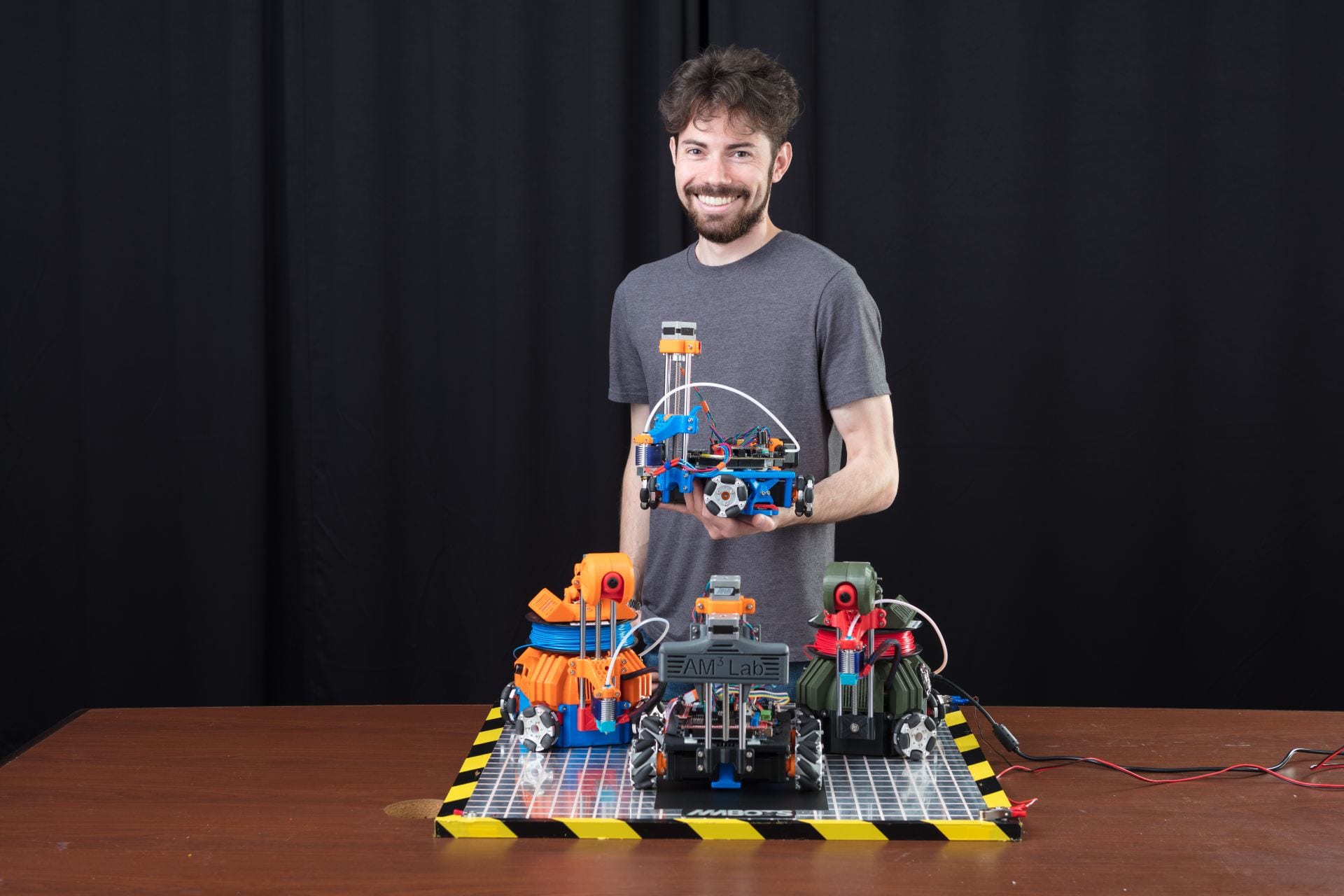
Their solution goes far beyond ‘thinking outside the box,’ as they built an autonomous (and mobile) 3D printing ‘vehicle’ able to work with a group of large and untold numbers so far. This is where the swarm comes in, as the robots come together like a crew to manufacture a plane or a house. The key, from Zhou’s point of view is to allow each piece to be completely customized.
AMBOTS was founded this year by Zhou, Marques, and Williams, and their goal is to create a mini-factory at Arkansas Research and Technology Park—and fill it with thousands of robots. Zhou has already worked in 3D printing for over ten years, with ongoing projects in more rudimentary robotics, progressing into what are now more sophisticated printbots, or AMBOTS.
Each robot is 80 percent 3D printed. The team had some fun with their features, creating colorful, different styles—each one with a unibody featuring the following:
- Chassis with a control panel
- Electrical circuits controlling the parts
- Wheels with rubber pads
- The Z stage, moving the tool head up and down
Austin Williams
Lucas Marques
Each printbot each has a printer, filament spool, and an extruder.
“Manufacturing technology is a symbol of the level of human civilization,” says Zhou. “For most of human history, craftsmen customized products, be it clothes, shoes or even weapons. But today, everything is mass produced, due to cost. We want to change this. We want to build generalized, autonomous factories that can produce anything for anyone, on demand and inexpensively.”
What do you think of this news? Let us know your thoughts; join the discussion of this and other 3D printing topics at 3DPrintBoard.com.
3D Printing Industry review of the year October 2018
For the 3D printing industry, October 2018 was a month of progress and milestones. This month brought an extinct species back to life, and Apple’s 3D printer closer to birth. Flying higher with 3D printing October was a big month for GE Additive. The company announced a landmark event in the history of aviation and […]
Thesis Focuses on Using Cooperative 3D Printing with Robots to Improve the Technology’s Scalability
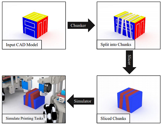
Illustration of the slicing strategy for cooperative 3D printing.
Obviously, the size of your 3D print is limited to the size of your 3D printer…you wouldn’t try and 3D print a building, no matter how small, using a desktop system, right? Jace J. McPherson from the University of Arkansas put it more exactly in the honor’s thesis he wrote and submitted for his Bachelor’s degree in Computer Science and Computer Engineering:
“More specifically, an object cannot be printed if it is wider than the full horizontal movement range of an extrusion nozzle or if it is taller than the maximum height of the extrusion nozzle above the printing surface (i.e., the “print bed”).”
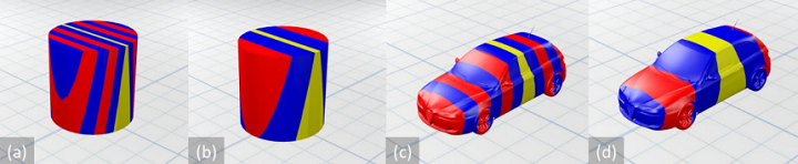
Chunker results with a cylinder and a car model.
According to McPherson’s thesis, titled “A Scalable, Chunk-based Slicer for Cooperative 3D Printing,” print jobs’ size limitations can hinder the technology’s goal of being “fully dynamic.” In the thesis, he focused on the issue of 3D printer scalability – limited by print bed size and use of a single printhead – and lack of manufacturing automation, and the idea of cooperative 3D printing, and a new slicing strategy for this technology, as a combined solution.
The abstract states, “Cooperative 3D printing is an emerging technology that aims to increase the 3D printing speed and to overcome the size limit of the printable object by having multiple mobile 3D printers (printhead-carrying mobile robots) work together on a single print job on a factory floor. It differs from traditional layer-by-layer 3D printing due to requiring multiple mobile printers to work simultaneously without interfering with each other. Therefore, a new approach for slicing a digital model and generating commands for the mobile printers is needed, which has not been discussed in literature before. We propose a chunk-by-chunk based slicer that divides an object into chunks so that different mobile printers can print different chunks simultaneously without interfering with each other. In this paper, we first developed a slicer for cooperative 3D printing with two mobile fused deposition modeling (FDM) printers. To enable many more mobile printers working together, we then developed a framework for scaling to many mobile printers with high parallel efficiency. To validate our slicer for the cooperative 3D printing process, we have also developed a simulator environment, which can be a valuable tool in visualizing and optimizing a cooperative 3D printing strategy. This simulation environment was also developed to export the visualization in a generic format for use elsewhere.”

Large-scale cooperative 3D printing. Many robots cooperate to produce a single object that does not require assembly upon completion. The final product in this figure is a topographical map of the state of Arkansas.
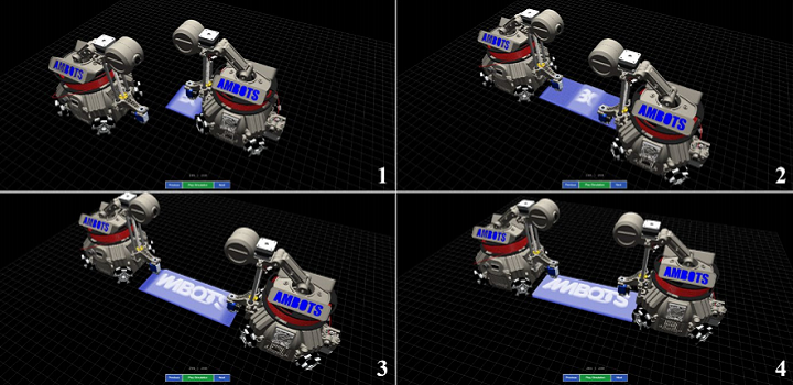
Cooperative 3D printing is made up of multiple independent, free-roaming robot 3D printers that receive instructions on how to print one part, or chunk, of a whole object. The mechanism makes it possible to autonomously complete large print jobs, with no interruptions, in a single piece, without human interaction. The parts are actually 3D printed on top of each other so they’re joined during the process and not after.

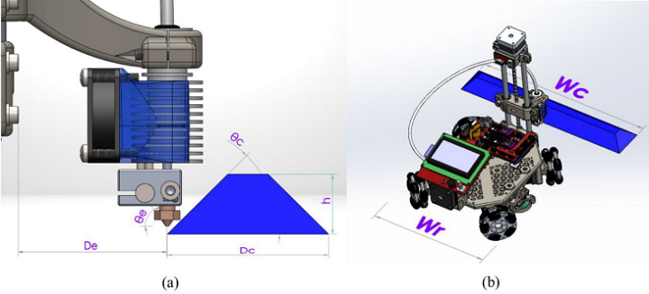
(a) Illustration of the chunk’s dimensions and printing limitations on the slope, and (b)a comparison of chunk width with robot width.
“Cooperative 3D printing solves physical scalability with the premise that multiple independent 3D printers can be used to produce a single object. These printers need to “cooperate” to produce objects that would normally exceed the size limitation of a traditional 3D printer. They must have the freedom to navigate a large area, such that their print range is limited only by the size of the print surface, as opposed to a fixed range imposed by the extrusion nozzle’s mechanism. To summarize, assuming the print surface is easy to scale, the potential print size will also be highly scalable,” McPherson wrote.
“This new mechanism also solves time scalability assuming new 3D printers that enter the fray can decrease the overall print time. Given that the number of printers is dynamic, we can quantify the time scalability as a function of the parallel efficiency from using any number of robots.”
The chunker design subdivides 3D models into chunks, which are then split up between the robots for 3D printing. The slicer converts these chunks into print commands for the robots, and the simulator creates a visual, using the slicer commands, that shows how real robots would complete their tasks. It’s important for the simulator to be properly designed, as it’s used to validate the chunker and slicer algorithms – if the simulator is not accurate, the rest of the process isn’t either.
In the rest of his thesis, McPherson describes how the slicer makes it possible to subdivide models so that chunks can be 3D printed in parallel, as well as demonstrating how to scale the slicer for more than two robots for additional degrees of spatial freedom.
“Results show that the developed slicer and simulator are working effectively,” McPherson wrote.
McPherson hopes that this project can help “lay the foundation for scalable Cooperative 3D printing,” which could open up a whole new direction of research for scaling 3D printing, and potentially even “revolutionize the way manufacturing processes are structured.”
“This thesis has presented, in detail, a feasible process for managing ?? 3D printing robots operating in parallel on a single print job, taking into account the geometric constraints, the communication requirements between robots, and the necessary pre-processing needed to properly subdivide a model for chunk-based printing,” McPherson concluded.
Discuss this research and other 3D printing topics at 3DPrintBoard.com or share your thoughts below.
The Chunker “chunk-based slicer” proposed for cobot 3D printing
In a paper recently published in Rapid Prototyping Journal, scientists detail a new slicing approach for multiple 3D printers working on the same object. In place of the typical layer-by-layer approach, this team proposes the “Chunker” that breaks CAD models down into chunks that are designated to different mobile additive manufacturing systems. According to the social […]
$500,000 3D printed construction project plans to use bacteria for building
In April 2018, assistant professor Michelle Bernhardt-Barry at the University of Arkansas was awarded a National Science Foundation research grant of $500,000 to support the development of 3D printed construction materials. Two months on, and further information about the 5 year project has been revealed, showing that it aims to use an usual method of binding natural […]