
A worldwide collective of researchers and scientists from universities, institutions, and hospitals have come together to produce a roadmap for 3D bioprinting. Published in Biofabrication, the paper details the current state of bioprinting, including recent advances of the technology in selected applications as well as the present developments and challenges. It also envisions how the […]
University of Pennsylvania: Controlling Defect Distribution for Programmed Failure
Chengyang Mo and Jordan R. Raney, of the Department of Mechanical Engineering and Applied Mechanics, University of Pennsylvania, explore the role of defects in mechanical properties in the recently published ‘Spatial programming of defect distributions to enhance material failure characteristics.’
In this study, the researchers are embracing and studying defects rather than avoiding them—as well as working to improve and control them. Defects in ‘classical metallurgy’ may ultimately result in ‘order of magnitude changes,’ for mechanical properties, while in metal 3D printing defects like grain boundaries may increase strength as the propagation of dislocation is stalled.
“However, the importance of defects is much more general in materials engineering,” state the researchers. “For example, defects are also vital in natural materials, where voids and imperfect interfaces are responsible for producing excellent combinations of mechanical properties such as stiffness, strength, and toughness in materials that are also lightweight.”
Nature often offers inspiration too, as in the example of nacre, a laminate structure found in marine shell animals—offering a combination of both hard and soft material with ‘imperfect interfaces.’ In 3D printing, the study of layers and the use of multiple materials has let to a wide range of studies focused on defects and how they are caused.
“With multimaterial 3D printing it is possible to enhance the toughness of material by arranging soft and stiff phases in architectures that mimic natural motifs, such as that of conch shell, nacre, and Stomatopod dactyl club,” explain the researchers. “Bioinspired composites such as glass fiber-reinforced polymers, alumina-reinforced polymers, and epoxy-carbon fiber have also been developed for direct write 3D printing processes.”
As failure occurs, defects may guide the process, altering one area while enhancing another. These occurrences cannot be ignored as they offer insight into ways to refine 3D printing and additive manufacturing processes.
“Since it is the defects rather than specific material pairings that produce the desired properties the findings of this work are relevant to a broad swathe of additive manufacturing processes (FDM, DIW, SLS, etc.) and materials (polymers, metals, ceramics, and composites),” explain the researchers.
The researchers 3D printed single-edge notched bend (SENB) samples, demonstrating the impacts of defects on failure properties. They focused on the use of PLA due to the ‘very high failure strain of the PDMS.’
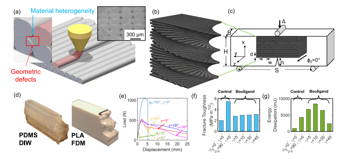
(a) Illustration of an extrusion-based additive manufacturing process with its characteristic systematic distribution of defects; inset is a microscope image showing the defect distribution between filaments within a plane perpendicular to the filaments; (b) Schematic of Bouligand structure; (c) Schematic of the single-edge notched bend (SENB) experimental tests, including the geometric parameters of the samples and the definitions of coordinates; (d) Photographs of samples after testing, showing similar fracture surfaces from two different materials (PLA and PDMS) printed with two different additive processes (FDM and DIW, respectively); (e) Load–displacement behavior of PLA samples as measured during SENB tests; (f) Fracture toughness of the PLA samples; (g) Energy dissipation of the PLA samples.
Multiple PLA samples were created using a Makergear M2 3D printer, and for this study, the researchers altered defects, changing their properties, thus varying normal failures. Printed samples each had two failure modes possible: fracture parallel with the filaments or fracture perpendicular to the filaments.
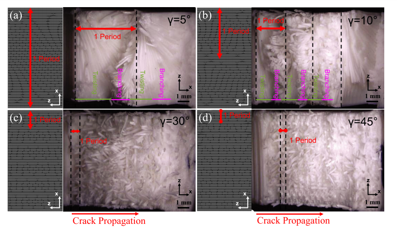
Schematic of filament orientations and optical images of the fracture surface for samples of all pitch angles: (a) 5◦, (b) 10◦, (c) 30◦, and (d) 45◦. The initial
crack front is located at the left of each image. Enlarged versions of these images are shown in Fig. S5 without annotations
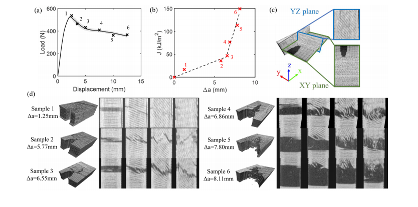
µCT data for six samples (with pitch angle γ = 10◦). (a) For each of the six samples the fracture testing was halted at one of the six indicated positions; (b) the energy release rate; (c) illustration of µCT result datum planes; (d) 3D reconstruction of the µCT data at the crack front region, and YZ slices ahead of the original crack front.
“By arranging these defects in a geometric motif inspired by natural materials, we achieved toughening mechanisms (intricate crack path and mixed loading at crack tips) comparable to those observed in natural materials and in bioinspired composites,” concluded the researchers.
“Moreover, by spatially varying the defect distribution (as observed in natural materials) one can in principle optimize for maximal combinations of strength and toughness. Unlike previous research, which focused on multimaterial 3D printing, which is highly materials specific (for example, the ratio of stiffness between the two materials, the interfacial adhesion, etc.), we have shown that the defect distribution alone can be controlled to enhance the failure characteristics even in single-material systems. These results are therefore relevant to a wide variety of materials systems and additive approaches.”
The study of mechanical properties in 3D printing is of massive interest to nearly anyone seriously interested in fabrication of prototypes and parts, prompting interest in studies such as how color has an effect, issues with porosity, improvements offered by finishing solutions, and much more. What do you think of this news? Let us know your thoughts! Join the discussion of this and other 3D printing topics at 3DPrintBoard.com.
[Source / Images: ‘Spatial programming of defect distributions to enhance material failure characteristics’]
The post University of Pennsylvania: Controlling Defect Distribution for Programmed Failure appeared first on 3DPrint.com | The Voice of 3D Printing / Additive Manufacturing.
Caterpillar Is a Powerful Rhino Grasshopper Plug-in for Greater Customization in 3D Printing
Bio-inspired 3D printings by (Zheng and Schleicher 2018)
Whether you are a serious 3D printing user or not, you have probably heard of Grasshopper, a popular add on of 3D modeling software Rhino. Grasshopper lets you use scripts and algorithms to create 3D models and generative designs. It is one of the quickest ways through which designers can get started with generative designs and lets you in a visual build things such as parametric designs or designs based on datasets. You may not yet be familiar with other features, however, recently outlined by University of Pennsylvania’s Hao Zheng in ‘Caterpillar – A GCode Translator in Grasshopper.’ Here, we learn more about a new plug-in Caterpillar and its ability to unleash full use of the three degrees of freedom of Computer Numerically Controlled (CNC) machines and non-traditional 3D printing. Caterpillar lets you generate Gcode from within Grasshopper. Your dataset or generative algorithm or existing model can now be quickly turned into Gcode that you can then optimize for 3D printing. This will enable people to quickly implement very creative and new 3D printing methods and techniques as well as enable the making of more non-traditional 3D printing processes.
Zheng points out what many of have noticed over time, as 3D printing users are simply not satisfied to stop and enjoy what has been supplied to them in terms of what is now traditional 3D printing in the layer-by-layer, bottom-to-top approach. For better control, Zheng postulates that users must be able to use ‘the three degrees of freedom’ – meaning X, Y, and Z and also go beyond them. More degrees of freedom and different ways of printing mean more applications are possible. The developers have added to conventional methods previously with accompaniments such as robotic arms, 3D printers that print on curved surfaces, as well as those that extrude alternative materials like wire.
For Caterpillar to do the necessary work, you must first give it the necessary data required. This means printers settings, to include many different parameters:
“Printer bed size (MM) contains three numbers (x, y, z), indicating the maximum printing size of the printer. Heated bed temperature (°C), extruder temperature (°C), and filament diameter (MM) are based on the printing material, which normally will not be changed once settled. Layer height (MM) and subdivision distance (MM) control the precision of the printing, while printing speed (%), moving speed (%), retraction speed (%), and retraction distance (MM) control how fast the printer will act when printing, moving without printing, and retracting materials. Extruder width (%) and extruder multiplier (%) together decide the width of the printed toolpaths.”
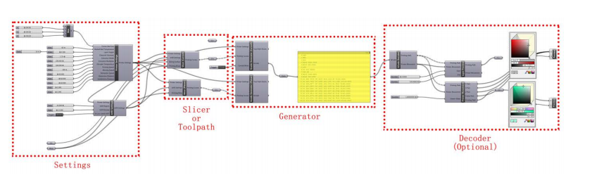
Work flow of Caterpillar in Grasshopper
Most users can just go with their default settings to be safe, but there may be some cases where you want to customize without default restriction. Infill settings must be considered too if you are slicing the model to provide infill.
For slicer and toolpath generation, there are numerous options:
- Planar slicer
- Curved slicer
- Curved toolpaths for special use
- User-defined toolpaths
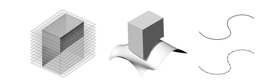
Planar Slicer (left), Curved Slicer (middle), User-defined Toolpath (right)
The workflow of the GCode generator then creates toolpaths based on points based on inputted curves, and optimization occurs:
“So before inputting the given curves to the dividing component, the program will detect and separate curved toolpaths and linear toolpaths, then divide the curved toolpaths as usual and extract the start and end points to represent the linear toolpaths.”
The GCode decoder then translates text files, assisting users in further design and control through keywords extraction and model rebuilding.
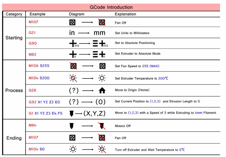
Commonly-Used Gcode.
“In the future, non-conventional customized 3D printing will be highly developed for both educational and industrial purposes,” concludes Zheng. “Low-cost 3-axis 3D printers with extra toolkits can handle a variety of tasks, providing an alternative for expensive robotic fabrication.”
In 3D printing, the central theme is customization. Users can create on an infinite scale, whenever they want, rapidly and affordability. Hardware choices continue to expand with the needs of 3D printing enthusiasts around the world, as do materials. Changes and evolution in software tend to be even more sweeping—and desired—as computer programs allow us to design objects and then control printing processes. While add-ons, plug-ins, and updates are continually available, software programs drive innovations—whether in allowing more advanced bioprinting and tissue engineering, scanning, or simulation of other processes. Caterpillar makes is much easier to implement, design and develop completely new 3D printing techniques and we can not wait to see the impact that this will have.
What do you think of this news? Let us know your thoughts! Join the discussion of this and other 3D printing topics at 3DPrintBoard.com.
Printing Simulation
[Source / Images: ‘Caterpillar – A GCode Translator in Grasshopper]
3D Printing News Sliced: AMUG, Desktop Metal, Stratasys, Royal DSM
This week Sliced, the 3D Printing Industry news digest, covers a variety of developments from the 2019 Additive Manufacturing Users Group (AMUG) conference as well as the Hannover Messe trade show. Elsewhere, we see novel applications in 3D printed electronics, artworks, watches, pattern-less investment casting and more. AMUG 2019 releases AMUG 2019 has now come to a close. […]
Penn State researchers integrate ‘Embodied Logic’ into 3D printed smart objects
Engineers from the University of Pennsylvania’s School of Engineering and Applied Science (SEAS) have created bioinspired 3D printed structures that move and react to its environment. Such objects do not require electronically-integrated systems, but, much like the venus fly trap, uses atmospheric stimuli to operate; the Penn State team have dubbed this as “embodied logic”. The […]
UPenn Researchers Using Jammed Microgels as 3D Bioprinting Inks
Diversity in microgel compositions for ink fabrication.
A trio of researchers from the University of Pennsylvania have published a paper, titled “Jammed Microgel Inks for 3D Printing Applications,” on their use of jammed microgels as inks for bioprinting, in order to address the various limitations of 3D bioprinting with hydrogels. Researchers and scientists use 3D bioprinting to organize materials and cells into 3D structures, and while it can do amazing things, the technology still has a lot of challenges, like materials restrictions and achieving the correct resolution and stability for printed constructs. While soft hydrogel materials are often used in tissue engineering, thanks to tunable biochemical and biophysical properties, it’s hard to print them without using some sort of additive or modification.
The abstract reads, “3D printing involves the development of inks that exhibit the requisite properties for both printing and the intended application. In bioprinting, these inks are often hydrogels with controlled rheological properties that can be stabilized after deposition. Here, an alternate approach is developed where the ink is composed exclusively of jammed microgels, which are designed to incorporate a range of properties through microgel design (e.g., composition, size) and through the mixing of microgels. The jammed microgel inks are shear‐thinning to permit flow and rapidly recover upon deposition, including on surfaces or when deposited in 3D within hydrogel supports, and can be further stabilized with secondary cross‐linking. This platform allows the use of microgels engineered from various materials (e.g., thiol‐ene cross‐linked hyaluronic acid (HA), photo‐cross‐linked poly(ethylene glycol), thermo‐sensitive agarose) and that incorporate cells, where the jamming process and printing do not decrease cell viability. The versatility of this particle‐based approach opens up numerous potential biomedical applications through the printing of a more diverse set of inks.”

Jammed microgel ink fabrication, rheological properties, and extrusion.
The microparticles found in jammed systems are packed pretty densely, and physical interactions with surrounding particles immobilize them. This results in macroscopic materials that behave as solids, until movement is induced by applied force.
“In the case of highly dense microgel formulations such as those used here, the microgel volume may deform elastically below the yield stress, but there is no movement of individual microgels. However, an application of sufficient stress to a volume of microgels results in movement of the microgels relative to one another as stress overcomes the packing forces that resist motion,” the researchers explained. “Further, upon reducing an applied stress below the yield stress, the system recovers. This flow and recovery of the jammed system in response to stress meets the design demands on inks for 3D printing, without the need for changes or rearrangements in the molecular structures of the materials for printing. Additionally, the jamming of microgels should be independent of microgel composition, potentially allowing the printing of any hydrogel material that can be processed into microgels.”
Jammed microgels work as bioinks because they allow cross‐linked hydrogel particles to be formed as an aggregate bulk, which can then be extruded as a stable filament without using any other material or having to engineer any interparticle interactions. The researchers formed microgel inks through the use of microfluidic devices.
The researchers said, “There is much versatility to this approach, allowing the fabrication of microgels from numerous materials, across a wide range of sizes, and incorporating biological components (e.g., cells, therapeutics).”
Jammed microgel ink printing on surfaces or within hydrogels.
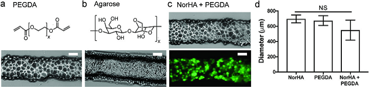
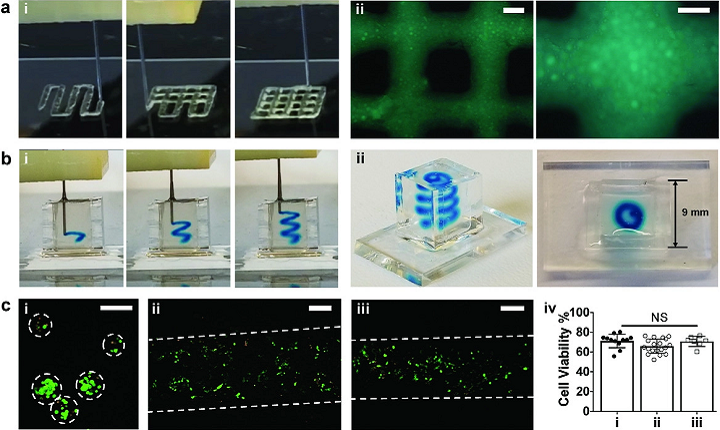
The team used norbornene‐modified hyaluronic acid (NorHA), poly(ethylene glycol) diacrylate (PEGDA), and agarose to make their microgels, which definitely displayed the kinds of rheological properties important for 3D printing, such as shear-thinning behavior, elastic response at low strains, and the ability to flow during extrusion and stabilize quickly after deposition. A modified Revolution XL 3D printer was used to fabricate the microgels into a four-layer lattice.
Mechanical forces disrupted the 3D printed structures as expected, so the team used post‐cross‐linking to chemically link the particles together.
“As an example, during the jamming process, additional cross‐linker (dithiothreitol) and photoinitiator (Irgacure 2959) were included, and ultraviolet (UV) light led to interparticle cross‐linking due to the presence of remaining unreacted norbornene groups. Printed and post‐cross‐linked lattice structures could subsequently be handled with forceps with no apparent loss in structural integrity,” the researchers said.
Additionally, when the printed and post‐cross‐linked cuboid structures were placed in cell culture medium, they held their dimensions and structure for a whole week, and the “compressive moduli of printed constructs” was increased by introducing interparticle bonds to post‐cross‐linking. This happened at a lower value than hydrogels that are made of the same formulation used to make microgels; when combined, these results that it’s possible to 3D print microgel inks, “as the jammed ink properties support printing and short‐term stability.”
“We believe the printing of jammed microgel inks opens up the possibility for the printing of a range of diverse materials and structures. To illustrate this, we utilized the gel‐in‐gel printing method of microgel inks into support hydrogels to print heterogeneous structures,” the researchers said.
“Further, microgel inks were used for the fabrication of microchannels within support hydrogels. To accomplish this, i) agarose‐based microgel inks were extruded into a support hydrogel, ii) the support hydrogel was stabilized by covalent cross‐linking, and iii) the agarose microgels were removed through dissolution with an increase in temperature to 37 °C and in the presence of agarase, leaving behind a perfusable channel within the stabilized support material.”
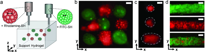
Printing of jammed NorHA microgel inks in diverse patterns within shear‐thinning support hydrogels.
The research shows that microgel inks can definitely be used to 3D print heterogeneous structures without damaging any cells.
“The microgel approach permits control over cellular microenvironments through microgel design without the need for additives that may disrupt cell behavior,” the researchers concluded. “These unique materials offer exciting possibilities for new approaches to biofabrication and expand on the availability of inks for printing.”
Co-authors of the paper are Christopher B. Highley, Kwang Hoon Song, Andrew C. Daly, and Jason A. Burdick.
Discuss this research and other 3D printing topics at 3DPrintBoard.com or share your thoughts below.