Researchers Run Simulation Tests on Their 3D Printed CubeSat Before LEO Mission

A pair of researchers from Shantou University in China explored designing and manufacturing a CubeSat with 3D printing, which we have seen in the past. CubeSats, which are basically miniaturized satellites, offer plenty of advantages in space exploration, such as low cost, a short research cycle, and more lightweight construction, but conventional methods of manufacturing often negate these. Using 3D printing to make CubeSats can help achieve accurate details as well.
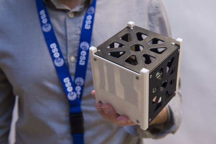
[Image: ESA]

The researchers, Zhiyong Chen and Nickolay Zosimovych, recently published a paper on their work titled “Mission Capability Assessment of 3D Printing Cubesats.”

“With the successful development of integrated technologies, many spacecraft subsystems have been continuously miniaturized, and CubeSats have gradually become the main executors of space science exploration missions,” they wrote.

The main task driving research paper is an LEO, or Low Earth Orbit, CubeSat mission, which would need to accelerate to a maximum of 5 g during launch.

“…the internal operating temperature range of the CubeSat is from 0 to 40 °C, external temperature from -80 to 100 °C,” the researchers explained.

During the design process, the duo took into account environmental factors, the received impact load during the launch process, and the surrounding environment once the CubeSat reached orbit. Once they determined the specific design parameters, ANSYS software was used to simulate, analyze, and verify the design’s feasibility.

PLA was used to make the mini satellite, which is obviously shaped like a cube. Each cube cell, called a unit, weighs approximately 1 kg, and has sides measuring 10 cm in length.

“The framework structure for a single CubeSat provides enough internal workspace for the hardware required to run the CubeSat. Although there are various CubeSat structure designs, several consistent design guidelines can be found by comparing these CubeSats,” the researchers wrote about the structure of their CubeSat.

These guidelines include:

  • a cube with a side length of 100 mm
  • 8.5 x 113.5 mm square columns placed at four parallel corners
  • usually made of aluminum for low cost, lightweight, easy machining

The CubeSat needs to be big enough to contain its power subsystem (secondary batteries and solar panels), in addition to the vitally important thermal subsystem, communication system for providing signal connections to ground stations back on Earth, ADCS, and CDH subsystems. It also consists of onboard antennae, radios, data circuit boards, a three-axis stability system, and autonomous navigation software.

“The adoption of this technology changes the concept of primary and secondary structure in the traditional design process, because the whole structure can be produced at the same time, which not only reduces the number of parts, reduces the need for screws and adhesion, but also improves the stability of the overall structure,” the pair wrote about using 3D printing to construct their CubeSat.

The mission overview for this 3D printed CubeSat explains that the device needs to complete performance tests on its camera payload for reliability evaluation, and test the effectiveness of any structures 3D printed “in an orbital environment.”

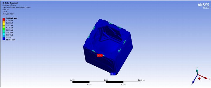
The Von mises stress diagram of the CubeSat structure.

In order to ensure that it’s ready to operate in LEO, the CubeSat’s structures was analyzed using ANSYS’ finite element analysis (FEA) software, and the researchers also performed a random vibration analysis, so that they can be certain it will hold up under the launch’s impact load.

“The CubeSat structure is validated by the numerical experiment. During launch process, CubeSat will be fixed inside the P-Pod, and the corresponding structural constraints should be added to the numerical model. In addition, the maximum acceleration impact during the launch process should also be considered. Static Structural module of ANSYS is used for calculation and analysis, the results show that the maximum stress of CubeSat Structure is 8.06 MPa, lower than the PLA yield strength of 40 Mpa,” the researchers explained.

Running in LEO, the 3D printed CubeSat will go through a 100°C temperature change, and the structure needs to be able to resist this, so the researchers also conducted a thermal shock test, which showed an acceptable thermal strain.

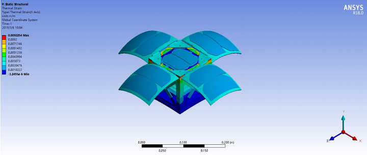
The thermal strain diagram of the CubeSat structure.

The team also conducted random vibration simulation experiments, so they could conform the structure of the 3D printed CubeSat to emission conditions. They simulated typical launch vibration characteristics, using NASA GEV qualification and acceptance as reference.

“The specific contents of the experiment include “Harmonic Response” and “Random Vibration”. Two identical harmonic response were performed before and after the random vibration test to assess the degree of structural degradation that may result from the launch load,” the researchers explained.

“This experiment helps us to evaluate the natural frequency of the structure, and the peak value indicates that the tested point (bottom panel) has reached the resonant frequency.”

Pre/Post Random Vibration test comparison between the curves of Harmonic Response.

As seen in the above figure, both the trend and peak points of the two curves are close to each other, which shows that there was no structural degradation after the vibration test, and that the structure itself conforms to launch stiffness specifications.

“As the primary performer of today’s space exploration missions, the CubeSat design considers orbit, payload, thermal balance, subsystem layout, and mission requirements. In this research, a CubeSat design for performing LEO tasks was proposed, including power budget, mass distribution, and ground testing, and the CubeSat structure for manufacturing was combined with 3D printing technology,” the researchers concluded.

“The results show that the CubeSat can withstand the launch loads without structural damage and can meet the launch stiffness specification.”

Discuss this and other 3D printing topics at 3DPrintBoard.com or share your thoughts below. 

The post Researchers Run Simulation Tests on Their 3D Printed CubeSat Before LEO Mission appeared first on 3DPrint.com | The Voice of 3D Printing / Additive Manufacturing.

Purdue Researchers Form Startup for the 3D Printing of Energetic Materials

Allison Murray and Jeffrey Rhoads in 2017

Energetic materials are a class of material that contains high amounts of stored chemical energy that can be released, and they are used in everything from airbags to explosives. Last year, a team of researchers from Purdue University used 3D printed energetic materials to create a mini shock wave, and have since continued their work with these unique materials.

The researchers can safely 3D print energetic materials, featuring fine geometric features, for less money, at greater speeds. Now, Jeffrey Rhoads, a professor in the university’s School of Mechanical Engineering, has teamed up with several other colleagues, including former Purdue research assistant professor Emre Gunduz, to start a faculty-owned startup focused on making the energetic materials, like propellants, solid rocket fuels, and pyrotechnics, along with the 3D printers that can produce them.

Jeffrey Rhoads

Rhoads is now the COO of Next Offset Solutions, with Gunduz, now a professor at the Naval Postgraduate School in Monterey, California, as its CTO. The startup makes its energetic materials with a process – patented with help from the Purdue Office of Technology Commercialization – that allows the 3D printer to produce viscous materials, which have a clay-like consistency and can be difficult to extrude. The method makes it possible for the team to precisely, and safely, deposit the energetic materials.

Rhoads said, “It’s like the Play-Doh press of the 21st century.

“We have shown that we can print these energetic materials without voids, which is key. Voids are bad in energetic materials because they typically lead to inconsistent, sometimes catastrophic, burns.”

According to Rhoads, the startup’s 3D printer doesn’t use any solvents to lower the viscosity, which makes the process faster, more environmentally friendly, and less expensive. Additionally, the 3D printer is also much safer due to a remote control feature.

“You don’t have to have a person there interfacing with the system,” Rhoads explained. “That’s a big advantage from the safety standpoint.”

Monique McClain, a doctoral candidate in Purdue’s School of Aeronautics and Astronautics, demonstrates how it’s possible to 3D print extremely viscous materials.

The 3D printer functions a lot like more conventional 3D printers, with the exception of how it extrudes the highly viscous materials. High-amplitude ultrasonic vibrations are applied to the 3D printer’s nozzle, which lowers the friction on the nozzle walls and allows for more precise flow control of the material.

While Next Offset Solutions is mainly focused on producing energetic materials, it’s not adverse to further applications, other Purdue researchers have already used the startup’s novel method to 3D print things like personalized drugs and biomedical implants. For instance, because its 3D printing material has already been qualified by the departments of Defense and Energy, the startup hopes to provide its technology and products to the departments and their contractors.

The startup is also focusing on additional advanced evaluation, research, development, and testing in the 3D printing and energetic materials space. But its original research definitely aligns with the university’s Giant Leaps celebration as part of its 150th anniversary, which celebrates Purdue’s “global advancements in health.”

Purdue researchers have published several papers focusing on 3D printing energetic and viscous materials in the Additive Manufacturing journal, including:

Take a look at the video below to see the viscous material 3D printing process for yourself:

What do you think? Discuss this work and other 3D printing topics at 3DPrintBoard.com or share your thoughts in the Facebook comments below. 

[Source/Images: Purdue University]

Acoustic Nozzles Improve the Performance of 3D Printed Parts

Usually when we’re talking about 3D printing in terms of acoustics, it has to do with making a good set of speakers. But, recent research has determined that acoustic signal processing could be used to monitor the build quality of a 3D printed part while in progress. There are 3D printable sound-shaping super-materials, and 3D printed objects have even been implanted with sound data for tagging purposes. New research out of Nanyang Technological University (NTU) in Singapore looks at using acoustics to manipulate microparticles inside the actual 3D printing ink itself to improve the final object’s performance and functionality.

Properly orienting and aligning the fibers in a polymer matrix could help transfer loads from critical areas for better performance, and creating 3D scaffolds with a controlled hierarchical structure at the nano- and micro-scale levels could increase their mechanical strength, which is good for cell and tissue regeneration and load-bearing bone defect repair. In addition, using surface acoustic waves to focus microparticles inside the microchannel could delay accumulation on the wall, which can improve extrusion-based 3D printing.

Schematic diagram of experimental setup.

Researchers from NTU recently published a paper on their 3D printing work with acoustics, titled “Cells alignment and accumulation using acoustic nozzle for 3D printing.”

The abstract reads, “Arrangement or patterning of microparticles/cells would enhance the efficiency, performance, and function of the printed construct. This could be utilized in various applications such as fibers reinforced polymer matrix, hydrogel scaffold, and 3D printed biological samples. Magnetic manipulation and dielectrophoresis have some drawbacks, such as time-consuming and only valid for samples with specific physical properties. Here, acoustic manipulation of microparticles in the cylindrical glass nozzle is proposed to produce a structural vibration at the specific resonant frequency. With the acoustic excitation, microparticles were accumulated at the center of the nozzle and consequently printed construct at the fundamental frequency of 871 kHz. The distribution of microparticles fits well with a Gaussian distribution. In addition, C2C12 cells were also patterned by the acoustic waves inside the cylindrical glass tube and in the printed hydrogel construct. Overall, the proposed acoustic approach is able to accumulate the microparticles and biological cells in the printed construct at a low cost, easy configuration, low power, and high biocompatibility.”

Morphology and distribution of the cells in 5% GelMA without the acoustic excitation on (a) day 1, (b) day 4, (c) day 7, and with the acoustic excitation on (d) day 1,(e) day 4, (f) day 7.

The team numerically and experimentally studied the structural vibration of a cylindrical tube, as well as the patterning of the microparticles and cells inside of it.

“Firstly, the resonant frequency was numerically predicted and validated with experiment,” the researchers wrote. “Subsequently, the distribution of microparticles and biological cells inside the cylindrical tube and printed construct was investigated. Lastly, the growth of biological cells undergone the acoustic excitation was monitored for up to 7 days.”

During an acoustic excitation, a mixture of C2C12 cells embedded in 2 ml of 5% GelMA was printed on a 4″ petri dish, with the nozzle perpendicular to the print bed. The researchers discovered that during the excitation, most of the microparticles that were initially suspended in fluid ended up accumulating at the center of the glass tube. There seemed to be a good overall agreement between the experimental results and numerical simulation of the excitation frequency, along with the location of pressure nodes in the glass tube.

The researchers further evaluated their acoustic nozzle’s performance using C2C12 muscle cells, and determined that without the excitation during printing, the distribution of the cells in the tube was very random.

Microparticle distribution in the cylindrical tube (a) without and (b) with the acoustic excitation at 877 kHz.

“Results of simulation and experiment are agreeable with a slight difference in the resonant frequency (< 2%). In the experiment, microparticles were accumulated at the center of the nozzle and consequently printed construct. The distribution of microparticles fits well in a Gaussian curve with a standard deviation of (V = 0.16 mm). Furthermore, the acoustic excitation could also be used for patterning biological cells in the 3D printed construct of GelMA,” the researchers concluded. “Subsequently, the distribution of cells was quite dense at the center of the printed structure, and accumulated C2C12 cells had greater growth and differentiation in comparison to the suspended ones in the control group.”

Co-authors of the paper are Yannapol Sriphutkiat, Surasak Kasetsirikul, Dettachai Ketpun, and Yufeng Zhou.

Discuss this research and other 3D printing topics at 3DPrintBoard.com or share your thoughts below. 

Researchers from S2A Lab Experimenting with Remote 3D Printing Control

Late last year, we learned that researchers with the Smart and Sustainable Automation Research Lab (S2A Lab) at the University of Michigan College of Engineering had been working to develop an algorithm that would double the speed of desktop 3D printers. It works by using Filtered B-Spline (FBS) algorithms to adjust 3D printer control and mitigate unwanted vibrations while the print speed goes up. Earlier this week, we received an update on the team’s vibration compensation algorithm from Chinedum Okwudire, PhD, an associate professor of mechanical engineering at the university and the director of S2A Lab.

“Over the past year we have been working to integrate our vibration compensation algorithm into Marlin and release it open-source to the 3D printng community. But we have not succeeded because of the low computational power and memory on the ATMega2560 microcontroller which cannot support our algorithm,” Professor Okwudire told 3DPrint.com. “We are now looking into releasing it open-source on firmware that run on more powerful microcontrollers. More updates on this to follow as we make more progress.”

CAD model of XYZ Calibration Cube commonly used for determining acceptable acceleration and jerk speed limits of desktop 3D printers.

But the innovative vibration compensation algorithm isn’t the only thing the researchers in the S2A Lab have been working on lately.

“In the meantime, we have been experimenting with a new way of controlling 3D printers, where stepper motor commands (and other low-level control commands) are generated in the Cloud, rather than on a microcontroller,” Professor Okwudire explained to us. “The idea is not too different from how video streaming works, and is a refined version of how OctoPrint, Astroprint and 3DPrinterOS work. It gives Wi-Fi enabled 3D printers access to advanced algorithms like ours, running on the Cloud, without need for very powerful microcontrollers. Our initial results have been very encouraging. We were able to compensate the vibration of a Lulzbot Taz 6 3D printer situated in Michigan from cloud-based controllers in South Carolina and in Australia without much problems, hence slashing printing time by up 54% compared to using Marlin. Details of this work are published in the special issue on Innovations in 3D Printing of the open-access journal Inventions.”

The team published the details of their work in a paper, titled “Low-Level Control of 3D Printers from the Cloud: A Step toward 3D Printer Control as a Service,” in a special issue of open access journal Inventions all about 3D printing innovations; co-authors include Professor Okwudire, Sharankumar Huggi, Sagar Supe, Chengyang Huang, and Bowen Zeng.

Overview of setup for experiments.

The abstract reads, “Control as a Service (CaaS) is an emerging paradigm where low-level control of a device is moved from a local controller to the Cloud, and provided to the device as an on-demand service. Among its many benefits, CaaS gives the device access to advanced control algorithms which may not be executable on a local controller due to computational limitations. As a step toward 3D printer CaaS, this paper demonstrates the control of a 3D printer by streaming low-level stepper motor commands (as opposed to high-level G-codes) directly from the Cloud to the printer. The printer is located at the University of Michigan, Ann Arbor, while its stepper motor commands are calculated using an advanced motion control algorithm running on Google Cloud computers in South Carolina and Australia. The stepper motor commands are sent over the internet using the user datagram protocol (UDP) and buffered to mitigate transmission delays; checks are included to ensure accuracy and completeness of the transmitted data. All but one part printed using the cloud-based controller in both locations were hitch free (i.e., no pauses due to excessive transmission delays). Moreover, using the cloud-based controller, the parts printed up to 54% faster than using a standard local controller, without loss of accuracy.”

Control as a Service (CaaS) is just one of several examples, such as cloud robotics and cloud manufacturing, of paradigms inspired by, and built on the shoulders of, cloud computing and other service-oriented architectures (SOA). It works like this: a device’s low-level control functionalities are moved out of a local controller to the Cloud, where they can then be accessed on-demand remotely. Multiple 3D printing services rely on SOAs and cloud computing, and the trend of controlling 3D printers remotely through a web-based wireless host platform, such as OctoPrint, 3DPrinterOS, and Astroprint, continues to grow.

But, these types of platforms send G-codes, or the equivalent, from the Cloud to the 3D printer while at the same time assigning lower level computations to a microcontroller. So these don’t offer the same kind of CaaS that the S2A Lab is working to develop.

“3D printers are an excellent case study for advancing CaaS, especially since many of them (particularly those of the desktop kind) have very limited computational resources on their local controllers,” the researchers wrote. “The control performance of desktop 3D printers could be significantly improved at low cost via cloud-based control algorithms provisioned through CaaS.”

The researchers used a Lulzbot Taz 6 3D printer with dual extruders for their experiments, though mentioned in the paper that industrial 3D printers could also stand to benefit from this kind of advanced control algorithm.

“Therefore, this paper presents preliminary work on low-level motion control of a desktop 3D printer from the Cloud, as a first step towards in-depth research into 3D printer CaaS (3DPCaaS). It not only shows that low-level control of 3D printers from the Cloud is feasible, but also demonstrates huge improvements in 3D printing speed and accuracy that can be achieved using an advanced cloud-based motion controller over a standard local controller,” the researchers wrote.

Prints of Medieval Castle using: (a) local controller (Marlin); (b) cloud-based controller in South Carolina; and (c) cloud-based controller in Australia. The portions of the prints highlighted in dashed rectangles failed (broke off) during printing due to delicate support structures.

The S2A Lab set up a website as a gathering place for people who want to continue researching the idea, and testing 3DPCaaS on their own 3D printers.

“This work is still very experimental but it has shown great promise,” Professor Okwudire told 3DPrint.com. “It may just be the next big thing in 3D printer control, where printers can gain on-demand access to powerful algorithms that boost their performance without need to upgrade to very powerful microcontrollers. What we picture is an OctoPrint-like platform where people can upload G-Codes and remote control their printers with the help of advanced algorithms like ours running from the Cloud.”

Discuss this and other 3D printing topics at 3DPrintBoard.com or share your thoughts below.

Fabrisonic’s Whitepaper on Metal 3D Printed Heat Exchangers for NASA JPL

Founded in 2011, Ohio-based Fabrisonic uses its hybrid metal 3D printing process, called Ultrasonic Additive Manufacturing (UAM), to merge layers of metal foil together in a solid-state thanks to high frequency ultrasonic vibrations. Fabrisonic mounts its patented hybrid 3D printing process on traditional CNC equipment – first, an object is built up with 3D printing, and then smoothed down with CNC machining by milling to the required size and surface. No melting is required, as Fabrisonic’s 6′ x 6′ x 3′ UAM 3D printer can “scrub” metal foil and build it up into the final net shape, and then machines down whatever else is needed at the end of the process.

Last year, Fabrisonic’s president and CEO Mark Norfolk told 3DPrint.com at RAPID 2017 that about 30% of the company’s business was in heat exchangers, as the manufacturing process is a lot smoother thanks to its low-temperature metal 3D printing technology – no higher than 250°F. UAM makes it possible to join metal alloys that are notoriously difficult to weld, such as 1000, 2000, 6000, and 7000 series copper, aluminum, stainless steel, and exotic refractory metals…all of which are used in the heat management systems at NASA’s Jet Propulsion Laboratory (JPL).

[Image: Sarah Saunders]

Justin Wenning, a production engineer at Fabrisonic I spoke with at RAPID 2018 this spring, recently published a whitepaper, titled “Space-grade 3D Metal Printed Heat Exchangers,” that takes a deep dive into the work he’s been doing with Fabrisonic’s 3D printed metal heat exchangers for aerospace applications. The company participated in a two-year program at JPL, and 3D printed a new class of metal heat exchanger that passed JPL’s intense testing.

“For every interplanetary mission that JPL oversees, numerous critical heat exchanger devices are required to regulate the sensitive, on-board electronic systems from temperature extremes experienced in space. These devices can be small (3 in. x 3 in.) or large (3 ft. x 3 ft.),” Wenning wrote in his whitepaper.

For many years, NASA glued bent metal tubes along, and fastened them to, the exterior of a space vehicle’s structure, which weigh a lot and do not perform well thermally. These devices were also assembled and quality-checked by hand, so production could take up to nine months. At the end of its partnership with NASA JPL, Fabrisonic showed that 3D printing can be used to improve upon all of these issues.

Evolution of UAM 3D printed heat exchanger with NASA JPL. Samples began small to
evaluate benchmark burst and helium leak performance in 2014. The team then began focusing on technology scale-up and system integration. The culmination is a full-size, functioning heat exchanger.

The UAM system does not use any controlled atmospheres, so the part size and design range greatly. NASA JPL first started working with Fabrisonic in 2014, thanks to a JPL Spontaneous R&TD grant, to look into small, simple UAM heat exchangers, before moving up to larger structures in 2015 through NASA’s SBIR/STTR program. The result was a full-size, functioning heat exchanger prototype for the Mars 2020 rover mission that was fabricated in far less time, with a 30% lighter mass.

The 3D printed heat exchangers that Fabrisonic creates involve building pumped-fluid loop tubing right into the structure for additional efficiency and robustness, as the company’s UAM process can also be used to mix and match materials, like copper and aluminum.

UAM starts with a metal substrate, and material is then added to and removed from the structure to make the device’s internal passageways. To help with material deposition, a proprietary water-soluble support structure is added, before adding strength and features, respectively, with optional heat-treating and final CNC machining. Fabrisonic then added SS tubing, which helps with fitting attachments, to the aluminum structure with friction welding for NASA JPL’s development parts.

NASA JPL also needed to raise its technology readiness level (TRL) from 3 to near 6. During the program, Fabrisonic and its EWI affiliate 3D printed and tested dozens of different heat exchangers, in order to develop a final prototype for ground-based qualification standards based off of NASA JPL’s existing heat exchangers.

UAM process steps for fabricating NASA JPL heat exchangers.

The NASA JPL TRL 6 qualification included several tests, including proof pressure testing to 330 PSI, two-day controlled thermal cycling from -184°F to 248°F in an environmental chamber, and vibration testing on an electrodynamic shaker, which simulated a common day rocket launch (1-10 G) in all orientations while attached to a dummy mass at the same time for imitating a normal hosted electronics package. Other tests included:

  • Burst testing greater that 2500 PSI with a 0.030-in. wall thickness
  • Helium leak testing to less than 1×10⁻⁸ cc/s GHe between thermal and vibration testing
  • Full 3D CT scans of each specimen before and after mechanical testing, in order to evaluate void density and any accumulated testing damage

JPL project with copper embedded. [Image: Sarah Saunders]

Each of the three UAM 3D printed heat exchanger components passed the qualifications, which raised the technology to its goal of near TRL 6. To corroborate the results, NASA JPL scientists completed more helium leak and burst testing, along with thermal shock testing on certain devices; this involved submerging certain heat exchangers in liquid nitrogen (-320°F) to test their bi-metallic friction welded stainless steel aluminum joints. According to the whitepaper, the joints were “robust and helium leak tight” post-submersion.

Fabrisonic’s new class of 3D printed metal heat exchanger, developed under NASA JPL, has uses in other commercial production applications, which the company is currently exploring.

“For instance, the lack of melting in UAM enables the integration of multiple metals into one build since high temperature chemistry is avoided,” Wenning wrote. “Thus, copper may be integrated as a heat spreader in critical locations improving thermal performance with a small weight penalty.”

Because of its low temperatures, UAM can also be used to embed sensors into solid metal. In 3D printed heat exchangers, sensors could help monitor system health and improve control by being integrated in important locations.

Discuss this story and other 3D printing topics at 3DPrintBoard.com or share your thoughts below.

[Images: Fabrisonic unless otherwise noted]