University of Cape Town: Feasibility in Design for Affordable 3D Printed Horn Antennas

Ming Gao has prepared a thesis, ‘Design and feasibility evaluation of low-cost 3D printing of Horn Antennas’, for the Department of Electrical Engineering at the University of Cape Town. Focusing on more affordable microwave and RF devices, Gao explores the realities of using additive manufacturing and metallization techniques, including 3D printing and testing a sample antenna.

Field regions of an antenna [3].

The business of creating lightweight antennas continues to grow globally, and especially as the demand for technology like drones grows. In the case of a drone, a typical metallic antenna would weigh too much, especially in applications where the device was responsible for carrying items.

Conventional techniques today involve casting and milling, but they stand in stark contrast to the benefits of 3D printing as they are time-consuming and expensive due to the more materials and amount of precision required. Waveguide dimensions must be exact as antennas are expected to live up to ‘stringent requirements,’ and can also be difficult to make.

Wave guides deliver electromagnetic waves in a variety of formats:

  • TEmn mode
  • TMmn mode
  • TEM mode

Efficiency for an antenna is measured by the amount of power delivered to the antenna itself, relative to the power radiating out, with users showing success in using FDM 3D printing for production of necessary components.

Radiation beamwidths and lobes of an antenna pattern [3].

“Beam widths and sidelobe levels are characterizations of the antenna radiation pattern. The beam width is a measure of the main beam at half power, or −3 dB from the peak power, also known as the half-power beam width (HPBW),” said Gao. “Sidelobes represent radiation that is not in the direction of the main beam. The sidelobe level (SLL) of a pattern is measured as the difference between the peak of the main beam and the peak of the first sidelobe to either side of the main beam.”

Fundamental modes for the rectangular (left) and circular (right) waveguides [9].

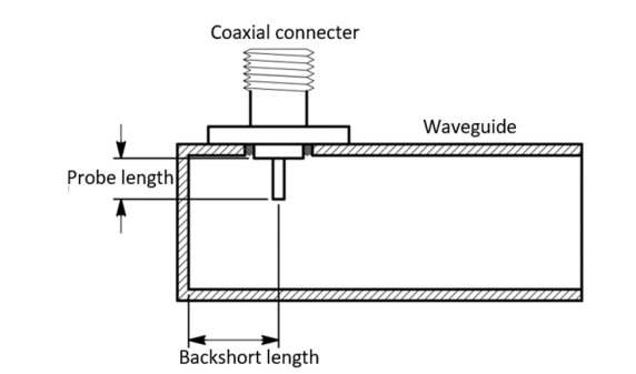
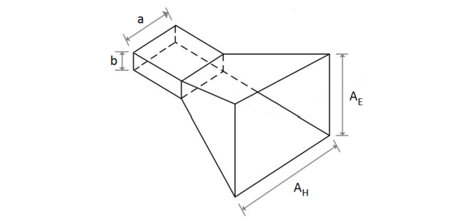
Typical waveguide structure and parameters [16].

Using an Ultimaker 2+ FDM-based 3D printer with ABS as the chosen material, the following samples were fabricated:

  • X-Band pyramidal horn – this sample was an easy design as Gao had access to a good model for replication within the University’s department. Dimensions were carefully measured for the FEKO simulation, and the antenna was coated with NSCP, a nickel-based conductive spray paint. Measured antenna properties were found to be very similar to the commercially produced horn.
  • Ku-Band pyramidal and conical horns – these horns were both metallicized using copper-plating performed by TraX Interconnect, and coating with NSCP. Comparisons showed that the horns did ‘achieve a higher reflection coefficient than simulation,’ but unfortunately, only 3.16 of the power was reflected through the antenna.

Structure of a pyramidal horn [12].

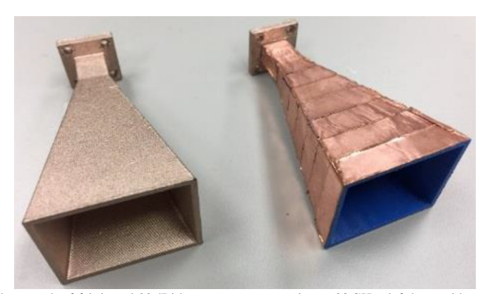
Photograph of commercial X-band pyramidal horn.

Photograph of fabricated X-band pyramidal horn.

“Both horn antennas provide very directional beams and high gain. The benefit of the pyramidal horn is that it is more suitable if low x-pol is needed, but it is also more difficult to metallize due to sharp edges. The conical horn has a symmetrical plane which is suited for dual-polarization and circular polarization, and easier to metallize. However, in contrast to the pyramidal horn, it has a higher x-pol leakage,” concluded the researchers.

“With the limitation of available resources, the overall experiments and measurements showed very promising results, and the 3D printing and conductive coatings have been considered successful. Additionally, the entire fabrication process is very low-cost in comparison to the costs of traditional manufacturing.”

Photograph of fabricated 20 dBi horn antennas operating at 28 GHz: left horn with copper conductive paint and right horn with copper tape on the surface [31].

3D printing has accompanied the design and fabrication of numerous antennas, with new projects resulting in 3D printed antennas for improving multi-beam applications, liquid metal antennas, nanoantenna arrays, and more. What do you think of this news? Let us know your thoughts! Join the discussion of this and other 3D printing topics at 3DPrintBoard.com.
[Source / Images: ‘Design and feasibility evaluation of low-cost 3D printing of Horn Antennas’]

The post University of Cape Town: Feasibility in Design for Affordable 3D Printed Horn Antennas appeared first on 3DPrint.com | The Voice of 3D Printing / Additive Manufacturing.

Now You Can Download and 3D Print NASA’s Multi-Tool, and Other Space-Related Stuff, for Free

1013385 81 95807 QpEKtPdtS

Via Core77

The NASA 3D Resources website has posted hundreds of 3D models, images, textures and visualizations that you can download for free. As far as models, they’ve got everything from astronaut gloves and spacesuits to satellites and spacecraft:

Read more and check out all the 3D offerings from NASA

NASA says

Our team’s goal is to provide a one-stop shop for 3D models, images, textures, and visualizations. We offer these assets for your use, free and without copyright. We recognize that the site is only as good as its contributors and thank them kindly.

We welcome feedback and comments. Tell us how you’re using our models, and let us know what you think: arc-special-proj@lists.nasa.gov

3D Printed Surfboard: Researchers Test Different Bio-Inspired Core Structures

Just as a New Zealand-based surfer was inspired by the humpback whale and the microgrooves of shark skin when creating his surfboard fins, so too was a team of international researchers inspired by the natural world in their structure study of an on-water sports board. In their recently published paper, “3D Printing On-Water Sports Boards with Bio-Inspired Core Designs,” they explain their work advancing the board by using 3D printing and different bio-inspired core structures, such as the honeycomb.

“Modeling and analyzing the sports equipment for injury prevention, reduction in cost, and performance enhancement have gained considerable attention in the sports engineering community. In this regard, the structure study of on-water sports board (surfboard, kiteboard, and skimboard) is vital due to its close relation with environmental and human health as well as performance and safety of the board,” the researchers wrote.

(a) A natural honeycomb structure; (b) the designed honeycomb core inspired by nature.

3D printing has often been used in the sports field, but in previous studies about 3D printed boards, researchers mainly focused on the geometry, only making small modifications to the equipment. This research team actually introduced different patterns to use as the board’s internal core structure. FDM technology and PLA materials were used to make the first sample board, featuring a uniform honeycomb structure that was created with the help of CATIA V5 software.

Most modern boards feature a sandwich structure, where a thin outer shell covers an inner core made of foam, which allows for increased buoyancy and stability, less weight, and improved bending resistance. These structures typically feature a top shell, the lightweight core, and a bottom shell, but this board merged the bottom shell with the core.

“A smaller scale version of a real on-water sports board was designed,” the researchers wrote. “The board had a 48 mm width and 144 mm length with a 357 mm radius curvature at two sides. A bottom curvature of 600 mm was considered, resulting in a model closer to the real one. The hexagonal honeycomb structure formed the core of the board, and was repeated across the specimen.”

The honeycombs were 3 mm wide, and patterned with 1 mm thick walls, while the bottom and top shells had thicknesses of 5 and 1.5 mm, respectively. The team used an XYZprinting da Vinci 1.0 Pro 3D printer to make the sample board with a uniform honeycomb structure.

(a) Two separate 3D printed parts of the board; (b) two parts glued together with strong adhesive.

Surfboard fractures frequently happen between the surfer’s feet, in the board’s middle section. Usually, this occurs because the lip of the wave impacts in the middle and rips it into two parts after the surfer falls into the water, or because the surfer’s feet get too close together and concentrate their body’s pressure in the middle.

“In both of these circumstances, an immense force acts upon the middle portion of the board, causing large bending stress that may result in breakage,” the researchers explained.

“As both of these breakages are caused by bending stresses, a mechanical three-point bending test could be employed to determine the strength of the board in such loading.”

The board with a uniform honeycomb structure core under three-point bending test.

The team tested the honeycomb board under 3-point loading, though they had to change the grippers for the test.

“The test with the strain rate of 0.001 s1 was carried out at room temperature with an 80 mm distance between two supports. A displacement-controlled test was conducted to get a maximum deflection of 4 mm in the elastic range.”

I-shaped beam and the board with equivalent sections shown with orange lines.

In order to validate these results, and model the structure’s deformation under the test, the researchers developed a “geometrically linear analytical method,” using an equivalent I-shaped section with geometrical stiffness varied along the X-axis, to simulate the honeycomb structure. Then, a geometrically non-linear finite element method, based on ABAQUS software, simulated the boards with a variety of different core structures under the three-point bending test.

Boundary conditions of the finite element method model.

A bending test was simulated to validate the FEM model, and the team performed a mesh sensitivity analysis to make sure the numerical results were accurate. Then, they applied the same test to the sample board with the honeycomb core for a 4 mm maximum deflection. The maximum stress of ∼40 MPa, found in the middle of the board, was low enough to keep the board “in the desired elastic region.” For comparison, the PLA had a yield test level of 60 MPa.

Von Mises stress contour of the board with the uniform honeycomb core.

“The force–deflection curve for the experimental, geometrically non-linear numerical, and geometrically linear analytical results are plotted and compared to each other in Figure 13,” the researchers explained. “The preliminary conclusion drawn from this figure is the fact that the PLA board shows a linear elastic deformation up to 300 N force, beyond which the material yields, followed by plastic deformation that is manifested as a plateau after 500 N.”

Comparison of the experimental, numerical, and analytical load–deflection curves for the three-point bending test of the honeycomb and fully-filled boards.

Once the team had validated the geometrically non-linear FEM model for the board with the honeycomb core structure, they simulated other patterns for the bottom shell’s core. Performing the three-point bending test with the geometrically non-linear FEM software package ABAQUS, while the board’s total volume was kept constant, helped them find the structure with the maximal bending resistance. The different structures they tested were:

  • Hexagonal-Rhomic (HR) Structure
  • Triangular Honeycomb Structure
  • Hexagonal Carbon Lattice
  • Pine Cone and Sunflower-Inspired Patterns
  • Spiderweb-Inspired Pattern
  • Functionally Graded (FG) Honeycomb Structure

“For all of the structures, the mesh convergence study was conducted and the appropriate number of elements for the FEM model was selected,” the researchers wrote. “Furthermore, the maximum stresses of all boards with various core structures were figured to have shown a maximum stress lower than the yield stress of the PLA material.”

(a) A pinecone with two 8-number and 13-number opposite directional spirals; (b) Sunflower with Fibonacci spiral; (c) Pinecone-inspired structure designed using Fibonacci spirals.

They found that the board with the FG honeycomb structure had the best bending performance – 31% better, in fact, than the board with the uniform honeycomb structure at 500 N force. This means that it can tolerate maximum forces, as opposed to an intermediate force like the rest of the structures.

“Due to the absence of similar designs and results in the literature, this paper is expected to advance the state of the art of on-water sports boards and provide designers with structures that could enhance the performance of sports equipment,” the researchers concluded.

Discuss this  and other 3D printing topics at 3DPrintBoard.com or share your thoughts below.

The post 3D Printed Surfboard: Researchers Test Different Bio-Inspired Core Structures appeared first on 3DPrint.com | The Voice of 3D Printing / Additive Manufacturing.

Stratodyne: New Space Company Wants to 3D Print Stratospheric Satellites and CubeSats

With a growing directory of space companies gaining momentum, research and development in rocket science, aerospace engineering, and space travel are at an all-time high. After a continuous decrease in orbital launches since the early 1990s, companies began sending payloads into orbit in the mid-2000s, and whether successful or not (although usually successful), the sharp string of experimental technology for spacecraft, rockets, and space exploration vehicles has quickly revved up our faith in the space industry. Rocket launches have been streaming online more often than ever before and the National Aeronautics and Space Administration (NASA) is leveling the playing field to allow for students and space researchers everywhere to sent forth their creations into orbit.
With over 100 startup space companies competing in the vast commercialization of space, many college students are beginning to see an opportunity in the field. Such is the case with Stratodyne, a startup working on applying additive manufacturing technology towards spaceflight and stratospheric science, which involves having balloon-borne stratospheric satellites at the edge of Earth’s atmosphere for mission lengths of days, weeks, and even months at a time.
Founded in January of this year by 20-year old Edward Ge, a finance major from the University of Missouri, along with a few of his High School and college friends, the startup company is focused around applying advances in 3D printing technology to lower costs for space and high altitude research.

The completed vehicle with the CubeSat frame that houses the payload (Image: Stratodyne)

3DPrint.com spoke to the young entrepreneur, who described his company as “originally envisioned as a manufacturer of CubeSat frames and a provider of testing services in near-space conditions due to the lack of affordable parts and services in the CubeSat industry.” However, along with fellow founders, he decided to pursue a multi-role route with their ideas, seeking to create a 3D printed modular and remotely controlled airship that could serve as a satellite, testbed, and even a launch platform for small rockets into space.
“As part of our development towards a 3D printed stratospheric satellite and 3D printing CubeSats, we recently launched a small prototype consisting of a CubeSat, a truss, and an engine frame with twin solar-powered drone motors to an altitude of 27 kilometers. All the components were 3D printed out of common thermoplastic polymers ABS and ASA, with the exception of the solar-powered motor and onboard electronics and parachute,” said Ge. “The flight lasted a total of six hours, with our experimental motor nearly doubling the flight time of the balloon. We intend to perform another launch in April using a prototype altitude control system with the aim of having the stratospheric satellite remain aloft for 24 hours straight.”
To deal with all their 3D printing needs, Ge and fellow founders currently have multiple machines at their disposal. The University of Missouri has loaned them a Stratasys FDM machine 400mc which uses polycarbonate to manufacture parts for sounding rockets and even satellites, multiple Prusa open-source 3D printers, and a custom-built CNC printer in the works.

Edward Ge next to one of the 3D printing machines, a Stratasys FDM, that Stratodyne is using to create their CubeSats (Image: Stratodyne)

Ge, who acts as both CFO and CEO of the company, indicated that “these machines give us a massive range of materials to work with but at the moment we primarily use parts made from Polycarbonate, thermoplastic polymers ABS (Acrylonitrile butadiene styrene) and ASA (Acrylonitrile butadiene styrene), and are even experimenting with Nylon powder and laser printing.”

In the early months of the company, they experimented with 3D printed rockets before deciding that it just wasn’t feasible to develop a true launch system with the resources and budget at hand. At the time, the plan was to crowdfund the development of a 3D printed sounding rocket comparable to the ones Black Brant used by NASA or rockets from Up Aerospace for an estimated program cost of $40,000. Ge does not exclude working with rockets in the future, he considers that there is still an experimental 3D printed composite rocket motor on the drawing board, but the majority of the work has pivoted towards stratospheric satellites since it will take a lower cost to commercialize.

“We plan on launching a crowdfunding campaign soon, once our weather balloon altitude control valve goes past the prototype stage which should be around April. During the summer months of June and July, the plan is to begin pitching to venture capital companies in the Midwest or go back to our plan of crowdfunding development with tangible prototypes and successful flights under our belt,” explained Ge. “However, we know that crowdfunding is fickle, and would only use it to generate a surplus for us to pursue stretch goals such as upscaling the stratospheric satellites or resuming development of a high altitude launch vehicle.  On the technical side, our plan is to have regular flights every two to three weeks on weather balloons to flesh out the altitude control system and engine work.”

Stratodyne plans to go commercial by mid-2021, but for now, the majority of their planning is on an R&D phase. Ge expects that this may change depending on how fast their pace is and how much venture capital funding they get.

The completed vehicle during its ascent (Image: Stratodyne)

“The ultimate goal of Stratodyne is to make space something that is accessible to, not just big corporations or governments, but to your average High School student or the typical guy you’d find on the street. It might sound like a cliché – and it is since every startup says that – but it’s something that needs to happen if we are ever going to be a truly spacefaring species and that’s one goal we can all believe in,” concluded Ge.
Although they are still working on an official webpage, Stratodyne’s news can be found at their Instagram account: @stratodynecorp. The young business partners are proving that their generation is ready to take risks to create what they expect is an undeniable force on the horizon, in this case, the space horizon. Although it is a new company, born only two months ago, the team shows great determination and vision, and are moving very fast, in part thanks to 3D printing providing the necessary tools and autonomy to develop whatever they need, to make their dream a reality.

The post Stratodyne: New Space Company Wants to 3D Print Stratospheric Satellites and CubeSats appeared first on 3DPrint.com | The Voice of 3D Printing / Additive Manufacturing.

A simple, low current mini-whip antenna #Radio #3Dprinting

Ray Ring at Circuit Salad posts the design and build of a simple, low current mini-whip antenna.

I decided to try using a small wide band E field type antenna with my newest receiver  design… the Mini SDR, and the results have been gratifying. There many useful articles describing this type of antenna; so I won’t go into much detail about how it works. More or less it functions as  a capacitive E field probe and therefore is very sensitive to EMI. However, if placed outside away from house wiring and provided with a modest local ground reference..the antenna is a good performer.

The circuit uses a JFET source follower and a BJT follower stage to provide impedance transformation of the Hi Z capacitive terminal to a 50 ohm Z drive for a transmission line. This circuit works fine but has some drawback, namely requiring 65mA of current and having a somewhat large input capacitance, which reduces performance with frequency. Ray says:

I decided to use a wide bandwidth op amp to simplify the circuit, reduce current, and provide a little  voltage gain. The op amp I chose was one I have used before for RF amplification..the LT1818.

See more in the post and the video below.

Expanding the Reach of Prosthetics Through 3D Printing

In the relatively new
stages of 3D printing technology, we are already seeing a massive amount of
innovation and progress across many different fields. This includes the
creation of cost-effective and customizable prosthetics, bringing a new wave of
possibility to limb different individuals. Free designs for prosthetic hands
are even available online for people to edit and utilize for their own needs or
the needs of someone close to them. A few companies and organizations have made
major steps towards making prosthetics more accessible to people who cannot
afford a traditionally made prosthesis.

Open Bionics’ “Hero Arm”

Open Bionics, a company out of Bristol in the UK, created the Hero Arm, the first medically certified 3D printed myoelectric bionic hand. Open Bionics can scan the arm of any individual over the age of 8 to create a bespoke prosthesis that fits comfortably, is drastically more affordable than typical prosthetics and is also customizable. The wearer can choose from a number of different covers to get the colors and look that fits their personality. The company also partnered with Disney to create superhero themed hands for kids. These bionic arms have a multi-grip hand with 3 or 4 motors controlling its individual fingers and thumb. The prosthesis weighs 1kg and is able to lift up to 8kg/17.64lbs.

E-Nable’s Volunteer Network for Prosthetic Hands

E-Nable is a volunteer-based organization that pairs people with access to 3D printers with people who need prosthetic hands. Anyone can download one of the available designs to make one’s own device or be matched with a volunteer nearby who will print and assemble for someone else. People can also be directed to 3D printers nearby if they wish to print and build their own. Any of the designs can also be printed through Shapeways and shipped anywhere.

E-Nable began when
Ivan Owen, a professional artist, created a metal hand with moving fingers for
a steampunk convention. He then started working on designing prosthetic hands
and working on a new hand for a young boy who was born without fingers. After
realizing it would become very expensive to keep creating new hands as Liam
grew, he turned to 3D printing. After a prototype was refined, the design for
the hand was uploaded to the internet as an open-source file so that anyone in
need could download it. More and more people became interested in helping to
print these hands and a worldwide network of volunteers quickly grew. Now there
are volunteers all over the world creating hands based on these designs. In
2018, the Million Waves Project teamed up with E-Nable to collect recycled
plastic waste found on beaches and in the ocean to turn into filament for the
creation of more prosthetic hands.

            While the field of 3D printed prosthetics is still developing, it is already allowing for more people in need to have access to prosthetics. The affordability of 3D printing, especially with E-Nable’s community of volunteers means that children growing at a fast rate are able to change out their prosthetic hand when they need to. 3D printing also facilitates the participation of more people, the introduction of new designs and ideas and to make customized, special pieces that enhance people’s bodies and lives. If you would like to design and print your own prosthetic limb for someone in need, you can do so through Shapeways now.

The post Expanding the Reach of Prosthetics Through 3D Printing appeared first on Shapeways Blog.

Oil and Gas industry consortium completes two projects to accelerate adoption of AM

Two Joint Innovation Projects (JIPs) seeking to establish guidelines for the production and qualification of additive manufactured parts for the oil and gas and maritime industries, has concluded.  The JIPs, organized by DNV GL, an international accredited registrar and classification society, and comprised of 20 different partners, involved 2 years of intensive work and discussion. […]

Singapore initiates Phase 2 of Joint Industry Program to accelerate AM in maritime

The Maritime and Port Authority of Singapore (MPA), Singapore’s National Additive Manufacturing Innovation Cluster (NAMIC) and Singapore Ship Association (SSA) have announced Phase 2 of their Joint Industry Programme (JIP) to implement additive manufacturing in the marine industry.  The JIP aims to establish the commercial viability, technical feasibility and regulatory requirements behind the use of […]