Multi-Material 3D Printing for the Dielectric Lens Antenna

Authors Henry Giddens and Yang Hao seek expanded and improved ways to manufacture antennas, releasing the findings of their study in the recently published ‘Multi-Beam Graded Dielectric Lens Antenna from Multi-Material 3D Printing.’

With important applications like mobile networks relying on powerful, directive antennas, there is ongoing interest in refining them further, broadening the potential for performance. In this study, the authors 3D printed a new lens with multiple materials. Able to function omnidirectionally, their final lens radiated with a gain of 8.5 dBi during the excitement of a single sector, and with a maximum gain of 5.9 dBi in multi-beam mode.

The authors point out that while ceramic composites have been used to create graded-index (GRIN) materials, that method is not always considered suitable for prototyping purposes. The use of effective-medium theory, adding sub-wavelength airgap intrusions, has also been used with better luck; however, as 3D printing has begun to make its way into the mainstream and offer considerable impacts within nearly every industry from automotive and racing to medicine to aerospace—and with numerous different projects focusing on the fabrication of antennas.

“3D printing also offers the possibility to achieve effective graded-index profiles, where a unit cell volume is only partially filled with the 3D filament, the rest of the volume occupied by air,” stated the researchers. “In such a case, the overall permittivity of the unit cell is lower than that of the 3D filament and by increasing the filling factor of the air gap within the unit cell, 3-dimensional GRIN materials can easily be realized.”

The antenna is meant to change the propagation path, emanating from the source found at the focal point, allowing the front of the electromagnetic wave to align. The GRIN lens was created with a quasi-conformal coordinate transformation, converting the lens onto a flat surface, further modified to lie ‘within a single sector of an octagon.’ The chosen parameters were critical to ensure that the lens was suitably illuminated, as well as offering the best performance level.

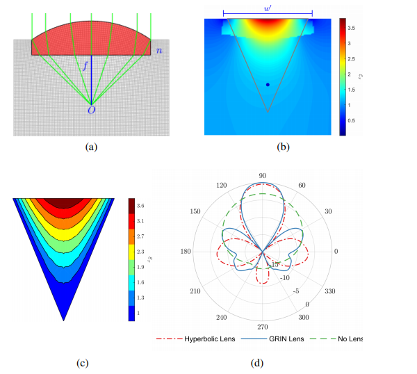
(a) Hyperbolic lens. (b) Permittivity map of transformed GRIN lens
overlaid with outline of octagonal sector. (c) Discretized permittivity values of
lens sector. (d) Radiation patterns from original hyperbolic lens, GRIN lens,
and waveguide port on its own

The researchers rotated the GRIN lens segment through 45°. It was copied seven times, allowing the team to create a comprehensive octagonal lens—alternating between beams spanning the whole 360° azimuth plane.

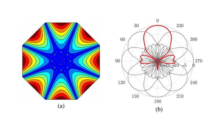
(a) The full octagonal graded dielectric lens with 8 individual segments – the feed points are shown in green. (b) The 2D radiation patterns from each segment at 5.8 GHz.

The octagonal lens featured eight directive beams, with crossover points displayed at a 22.5° offset from the center of each segment.

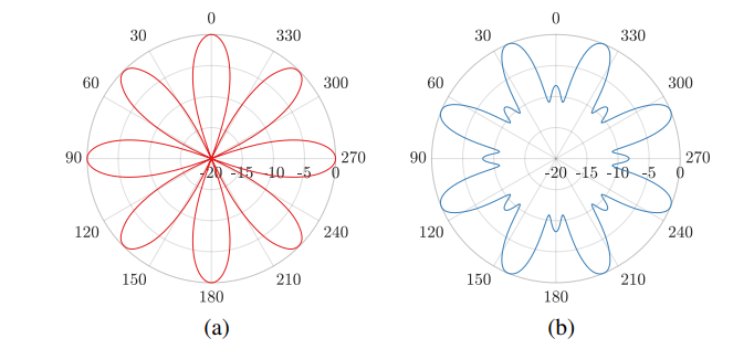
Radiation patterns of the 2D 8-sector lens with multi-port excitation. (a) Anti-phase excitation. (b) Equal-phase excitation.

“One of the drawbacks of phased antenna arrays is achieving the required phase and amplitude weightings required to each of the antenna elements, due to complexity, cost, power consumption and system losses,” explained the researchers. “Here however, the different radiation pattern combinations presented can be achieved through simple switched feeding networks.”

For 3D printing, the research team used a standard white ABS, along with ABS-400—both required to achieve necessary permittivity’s of the discretized lens.

The required fill factor for achieving different effective permittivities of the octagonal lens.

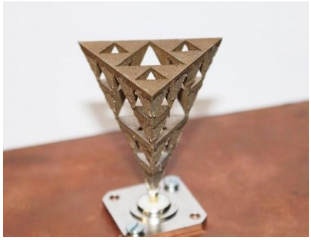
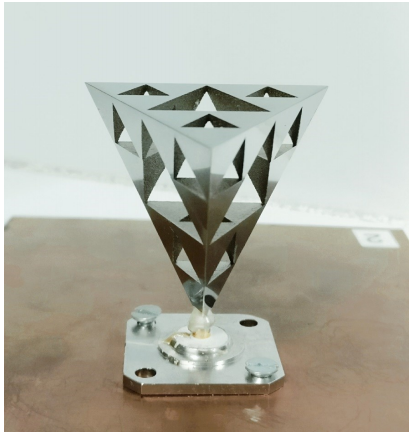
A 3D printed model of an antenna was fabricated via two different printing jobs, with the interior part of the lens made with standard ABS and six different sectors—and the second part made with ABS400.

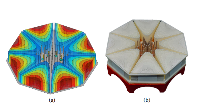
Full 3D antenna structure. (a) CAD model of 3D lens. (b) Photograph of 3D printed lens prototype with embedded feeding structure positioned on a metallic ground plane.

The GRIN lens was 3D printed on an Original Prusa i3 MK3 3D printer, with SMA connectors soldered to the side in feed point areas.

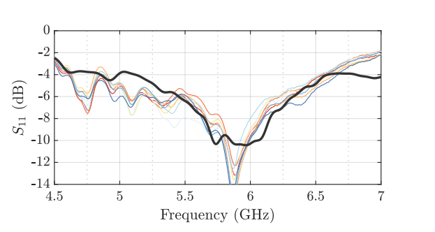
Input response of each of the feeding monopoles of the octagonal GRIN lens. The dark grey line shows the simulated data and coloured lines represent measured data of each port.

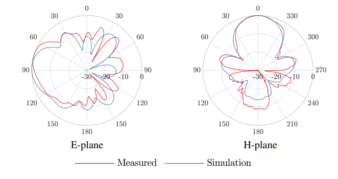
Measured and simulated E and H plane radiation patterns of a single
sector of the octagonal GRIN lens at 5.8 GHz.

“The lens was also able to radiate with an omnidirectional pattern, despite the directive nature of each individual sector,” concluded the researchers.

“The proposed antenna would be suitable for application in a MANET radio to be mounted on a mobile terminal when directive beams are required for interference mitigation and targeted communications.”

What do you think of this news? Let us know your thoughts! Join the discussion of this and other 3D printing topics at 3DPrintBoard.com.

[Source / Images: ‘Multi-Beam Graded Dielectric Lens Antenna from Multi-Material 3D Printing’]

The post Multi-Material 3D Printing for the Dielectric Lens Antenna appeared first on 3DPrint.com | The Voice of 3D Printing / Additive Manufacturing.

5G Networks Benefit from 3D Printed Multiple Input Multiple Output (MIMO) Antennas

As 3D printing continues to offer a host of benefits in the manufacturing of components like antennas, researchers Shaker Alkaraki and Yue Gao explore new applications, outlining their findings in the recently published ‘mm-Wave Low Cost MIMO Antennas with Beam Switching Capabilities Fabricated Using 3D Printing for 5G Communication Systems.’

One of the greatest advantages 3D printing and additive manufacturing processes offer is the potential to save exponentially on the bottom line in manufacturing certain parts—as well as being able to create them on demand and in many cases, much faster than by conventional methods. In this study, the authors investigate 3D printing of prototypes for multiple input multiple output (MIMO) antennas for 5G and millimeter-wave (mm-wave) applications.

With comprehensive standardization in place by 2020, 5G wireless technology for mobile technology is meant to expand in capacity enormously—by several hundred times over in comparison to previous processes, as it will be used over several frequency bands. So far, most countries have agreed with the proposal to use the following millimeter-wave (mm-wave) frequencies:

  • 24 GHz to 29.5 GHz
  • 37 GHz to 42.5 GHz
  • 2 GHz to 48.2 GHz
  • 64 to 71 GHz

Along with speed and affordability, 3D printing also allows the researchers to develop complex shapes; in this case, however, the process is more effective when used with new metallization techniques that are significantly lower in cost. In the MIMO system, multiple antennas are to be used, although there are challenges such as signal losses in higher atmospheres and high cost for system components.

“The attenuation of the signal at mm-wave mainly depends on the propagation distance, weather conditions and operating frequency,” stated the authors. “Shadowing is another important source of signal losses.”

The goal is to 3D print high-performance antennas that are steerable and more efficient but without the typically associated high expense.

The schematic of the proposed single element antenna. (a) Cross section of front view, (b) top view, (c) bottom view, and (d) perspective view.

The MIMO antenna prototypes developed for this study are:

  • Compact in design, measuring 2×2 and 4×3
  • More affordable
  • More efficient
  • Offers beam-switching abilities without phased array technology

The dimension of the proposed single element antenna

The schematic of proposed antenna with wall on its side. (a) Front view and (b) perspective view.

The antennas are comprised of two main parts:

  • Feeding structure – microstrip made up of mini-smp ground plane/pad, vias and transmission line fabricated using RO4003C substrate with a dielectric constant of 3.38.
  • Radiating structure – the 3D printed component, made up of a central slot surrounded by a rectangular cavity and two corrugations.

Creating both an asymmetric electric field and asymmetric surface current, one side of the antenna features a metallized wall. These elements steer the antenna beam, dependent on the wall height. The researchers note that ‘further increment within the wall height’ increases gain up to the point of saturation.

The relationship between wall height (?ℎ), directivity and beam direction at 28 GHz. (? = 10.71 ??)

While the smaller antenna is made up of four elements providing radiation in the boresight direction, the larger prototype offers six elements just for providing radiation—and then another six for steering.

The effect of wall height (?ℎ) on the radiation patterns of the antenna. (a) 2D radiation patterns of H-plane (y-z plane) for different wall height in ??, (b) 3D radiation patterns of the antenna with no wall ?ℎ = 0 ??, (c) 3D radiation pattern for ?ℎ = 4.5 ??, (d) ?ℎ = 11 ?? and (e) ?ℎ =25 ??.

“The beam of the 4 × 3 MIMO is steered mechanically through introducing a metallic wall with different height on the side of the radiating single element structure. The sidewall creates asymmetric electric field on the surface of the antenna, which reflects the beam of the antenna to the opposite direction.”

“The proposed sidewall is able to steer the beam of the MIMO up to 30° in the elevation plane. Finally, the performance of the proposed MIMO antennas are measured and found to operate as predicted by the numerical simulation tool,” concluded the authors.

3D printing is often a catalyst for greater innovation in creating parts like antennas, encouraging new concepts and expansion of traditional applications as researchers bring forth new projects featuring antennas for biomedical monitoring, polymer antennas for SAR systems, nanoantenna arrays, and more.

What do you think of this news? Let us know your thoughts! Join the discussion of this and other 3D printing topics at 3DPrintBoard.com.

[Source / Images: ‘mm-Wave Low Cost MIMO Antennas with Beam Switching Capabilities Fabricated Using 3D Printing for 5G Communication Systems’]

The post 5G Networks Benefit from 3D Printed Multiple Input Multiple Output (MIMO) Antennas appeared first on 3DPrint.com | The Voice of 3D Printing / Additive Manufacturing.

London: 3D Printing the Double-Ridged Horn Antenna for Biomedical Monitoring

Researchers are looking into ways to optimize biomedical monitoring, with their results outlined in ‘A 3D Printed High-Dielectric Filled Elliptical Double-Ridged Horn Antenna for Biomedical Monitoring Applications.’ Seeking to make further impacts in the field of medical science, the team from Queen Mary University of London has 3D printed an innovative device for sensing applications with wireless technology—based on ultra-wideband devices initially created for short-range wireless communications.

The in-house measurement setup based on the open-ended coaxial probe technique, used for the characterization of the dielectric materials.

Created to work within UK Communications Industries (Ofcom) and the Federal Communications Commission (FCC) regulation of UWBs, the new device has been found to offer depth suitable for penetration in scanning skin, muscle, and fat, with signals able to sense layer thicknesses. Wide-band technologies are often used for short-range communication due to:

  • Low power
  • High data rates
  • Multipath immunity
  • Simultaneous ranging and communication

While this type of antenna is not new, the use of 3D printing is novel. The double-ridged horn has been a topic of research over the years for researchers because of the benefits, leading to a more effective answer to refining accuracy in biomedical scanning. And while 3D printing can offer greater affordability in many cases, here the research team was concerned about cost-prohibitive fabrication, so they compared materials, ultimately settling on in-house 3D printing with ABS.

The shape of the horn allows for better operation overall, and the high dielectric material allows for a miniaturized design that also reduces reflection and is both easy and affordable to make. With an extension, the scientists were able to expand on the antenna and prevent signal-overlapping issues.

Modeled extended EDRH antenna with the structural labels and the dimensions for the extended section.

“The optimal approach is to extend the outer aperture of the antenna, and to define, the antenna outer aperture length, so the scanning tissue area can be placed in the far-field region,” stated the researchers. “This has added more complexity to the fabrication and realization of the device with the increased cost, but on the other hand, it has made it more stable in its operation, and free of any destructive interference signals and noise.”

The team used the Stratasys Objet30 Prime 3D printer for creating their prototype, finishing it with clear Vero polyethylene, stating that hardware and materials not only offered high resolution, accuracy, and conductivity, but also affordability in fabrication.

Measurements were found to be accurate also, as they addressed concerns regarding individual and other influences like scanning areas and layer structure but concluded that there should be very little variance between ‘permittivity and thickness.’ If an impact on the results was noted, the researchers explained that added calibration measures could be taken with an open-ended probe, with software producing the results.

(a) 3D-printed EDRH antenna using the polyethylene material. (b) 3D-printed EDRH antenna, as conductive-painted and fed with a semi-ridged SMA connector. (c) 3D-printed EDRH antenna filled with the high-dielectric mixture.

“This design incorporates the extension for locating the antenna in the far-field region of the scanning area, for the plane-waves to penetrate more directly into the body. Moreover, the antenna can operate at the lower frequency band of WB to exhibit a better penetration depth and impedance matching using the mixture for the biomedical application, which monitoring very deep inside the body is the main objective of the system,” concluded the researchers at the end of their study.

3D printing has offered much greater expansion opportunities for scientists and engineers interested in creating better devices for sensing and monitoring, from automotive sensors to electrochemical sensing, and 3D printed models for better monitoring.

What do you think of this news? Let us know your thoughts! Join the discussion of this and other 3D printing topics at 3DPrintBoard.com.

[Source / Images: ‘A 3D Printed High-Dielectric Filled Elliptical Double-Ridged Horn Antenna for Biomedical Monitoring Applications’]


The post London: 3D Printing the Double-Ridged Horn Antenna for Biomedical Monitoring appeared first on 3DPrint.com | The Voice of 3D Printing / Additive Manufacturing.

Student Takes A Look at Several Metal 3D Printed Antennas for Thesis Paper

In a thesis entitled “Design of Microwave Components using Direct Metal Laser Sintering,” a Waterford Institute of Technology student named Deepak Shamvedi discusses using 3D printing to fabricate several microwave components, including the first-ever 3D printed metal Sierpinski gasket antenna, with multiple resonance characteristics. Shamvedi chose the Sierpinski gasket antenna because of its complexity, aiming to “push the limits of 3D metal printing.”

The antenna was 3D printed using the EOSINT M280 machine and a titanium alloy called Ti-6Al-4V.

“Following the rules of 3D printing, one should acknowledge that even though the Sierpinski fractal design may look simple, but it is complex at the same time,” states Shamvedi. “It consists of an arrangement of stacked pyramids one-upon-another, to form a 3D geometry. A rectangular copper clad PCB ground plane, of 160 mm x 100 mm, with 1 mm thickness, has been used to serve as a finite ground plane to the printed antenna.”

Because the 3D printed version of the antenna could not be realized with infinitely small joints, Shamvedi had to print it in an upside down orientation with a minimum of 1.90 mm base diameter (0.95 mm base radius). This value was chosen to achieve the 3D design without any metal drooping. The base diameter also needed to be big enough to facilitate soldering if needed. The base diameter of the antenna formed a ring-like shape, due to which the effect of the RF performance of the antenna, from increasing or decreasing the width of the ring, has been named the “ring width effect.”

Support structures were required; in order to make them easier to remove, Shamvedi added small holes in the CAD design of the supports. Once the antenna was 3D printed, it underwent a rigorous post-processing routine to remove the supports and reduce the surface roughness of the component. The antenna was then mounted onto feeding circuitry for RF measurements, which were carried out after each stage of post-processing, including wet blasting and polishing, to assess the affect of the surface roughness on the antenna’s performance.

“From the results obtained, increased surface roughness increases the random scattering of electromagnetic waves; therefore, increasing RF resistance, which further reduces the gain of the antenna,” explains Shamvedi. “The antenna RF performance was measured and found to be in good agreement with simulation results, in terms of bandwidth and radiation characteristics.”

Experimental prototype of a monocone antenna

Shamvedi also 3D printed a monocone antenna and integrated an N-type feed onto it to create a monolithic structure. 3D printing, he explains, produces fine detail and robust components with low surface roughness. A monolithic structure can also offer better mechanical properties over glue or solder. Despite some challenges, Shamvedi was able to produce a working prototype of a 3D printed antenna, and the measured RF results for the antenna were found to be in good agreement with the CST simulation results.

Shamvedi then compared the performance of three metal 3D printed antennas to that of polymer ones. A metal 3D printed inner lattice antenna possessed higher strength-to-weight ratio than a metal-coated polymer antenna. He also investigated the effects of surface roughness on a 3D printed metal horn antenna, and explored 3D printing as a means to improve the performance of an X-band horn antenna, with the primary goal of side-lobe reduction. Finally, he 3D printed an artificial dielectric lens for applications including 5G.

Discuss this and other 3D printing topics at 3DPrintBoard.com or share your thoughts below.