3D Printing Better Antennas for Millimeter-Wave Multi-Beam Applications

In the recently published ‘A 3D Printed Compact High-Efficiency Magneto-Electric Dipole Antenna Sub-Array for Millimeter-Wave Multi-Beam Applications,’ authors Liyue Zhao, Yujian Li, and Junhong Wang—all from Institute of Lightwave Technology, Beijing Jiaotong University—explore the fabrication of a new 3D printed 2 × 2 multi-beam magneto-electric (ME) dipole metallic antenna subarray. In this study, the authors proposed a topology of a beamforming network, comprised of four 3-dB couplers that are filled with air.

Antennas are significant to many applications around the globe today, but specifically to the arena of mobile communications. Many different types of hardware and power consumption are cost-prohibitive though on the larger scale, as each element must be connected with a radio frequency (RF) chain; however, hybrid analog and digital beamforming are promising for decreasing the amount of RF chains. Passive multi-beam antennas are becoming more popular also as they operate at the millimeter wave and are also affordable to create. The authors point out that beamforming networks are restricted in some cases, and also have other common issues:

“Recently, several modified beam-forming methods based on the multi-layered substrate-integrated geometries have been investigated to increase the array size and to enhance the achievable number of radiation beams,” said the authors. Unfortunately, due to the existence of the dielectric loss, the insertion loss of the substrate-integrated beamforming networks increased significantly with the size of the array. As a result, the reported multi-beam arrays suffered from a low radiation efficiency. In addition, the beamforming network with a size not larger than the radiating aperture was still not easy to fulfill, especially for the array with the two-dimensional multi-beam radiation.”

Ultimately, 3D printing offers new options—and benefits for fabrication of antennas. While bandwidth and high gain features have been created though at both the microwave and millimeter-wave frequencies, millimeter-wave multi-beam antenna array has ‘seldom’ been touched on in research.

Topology of the proposed beamforming network feeding the two-dimensional multi-beam ME-dipole subarray.

For this study, the researchers suggest a 2×2 two-dimensional multi-beam subarray, with four 3-dB couples. This topology offsets challenges with the multi-layers planar geometry, and allows for compact size. Also, with two sets of couplers at the same height, the beamforming network size is shortened also—when compared to more basic topologies. The metallic 2×2 ME-dipole antenna array is made up of four planar metal patches which work together as a set of electric dipoles. The ground plane relates to the four vertical walls in an L-shape.

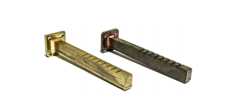
Geometry of the 2×2 ME-dipole array with the tapered waveguide connections. (a) Perspective view, (b) top view, (c) perspective view of the tapered waveguide connections.

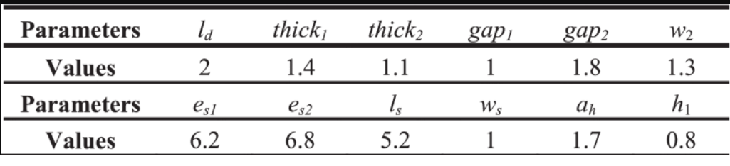
Dimensions of the Proposed 2×2 ME-Dipole Antenna Array With the Tapered Waveguide Connections (Units: mm)

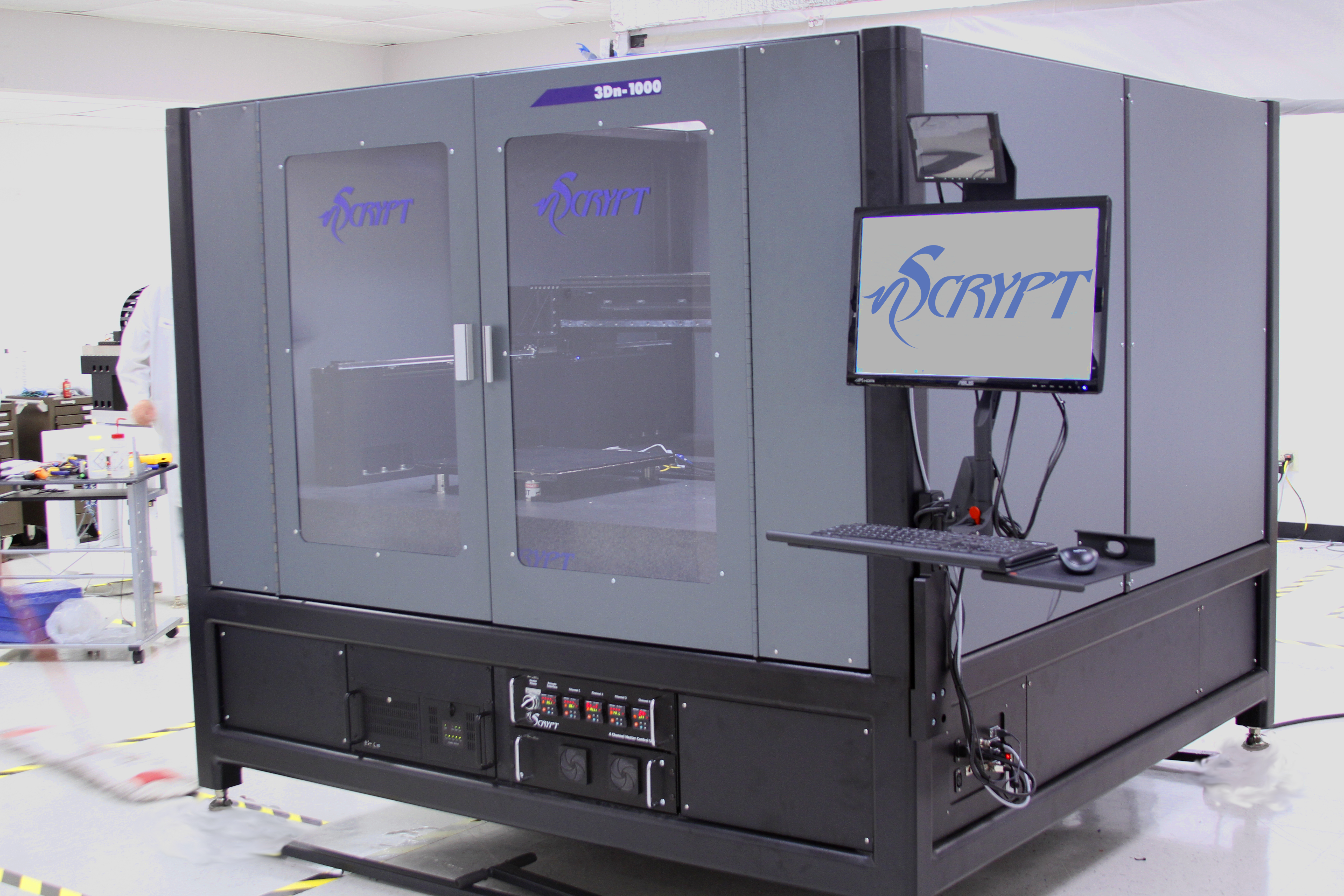
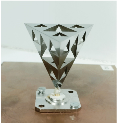
The research team created a prototype via metal 3D printing with aluminum alloy AlSi10Mg powder.

“In terms of the bandwidth, due to the wideband performance of the aperture-coupled ME-dipole elements, the operating bandwidth of about 20% can be achieved by the array in and this work, which has superiority in comparison with the counterparts in [12] and [23]. More importantly, as the dielectric loss is prevented completely in the proposed beamforming network composed of the air-filled waveguides, a remarkable improvement in the radiation efficiency can be observed in this work. As a result, the 3D printed multi-beam subarray has the gain of about 1 dB higher than the reported results,” concluded the researchers.

“The proposed 3D printed multi-beam subarray can be utilized for designing the sub-array level beam tuning array with a large size, which is valuable to the millimeter-wave multiple-input multiple-output applications.”

The technology of 3D printing has been associated with many different innovations regarding the design of antennas, from the nanoantenna to those created for SAR systems, and so much more. What do you think of this news? Let us know your thoughts! Join the discussion of this and other 3D printing topics at 3DPrintBoard.com.

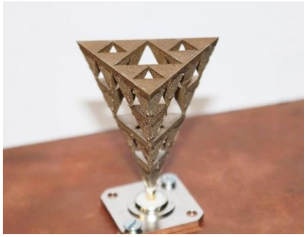
Photograph of the prototype of the proposed 3D printed 2×2 multi-beam subarray.

[Source / Images: ‘A 3D Printed Compact High-Efficiency Magneto-Electric Dipole Antenna Sub-Array for Millimeter-Wave Multi-Beam Applications’]

The post 3D Printing Better Antennas for Millimeter-Wave Multi-Beam Applications appeared first on 3DPrint.com | The Voice of 3D Printing / Additive Manufacturing.

German Aerospace Center: Creating 3D Printed Polymer Antennas for Synthetic Aperture Radar (SAR) Systems

Thesis student Jan Reifenhäuser at the Koblenz University of Applied Sciences explores the uses of 3D printing in creating improved antennas for multiple applications, outlined in ‘Investigation of a Plastic Printed Slotted Waveguide Antenna for Airborne SAR Applications.’ Reifenhäuser’s interest in creating antennae are directly related to a new project at the German Aerospace Center, as they begin working with synthetic aperture radar (SAR) technology in Ka-band—more specifically, the Ka-band PolInSAR system.

Due to requirements for excellence in mechanical accuracy, 3D printing was chosen as the manufacturing method with temperature-resistant plastic. The researchers involved in the project created two different antenna prototypes with plastic, and brass. Because the German Aerospace Center is so vast, boasting numerous different institutes at 20 different German sites, their resources are considerable in research for applications such as:

  • Aeronautics
  • Space
  • Energy
  • Transport
  • Digitization
  • Security
  • Space Administration

TanDEM-X and TerraSAR-X SAR satellites, flying in formation to create an interferometric system.

In the Microwaves and Radar Institute, however, they focus solely on researching new technologies related to radar, remote sensing, and specifically for this study, airborne and satellite-based radar systems with synthetic aperture—used for better accuracy in providing data—from space, for example. SAR interferometry can act as an extension, with two different sensors taking images of the same thing. The altitude of objects being monitored can be precisely figured, which is helpful in mapping applications. Radar signals can also be used to obtain greater amounts of data about features such as surface condition.

“When reflected on ground, the polarization may change depending on the reflecting surface,” states Reifenhäuser. “This change is detected upon receiving the echo and conclusions can be drawn about the surface. This procedure is called polarimetry.”

Currently, the institute uses research aircraft (like the Do228-212 aircraft) for compiling SAR images, with their interest in such applications and the field of satellite-based systems increasing—and expanding toward Ka-band SAR systems as there is growing interest worldwide too. The Ka-band is distinguished by its shorter wavelength, and the ability to use ‘lower penetration depth’ into volume. This lends its uses to applications requiring precision, like the weather and climate research.

DLR’s Do228-212 research aircraft with F-SAR system.

So far, however, scientists have had limited experience dealing with Ka-band SAR systems including single pass interferometric or polarimetric capabilities—there are increasing numbers of Ka-band hardware components becoming available to consumers through the commercial market though. In creating their Ka-band PolInSAR Demonstrator, DLR steps into the realm of aircraft-based Ka-band PolInSAR systems.

The 3D printed antenna had to be created with the following considerations:

  • Center frequency of 35.75 GHz
  • Bandwidth of at least 500 MHz
  • Beam-width of 30° in elevation and 5° in azimuth
  • Altitude range of 0 m up to 6000 m (the military test standard)
  • Polarimetric operation

Testing was completed both with simulated exercises and physical measurement, with a brass antenna serving as a reference point for the 3D printed version. Both devices were tested at 21 °C in DLR’s compact test range (CTR), leaving the researchers to further to investigate ‘influence of temperature.’ Stating that it is advisable for using several single radiators to better define radiation characteristics, the researchers combined several of them together into a ‘group antenna,’ achieved by creating ‘slots’ in a waveguide wall.

Ultimately, the Ka-band PolInSAR system consists of multiple antennas set up to encourage beam forming, with the horizontal and vertical antennas alternated, resulting in a very small distance between polarizations. The researchers outsourced 3D printing of one prototype, while the other was milled from brass using traditional manufacturing methods. The 3D printed antenna was made of plastic but finished with a layer of copper. Thermal expansion had the greatest impact on both antennas—but the researchers also found very small differences between antenna gain and input reflection.

The team also noted that while testing the prototypes for the impacts of temperature change, they noticed a transformation in the signal phase. They also noted higher error in phase assignment as increased numbers of elements were arranged in the waveguide array. Ultimately however, similar antennas set at different frequency ranges exhibited the same character adjustments.

“Looking at the single element of the antenna array, it can be said that the small ascertained pointing error is compensated by the symmetry of the antenna due to the central feed,” concluded the researchers. “Printed plastic is therefore suitable as material for the antenna array of the Ka-band PolInSAR system.”

Some industries have actually been using 3D printing for decades, mainly for prototypes, but in recent years, many more functional parts are being fabricated and relied on—whether created in plastic, metal, or other materials, from conformal phased array antennas to sensors and wearables and even wearable antennas. Find out more about antennas being 3D printed by the German Aerospace Center here.

What do you think of this news? Let us know your thoughts; join the discussion of this and other 3D printing topics at 3DPrintBoard.com.

[Source / Guide: ‘Investigation of a Plastic Printed Slotted Waveguide Antenna for Airborne SAR Applications’]

Array of horizontally and vertically polarized slotted waveguide antennas.

Antenna prototypes made of brass (left) and plastic (right).

US Air Force Awards nScrypt Research Company Contract for 3D Printed Conformal Phased Array Antenna Project

Florida-based nScrypt, which manufactures industrial systems for micro-dispensing and 3D printing, is already seeing its technology used for military applications with the US Army. But now the US Air Force has jumped on the nScrypt bandwagon as well. Sciperio, nScrypt’s research and development think tank, was awarded a second phase contract by the Air Force for its 3D printed conformal phased array antennas project.

Sciperio specializes in cross-disciplinary solutions, and developed technology that was commercialized by nScrypt under the Mesoscopic Integrated Conformal Electronics (MICE) program with the Defense Advanced Research Projects Agency (DARPA). In 2016, the research group developed the first fully 3D printed phased array antenna for the Air Force, and has continued attempting to conform these antennae to complex surfaces, which would allow advanced communication technology to be added directly into an aircraft or vehicle body.

A phased antenna array uses both constructive and destructive interference to individually control each element’s signal phase and precisely “aim” the signal, instead of radiating it out in multiple directions. This feature is critical in terms of military applications, as it makes communications more secure and less likely to be intercepted by the enemy.

“Directly printing active phased array antennas on curved surfaces will provide unique capabilities to the DoD (Department of Defense), but the ultimate goal is to do this at a fraction of the cost of traditionally manufactured arrays,” said Casey Perkowski, Sciperio’s Lead Developer on the project. “This will allow the DoD to use these antennas in a more ubiquitous manner and this will translate to commercial applications.”

Not only is this technology important for the military, but it’s also vital to nScrypt’s vision of fully 3D, non-planar next generation electronics that will either conform to, or be embedded in, an object’s structure. At present, PCBs are placed into boxes and connected with unwieldy wiring harnesses; nScrypt is working toward a future where the PCB, box, and harness will be depleted so electronics can be smaller, less expensive, more lightweight, and integrated directly into the structure.

nScrypt’s Direct Digital Manufacturing platform, called the Factory in a Tool (FiT), enables the company’s vision of integrated electronics. The FiT has multiple tool heads, including nScrypt’s nFD for Material Extrusion, the SmartPump for Micro-Dispensing, nMill for micro-milling, and nPnP for pick and place of electronic components, which are placed on a high-precision (1 micron accuracy) linear motion gantry. Multiple cameras allow for automated inspection and computer vision routines, while a point laser height sensor maps surfaces.

All of these features add up to allow for successful conformal printing, or micro-dispensing, onto objects. Because everything is combined in one platform, manufacturers of complex structural electronics can create them with the press of a button.

nScrypt and Sciperio bring an additional advantage to the table in their projects for the DoD: high-precision motion and micro-dispensing excels. Each dimension in RF electronics is critical, and if a line is off by even the smallest fraction, the circuit’s performance is ruined, and so is that of the device with which it’s being used.

But the previously mentioned SmartPump offers picolitre volumetric flow control, while the nFD extruder provides precision deposition and the motion platform has 0.5 micron repeatability. This means that nScrypt’s unique platform can produce both conductive and dielectric features to high tolerances…ensuring successful RF circuits for the DoD.

[Image: nScrypt]

The goal of the Air Force project that nScrypt and Sciperio are working on is to produce an 8 x 8 element array on an ellipsoidal surface. The University of South Florida is a subcontractor on the project, as it previously worked with Sciperio back in 2016 to develop the first fully 3D printed phased array antenna, and will once again support antenna design, simulation, and testing.

Discuss this and other 3D printing topics at 3DPrintBoard.com or share your thoughts below. 

Student Takes A Look at Several Metal 3D Printed Antennas for Thesis Paper

In a thesis entitled “Design of Microwave Components using Direct Metal Laser Sintering,” a Waterford Institute of Technology student named Deepak Shamvedi discusses using 3D printing to fabricate several microwave components, including the first-ever 3D printed metal Sierpinski gasket antenna, with multiple resonance characteristics. Shamvedi chose the Sierpinski gasket antenna because of its complexity, aiming to “push the limits of 3D metal printing.”

The antenna was 3D printed using the EOSINT M280 machine and a titanium alloy called Ti-6Al-4V.

“Following the rules of 3D printing, one should acknowledge that even though the Sierpinski fractal design may look simple, but it is complex at the same time,” states Shamvedi. “It consists of an arrangement of stacked pyramids one-upon-another, to form a 3D geometry. A rectangular copper clad PCB ground plane, of 160 mm x 100 mm, with 1 mm thickness, has been used to serve as a finite ground plane to the printed antenna.”

Because the 3D printed version of the antenna could not be realized with infinitely small joints, Shamvedi had to print it in an upside down orientation with a minimum of 1.90 mm base diameter (0.95 mm base radius). This value was chosen to achieve the 3D design without any metal drooping. The base diameter also needed to be big enough to facilitate soldering if needed. The base diameter of the antenna formed a ring-like shape, due to which the effect of the RF performance of the antenna, from increasing or decreasing the width of the ring, has been named the “ring width effect.”

Support structures were required; in order to make them easier to remove, Shamvedi added small holes in the CAD design of the supports. Once the antenna was 3D printed, it underwent a rigorous post-processing routine to remove the supports and reduce the surface roughness of the component. The antenna was then mounted onto feeding circuitry for RF measurements, which were carried out after each stage of post-processing, including wet blasting and polishing, to assess the affect of the surface roughness on the antenna’s performance.

“From the results obtained, increased surface roughness increases the random scattering of electromagnetic waves; therefore, increasing RF resistance, which further reduces the gain of the antenna,” explains Shamvedi. “The antenna RF performance was measured and found to be in good agreement with simulation results, in terms of bandwidth and radiation characteristics.”

Experimental prototype of a monocone antenna

Shamvedi also 3D printed a monocone antenna and integrated an N-type feed onto it to create a monolithic structure. 3D printing, he explains, produces fine detail and robust components with low surface roughness. A monolithic structure can also offer better mechanical properties over glue or solder. Despite some challenges, Shamvedi was able to produce a working prototype of a 3D printed antenna, and the measured RF results for the antenna were found to be in good agreement with the CST simulation results.

Shamvedi then compared the performance of three metal 3D printed antennas to that of polymer ones. A metal 3D printed inner lattice antenna possessed higher strength-to-weight ratio than a metal-coated polymer antenna. He also investigated the effects of surface roughness on a 3D printed metal horn antenna, and explored 3D printing as a means to improve the performance of an X-band horn antenna, with the primary goal of side-lobe reduction. Finally, he 3D printed an artificial dielectric lens for applications including 5G.

Discuss this and other 3D printing topics at 3DPrintBoard.com or share your thoughts below.


3D Printing 5G Telecommunication Technology

The telecommunications industry is currently front page news including the AT&T/Timewarner acquisitions, the pending Fox acquisition by Comcast or Disney and a new CEO at Verizon who is a technologist with a focus on 5G. Once the current merger activity further settles, we anticipate a new, focused, and competitive telecomm industry. The use of additive manufacturing in the telecommunications sector has introduced new solutions for advancements in current technology. Telecommunication components are expensive to prototype, manufacture and install while spare parts are also significant costs to many new projects and existing ones. Using additive manufacturing, parts such as electrical components that have arbitrary and geometrically intricate shapes/sizes can be easily prototyped and integrated onto printable circuits. Antennas, sensors and power stations for IT departments, telecommunication companies, cable operators, and related companies are now being deployed with 3D printed parts as the technology becomes more widely accepted in the sector. 3D printing components for telecommunication purposes is eligible for Research and Development tax credits.

The Research & Development Tax Credit

Enacted in 1981, the now permanent Federal Research and Development (R&D) Tax Credit allows a credit that typically ranges from 4%-7% of eligible spending for new and improved products and processes. Qualified research must meet the following four criteria:

  • Must be technological in nature
  • Must be a component of the taxpayer’s business
  • Must represent R&D in the experimental sense and generally includes all such costs related to the development or improvement of a product or process
  • Must eliminate uncertainty through a process of experimentation that considers one or more alternatives

Eligible costs include US employee wages, cost of supplies consumed in the R&D process, cost of pre-production testing, US contract research expenses, and certain costs associated with developing a patent.

On December 18, 2015, President Obama signed the PATH Act, making the R&D Tax Credit permanent. Beginning in 2016, the R&D credit can be used to offset Alternative Minimum Tax, for companies with revenue below $50MM and for the first time, pre-profitable and pre-revenue startup businesses can obtain up to $250,000 per year in payroll taxes and cash rebates.

3D Printing Uses in Telecommunications

MIMO

MIMO antennas (multiple input, multiple output) are antenna technology for wireless communications in which communication circuits are combined to minimize errors and optimize data speed. Recently, communications manufacturers have been experimenting with 3D printing the powerful antennas. Utilizing a high-resolution stereolithography 3D printer, the printing process is entirely precise as it is capable of printing 27.2 x 27.2 x 17 mm antennas that can be completed within half an hour. The printed antenna is made of a photosensitive resin, ensuring all its surfaces are metalized and conductive, further enhancing frequency characteristics.

Orange

Orange is one of the world’s leading telecommunications operators; headquartered in France, they provide to 200 million mobile customers and 18 million fixed broadband customers. Orange is working to provide clean renewable energy to millions of on-the-grid users as well as expanding to those off the grid through the use of 3D printed components optimizing many power sources such as wind turbines. Small wind turbines are being used to improve efficiency and optimize mobile connection performance but can be expensive to build in mass production. Orange adopted 3D printing to utilize for the wind turbines as they are printing blades that are significantly reducing the cost of the units, as well as improving performance to provide impacts to the lives of those living in energy poverty along with those currently already using energy solutions.

Optomec

Optomec is a 3D manufacturing company based in Albuquerque, New Mexico that specializes in printing solar cells, flexible electronics, organic electronics, and touchscreen components, among many other parts, and are now experimenting with 3D printing functional parts for a phone such as the antenna. 3D printing a phone antenna now provides phone companies flexibility in the design and allows for a reconfiguration of the whole production line. With the ability to mass produce small phone components such as an antenna with 3D printing, no longer will harmful solvents and materials be needed for such parts and it will even provide a less expensive solution for phone companies whose profit margins are already razor thin.

Voxel8 Inc.

Voxel8 is a 3D manufacturing company that is adept at printing electronic components especially for telecommunications. The company from Somerville, Massachusetts has developed a 3D printer capable of printing one-piece, functioning electronic devices such as a smart phone. The printer creates digital manufacturing systems that can print numerous types of components such as antennas, electromagnetic coils or stacked integrated circuits, among many more. Though capable of printing whole pieces, some assembly is still required for installing batteries, sensors and resistors for which Voxel8 is working to develop new inks to print these parts. The company hopes to revolutionize the telecommunication industry and eventually eliminate the need for the painstaking task of thousands of human workers having to assemble the complex handheld devices we use every day.

Airbus Defence and Space

Airbus, the large aerospace company headquartered in Toulouse, France, is experimenting with metal 3D printing to develop critical parts for satellites used in telecommunications. Airbus is 3D printing metal waveguides used on telecom satellites which are crucial pieces that filter out unwanted radio frequencies and allow others to pass through. The additive manufactured parts provide improved performance while lowering production costs and excess waste and eliminating design constraints seen with traditional manufacturing techniques. The less bulky 3D printed waveguides are allowing for more waveguide components to be integrated onto satellites, greatly increasing the degree of functionality while delivering more capable telecom satellites that will soon change the landscape of how satellites are designed and developed.

Conclusion

Telecommunications is one of the most important aspects of everyday life; without it, data, information, messages, etc. would not be exchanged in a timely manner, if at all. Recent developments in 3D printing for the field have eliminated many of the limiting barriers that have prevented much of the technology from being utilized to full potential due to factors such as cost or feasibility to implement such methods. 3D printing is being used more than ever and telecom specializing companies are digging in to significantly improve upon 3D printing methods to continually provide solutions that will change much of daily life for the better.

Discuss this and other 3D printing topics at 3DPrintBoard.com, or share your thoughts below.


Charles Goulding and Ryan Donley of R&D Tax Savers discuss 3D printed telecommunications devices.