
Additive manufacturing (AM) is already making strong inroads into the injection molding industry due to its ability to reduce the cost and improve the performance of molds used in the process. What we are now starting to see is an increasing number of companies and services aimed specifically at leveraging AM and computer aided engineering to disrupt the injection molding market. One such company is Next Chapter Manufacturing (NXCMFG).
Prior to founding NXCMFG, Jason Murphy worked in the mold making industry, using traditional processes like CNC machines, milling and drilling to craft tooling for injection molding. He eventually established a mold making company that he ran for about 10 years before selling it. Murphy then moved onto the plastics side of the industry, where he worked in plastics processing for another 10 years. He believes that the mold making industry has become somewhat set in its ways, forgetting to look for innovation in the space. For that reason, he established NXCMFG.
NXCMFG is a tooling company that uses AM to produce metal inserts and tooling for use in plastic injection molding and metal die casting, as well as jigs, fixtures and other tools. While it may not perform high volume production itself, NXCMFG makes the parts that make the parts made through high volume production technologies. Clients range from small businesses to Fortune 500 injection molding companies.
The hardware consists of Farsoon metal Direct Metal Laser Sintering (DMLS) systems, which have the performance, resolution and the cost necessary for a relatively small businesses like Murphy’s to produce entirely new molds or inserts for existing molds. And, while typical projects consist of one-off prints, the firm typically builds multiple parts for multiple projects at a single time. According to Murphy, his is in the only company in the U.S. that is able to print H13 tool steel and 420 stainless steel using a metal DMLS process.
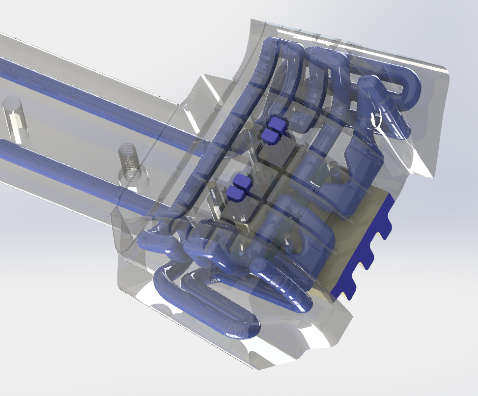
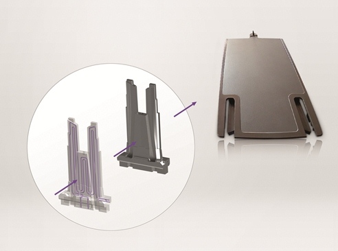
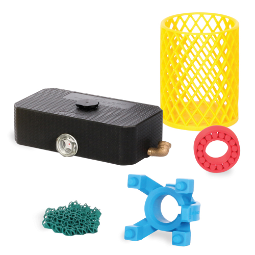
A mold with conformal cooling. Image courtesy of NXCMFG.
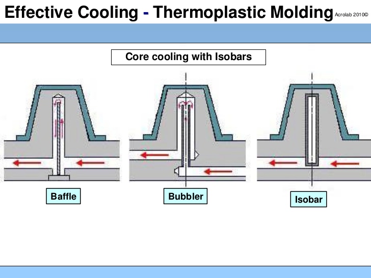
However, probably the most interesting aspect of NXCMFG’s work is the use of conformal cooling and generative design to optimize injection molds and inserts. Unlike traditional CNC processes used to integrate cooling channels into molds, NXCMFG is able to include channels that conform to the shape of the mold, which reduces the time it takes for the mold to cool and a new injection molding job to begin. According to Murphy, his company is able to introduce a 20 to 80 percent improvement in cycle time.
While conformal cooling is becoming increasingly deployed by a number of additive companies in the space, NXCMFG is designing cooling vents for molds. Murphy explained, “Before you inject the plastic in, there is air inside of the mold so that, when you inject the plastic, that air has to go somewhere. You can’t have a hole in the mold because all of the plastic would come out. So, you have these thin slots that are about one-third of the width of a human hair that all of that gas has to escape out of.”
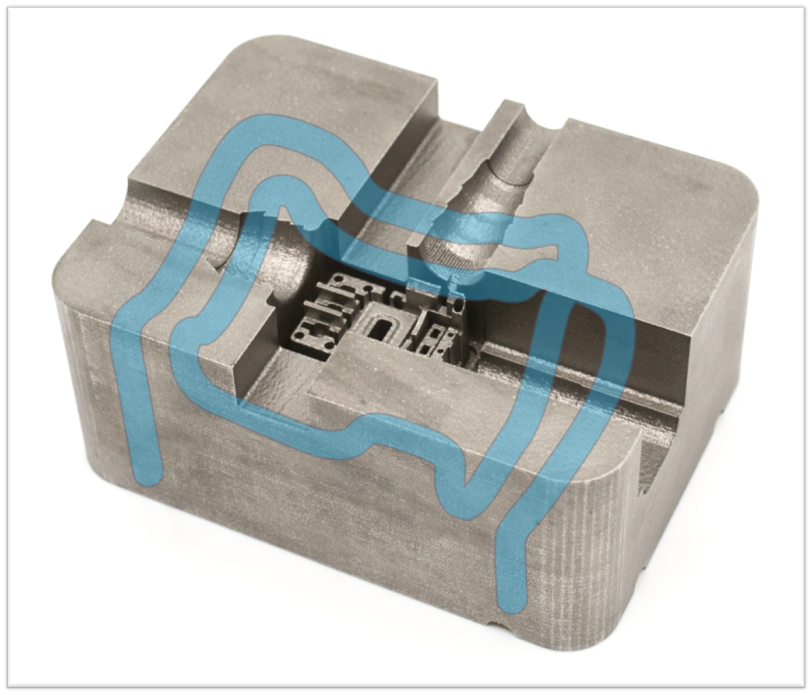
A mold with conformal cooling. Image courtesy of NXCMFG.
Using AM, Murphy’s company can incorporate slits that measure up to one-thousandth of an inch. Moreover, NXCMFG is working on new methods of design that actually change the density of the steel molds they are printing so that the areas in contact with the liquid plastic are porous like a sponge. This would result in quick and even gas displacement, as well as more rapid cooling for improved cycle times. The firm also uses generative design to reduce the weight of molds, resulting in organic-looking tooling with material only where it needs to be for proper strength and performance.
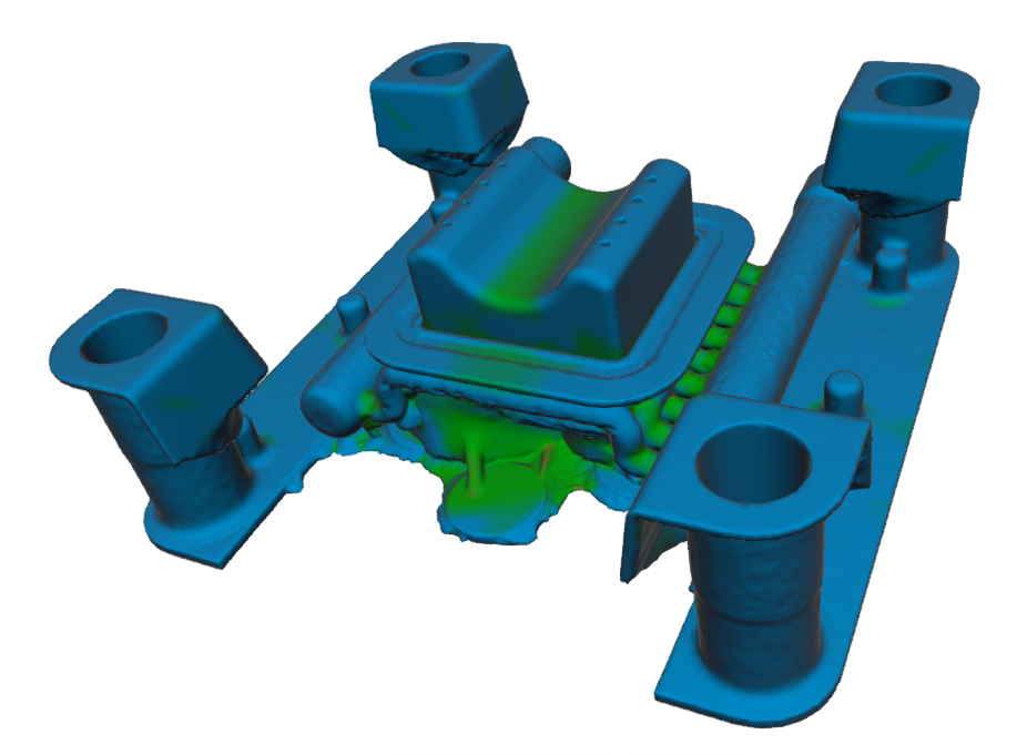
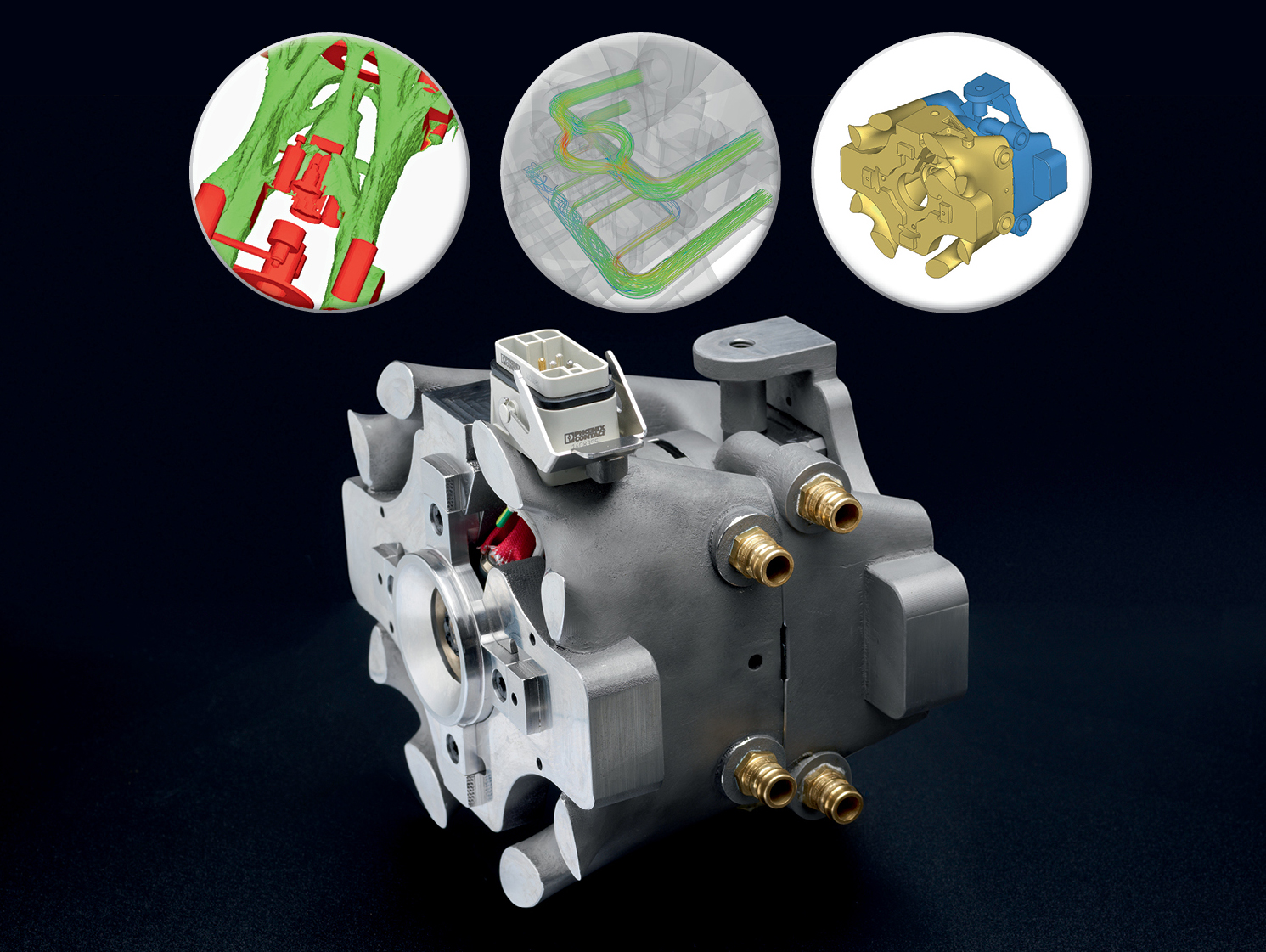
A generative design study. Image courtesy of NXCMFG.
NXCMFG isn’t only utilizing these unique design features in new molds, but also inserts that can be used to modify older tooling. Murphy’s team is able to incorporate cooling channels and venting into a single mold insert, placing a porous steel design alongside a cooling channel for maximum performance with legacy tooling. This saves customers the money that would be used for creating an entirely new mold
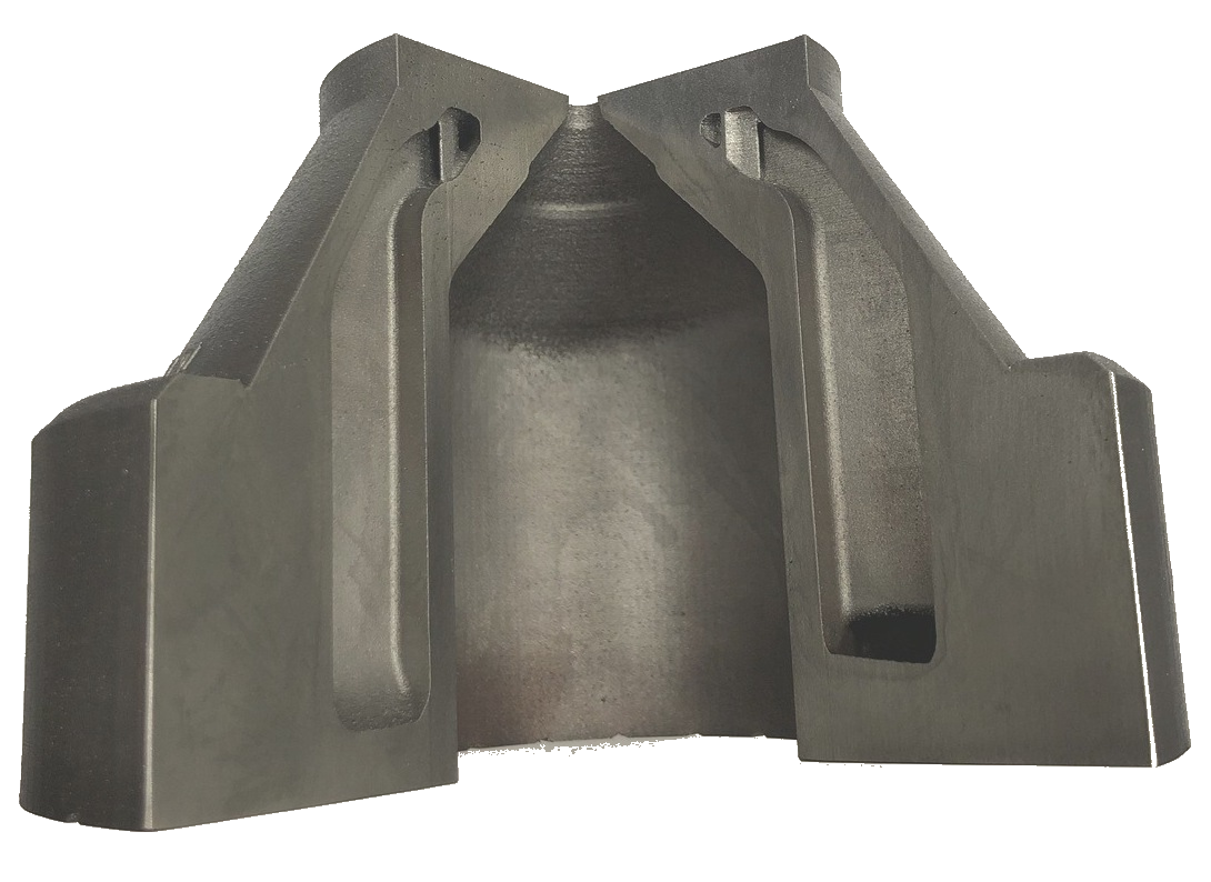
A 3D-printed insert. Image courtesy of NXCMFG.
All of these features end up being profitable for their customers in a variety of ways. By cutting cycle times, injection molders can make more parts more quickly, thus reducing machine hours and labor. The process also reduces plastic scrap because conformal cooling and venting reduces defects in plastic parts.
“We’re the only people in the industry 3D printing molds with a million shot guarantee. We offer a guarantee that says, ‘Look, our tooling is so robust that it’ll last a million cycles in production, which is industry standard for traditional tooling,” Murphy said.
What NXCMFG demonstrates is that the tooling sector is only beginning to feel the impact of AM. As one of the most innovative firms in the space, Murphy’s is ahead of the curve in terms of where molds are headed. By the time others follow suit, NXCMFG may be on to even newer and more unique methods for improving mass manufacturing practices.
The post Next Chapter Manufacturing: Redesigning Injection Molding with 3D Printing appeared first on 3DPrint.com | The Voice of 3D Printing / Additive Manufacturing.
 cements its status as a leading aluminium powder for additive manufacturing after breaking the critical 500 MPa UTS mark.


