FDM 3D Printing: Effects of Typical Parameters on Functional Parts

Ahmed Elkaseer, Stella Schneider, and Steffen G. Scholz delve further into the effects of parameters and settings on the quality of parts, releasing the details from their recent study in ‘Experiment-Based Process Modeling and Optimization for High-Quality and Resource-Efficient FFF 3D Printing.’

Reminding us that 3D printing was originally designed for rapid prototyping, centered around the work of engineers, the authors point out that users around the world are now also beginning to rely on such technology for ‘customized mass production of functional parts,’ due to a sufficient evolution of the processes; however, there is still much to be learned and improved. This is especially true as users continue to innovate within so many different applications, from automotive to aerospace to construction, and so much more.

A schematic of the fused filament fabrication (FFF, FDM, Material Extrusion) process.

This study focuses on FDM (FFF, Material Extrusion) 3D printing as the authors examine what is accurately depicted as ‘a large number of individually adjustable printing parameters,’ and why defects and problems so often occur. Noting that PLA is a popular material in 3D printing, enjoyed due to its more environmentally friendly nature and ease in use, the authors analyzed the following on a test structure:

  • Infill percentage
  • Layer thickness
  • Printing speed
  • Printing temperature
  • Surface inclination angle

CAD model of a test sample (10 mm × 46 mm × 46 mm).

Simplify3D was used as slicing software, with test samples 3D printed on the Zmorph 2.0 SX.

Zmorph 2.0 SX.

The authors reported that for this study, printing parameters remained the same for all experiments.

Printing parameters maintained constant during trials.

The controllable factors and their absolute and normalized level values.

Three samples were 3D printed, allowing the researchers to average the process responses, measure the importance of the process responses, evaluate accuracy, and calculate percentage errors.

“For the surface roughness, Ra, the stylus-type profilometer MarSurf GD 26 was used,” stated the authors. “A sample length of 4 mm was traversed by the stylus. For each run, the roughness at the concerning inclination angle was measured at three samples and the average was calculated.”

Stylus profilometer MarSurf GD 26.

(a) Energy measuring device Voltcraft Energy Check 3000 and (b) analytical balance Sartorius Extend ED224S.

Predicted effects of changes in process parameters on the error% for dimensional accuracy of 10 mm length in the X direction.

The effects of the parameters used were analyzed in relation to:

  • Surface roughness
  • Dimensional accuracy
  • Productivity
  • Energy consumption

Predicted effects of changes in process parameters on the error% for dimensional accuracy of 10 mm length in the Z direction.

Effects of interaction of parameters on measured percentage error for 10 mm length in Z direction.

“Considering all the parameters, dimensional accuracy is mainly influenced by layer thickness and printing speed, whereas the surface roughness depends on surface inclination angle and on layer thickness. Energy consumption and productivity are primarily affected by printing speed and layer thickness. Although interactions between printing parameters can be beneficial for the required outcome, they can also hamper the process,” concluded the researchers.

“Generally, it is apparent that layer thickness and printing speed dominate the other parameters in their importance and usually define the outcome of the printing process. However, on the other hand, there will be a trade-off between layer thickness and printing speed to ensure part quality and resource usage, which must be resolved in order to obtain high-quality and resource-efficient built parts.”

What do you think of this news? Let us know your thoughts! Join the discussion of this and other 3D printing topics at 3DPrintBoard.com.

Effect of printing temperature and printing speed on the dimensional accuracy in the Z direction.

Effects of interaction of parameters on measured energy consumption.

[Source / Images: ‘Experiment-Based Process Modeling and Optimization for High-Quality and Resource-Efficient FFF 3D Printing’]

The post FDM 3D Printing: Effects of Typical Parameters on Functional Parts appeared first on 3DPrint.com | The Voice of 3D Printing / Additive Manufacturing.

Analyzing Parameters of Pure and Reinforced 3D Printed PLA and ABS Samples

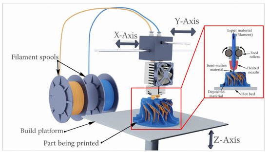
If you want high-quality 3D printed parts, then you need to choose the right print parameters. Research on this topic is ongoing, and the latest comes from the University of Manchester. Chamil Abeykoon, Pimpisut Sri-Amphorn, and Anura Fernando, with the Northwest Composite Centre in the Aerospace Research Institute, published “Optimization of fused deposition modeling parameters for improved PLA and ABS 3D printed structures,” about their work studying various properties and processing conditions of 3D printed specimens made with different materials.

There are multiple variables involved in 3D printing, and changing just one parameter could cause “consequential changes in several other parameters” at the same time. Additionally, the most commonly used FDM printing materials are thermoplastic polymers with low melting points – not ideal for “some high performance applications.”

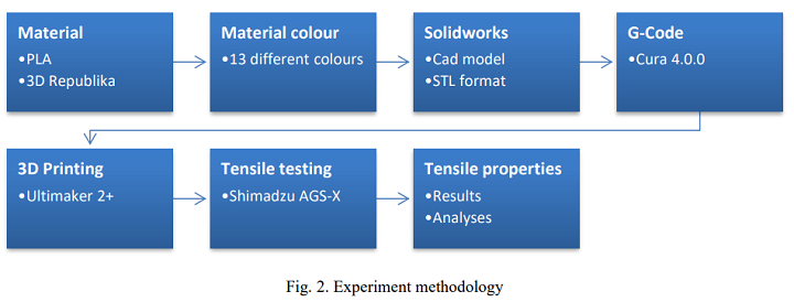
“Therefore, attempts have been made to improve the properties of printing filaments by adding particles such as short-fibres, nanoparticles and other suitable additives [18]. Thanks to these extensive researches and developments in the area of FDM, fibre-reinforced filaments are becoming popular and are currently available for practical applications,” they explained.

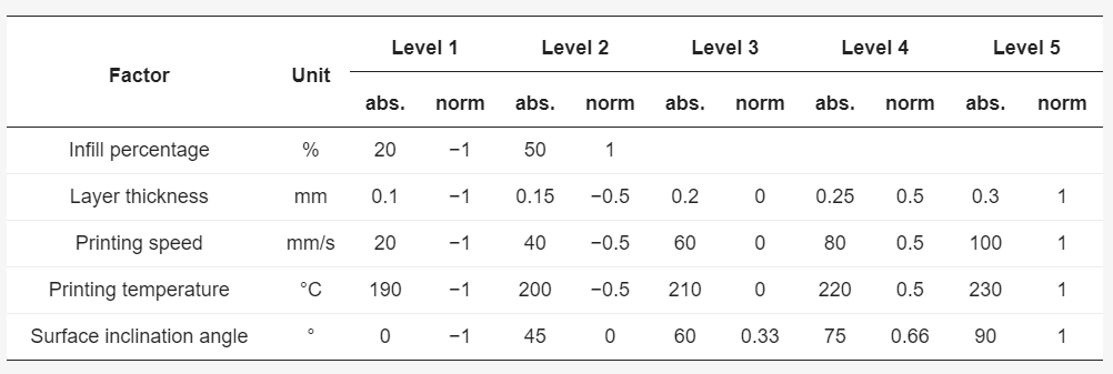
In order to optimize parameters and settings for these new reinforced materials, the team says we need more 3D printing research and development. In their study, they investigated the process using seven infill patterns, five print speeds, and four set nozzle temperatures, and observed and analyzed the mechanical, thermal, and morphological properties.

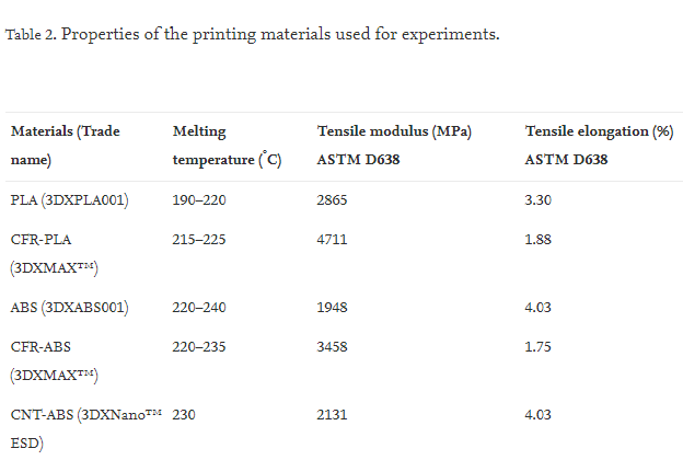
They used five commercially available materials, with 1.75 mm diameters:

  • Polylactic acid (PLA)
  • Acrylonitrile butadiene styrene (ABS)
  • Carbon fiber-reinforced PLA (CFR-PLA)
  • Carbon fiber-reinforced ABS (CFR-ABS)
  • Carbon nanotube-reinforced ABS (CNT-ABS)

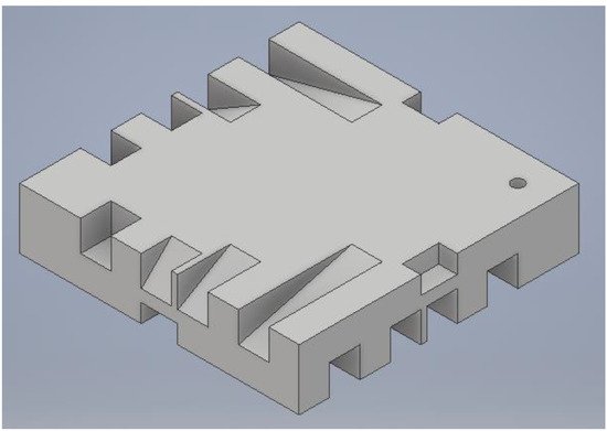
The samples were designed with SOLIDWORKS and printed on a MakerBot Replicator 2, MakerBot Replicator 2X, and MakerBot Replicator Z18.

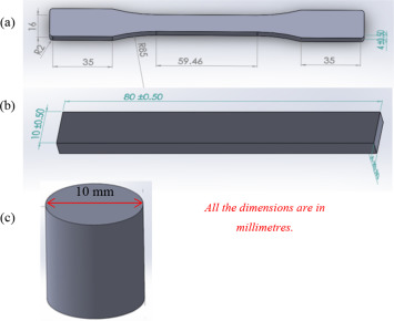
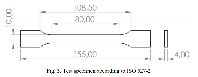
3D CAD images of test specimens: (a) Tensile, (b) Bending, and (c) Compression.

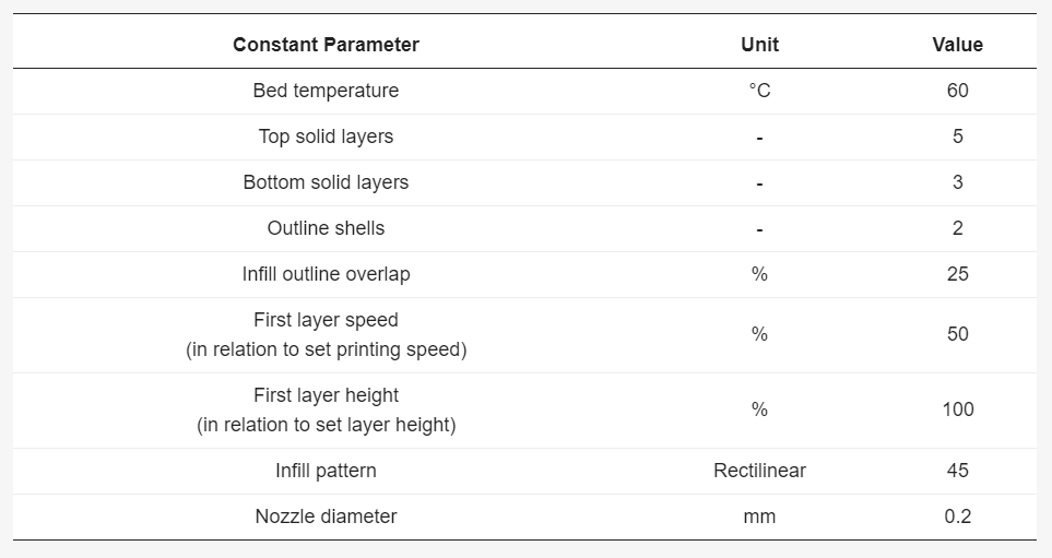
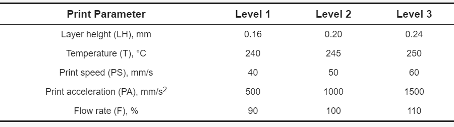
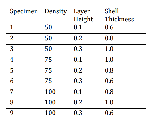
The team studied seven infill patterns – catfill, diamond, hexagonal, Hilbert, linear, moroccocanstar, and sharkfill –  and infill densities of 25%, 30%, 40%, 50%, 70%, 90%, and 100%. Two shell layers were used for all samples, and the print bed temperature was between 23-70° for CFR-PLA, and 110°C for the three types of ABS material, to help reduce shrinkage and warping.

“At each test condition of all the types of tests (mechanical, rheological and thermal), 3 test specimens were prepared and tested, and then the average value was taken for the data analysis to improve the accuracy and reliability of the experimental data,” the team wrote.

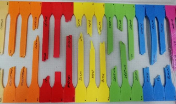
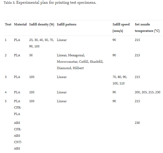
Appearance of the printed compression test specimens: (a) PLA, (b) ABS, (c) CFR-PLA, (d) CFR-ABS, and (e) CNT-ABS.

First, the 3D printed samples underwent mechanical testing to determine tensile modulus, flexural modulus, and compression properties. Using differential scanning calorimetry (DSC), the researchers measured melting and crystallization behaviors in a liquid nitrogen atmosphere, and found “the volume fractions of the reinforcement and matrix of the composite filaments” with the help of thermal gravimetric analysis (TGA).

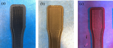
Appearance of printed tensile test specimens: (a) PLA, (b) ABS, (c) enlarged view of PLA, and (d) enlarged view of ABS.

Using a thermal imaging camera, they detected how much heat was released as the figure above was printed with 100% infill density, 20 mm/s infill speed, and 215°C set nozzle temperature. Finally, they used scanning electron microscopy (SEM) to observe and perform morphological testing on the surfaces of the 3D printed specimens that were broken during mechanical testing.

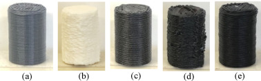
Infill density affects the strength of 3D printed parts. By increasing infill density, you then increase the tensile modulus and decrease porosity, which increases the “strength of the mechanical bonding between layers.”

Relationship between tensile modulus and infill density for PLA.

“For pure PLA, parts with 100% infill density obtained the highest Young’s modulus of 1538.05 MPa,” the researchers note.

But, structure gaps can occur more frequently with low infill densities, which reduces part strength. In the figure below, you can see “the changes in porosity of the structure with the infill density.”

3D printed specimens with infill densities: (a) 25% (b) 50% and (c) 100%.

“Of the tested infill speeds from 70 to 110 mm/s; 90 mm/s infill speed gave the highest Young’s modulus for pure PLA,” they wrote.

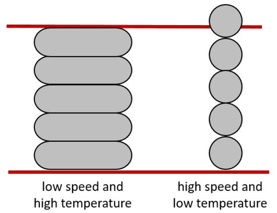
Print speeds over 90 mm/s could cause polymer filament to melt, and result in poor adhesion and lower strength. To avoid this, the print speed must be compatible with the set nozzle temperature, and an appropriate combination of speed and set nozzle temperature “can reduce the shrinkage of the parts being printed.”

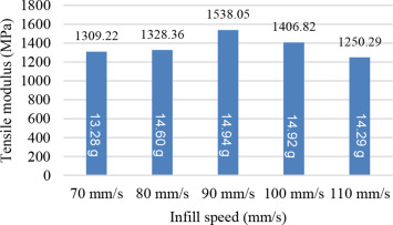
Relationship between tensile modulus and infill speed for PLA.

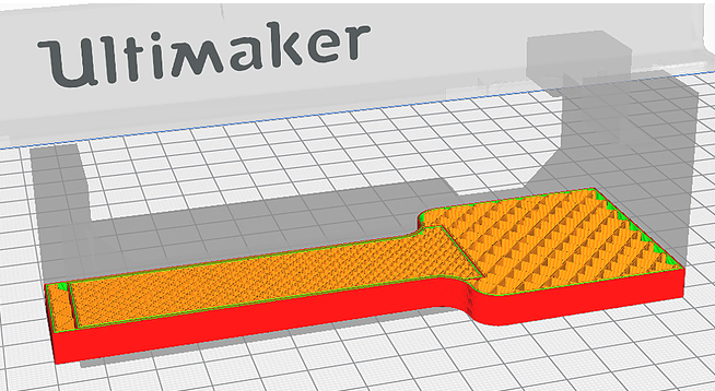
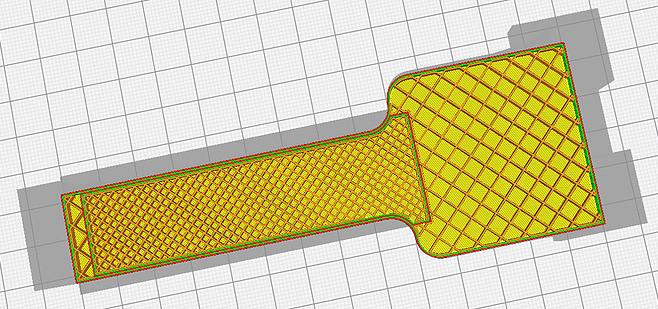
3D printed PLA samples were tested with the different infill patterns at 50% infill density, 90 mm/s speed, and 215°C set nozzle temperature.

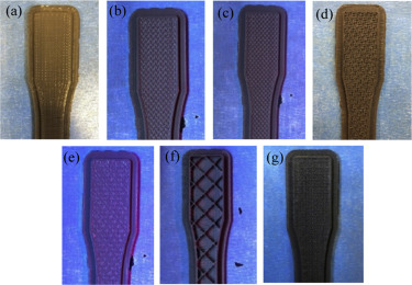
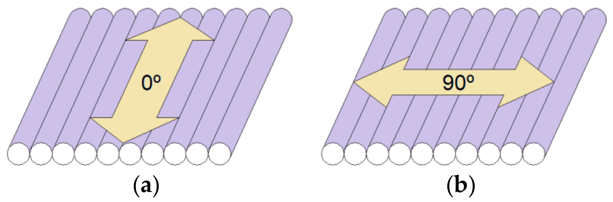
3D printed samples with infill patterns: (a) Linear, (b) Hexagonal, (c) Moroccanstar, (d) Catfill, (e) Sharkfill, (f) Diamond, and (g) Hilbert.

“Among these seven patterns, the linear pattern gave the highest tensile modulus of 990.5 MPa. This can be justified as the linear pattern should have the best layer arrangement (in terms of the bonding between the layers) with the lowest porous structure,” the team explained.

They found that the print temperature has “a significant effect on the tensile modulus.” 215°C provided the best tensile performance, as lower temperatures might cause poor melting, and thus weak bonding. The set nozzle temperature and print speed correlate, and “should be chosen carefully based on the material being used and the part geometry being printed.”

To study the effect on tensile properties, they were printed with the following parameters: 90 mm/s infill speed, linear pattern, 10% infill density, and 215°C set nozzle temperature for PLA, and 230°C for ABS. The researchers found that the tensile modulus of pure PLA (1538.05 MPa) was far higher than for pure ABS.

“In this study, CFR-PLA gave the largest tensile modulus of 2637.29 MPa while pure ABS (919.52 MPs) was the weakest in tensile strength,” they wrote.

Tensile modulus of the five printing materials.

Reinforcing ABS and PLA with fiber causes higher tensile modulus, though pure PLA was stronger than the CNT-ABS.

Even at 90° of bending, the PLA and ABS samples only had a small crack in the middle, and did not break.

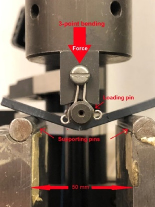
3D printed specimen in bending test.

At 1253.62 MPa, the CFR-PLA had the highest bending modulus, while pure PLA was the lowest at 550.16 MPa.

During compression tests, none of the materials were crushed or broken, and pure ABS was found to be the toughest.

“As evident, pure PLA gave the highest compressive strength while the compressive modulus of CFR-PLA (1290.24 MPa) is slightly higher than that of pure PLA (1260.71 MPa) (higher gradient of the liner region). CFR-ABS and CNT-ABS follow the same trend but CNT-ABS is slightly tougher than CFR-ABS,” the team explained. “Pure ABS shows the lowest compressive strength and modulus (478.2 MPa) but shows the most ductile behavior of the five materials.”

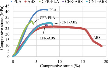
Compressive stress-strain curves of test materials.

Finite element analysis (FEA) by ANSYS was used to visualize stress distribution for the tensile, bending, and compression testing of PLA.

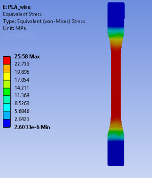
Equivalent stress distribution for tensile test.

“The stress distribution shows that a uniform stress is created in the gauge length of the test piece,” they explained.

“Higher compressive loading will cause the material to have internal crack initiations thereby allowing the PLA to buckle excessively.”

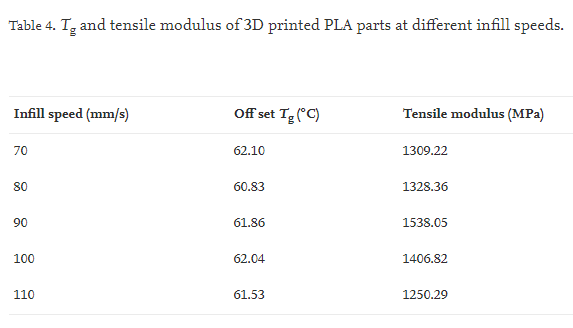
The team concluded through DSC analysis that “the strength of the 3D printed samples is dependent upon the set printing parameters and the printing materials more than the crystallisation.” While the infill speeds differ, the glass transition temperature (Tg) of the samples were similar.

“In this study, cooling of 3D printed parts occurred naturally by releasing heat to the surroundings while printing without any control on the cooling rate,” they stated.

DSC curves of PLA parts printed at different set nozzle temperatures.

As expected, the set nozzle temperature did not significantly effect the Tg, and material crystallization at different temperatures didn’t really affect part strength. But, the tensile modulus did change with the temperature.

TGA was used to analyze the weight loss variation of the composite materials against increased print temperature.

TGA diagrams of short fiber-reinforced composite filaments.

“Degradation temperatures (Td) of these materials can be determined from the mid-point of the descending part of each curve, which is approximately 331.85 °C for PLA. This value showed some sort of agreement to the value reported in commercial PLA data sheets – 353 °C,” they wrote.

Pure PLA typically has a higher Young’s modulus than pure ABS, so it can help to add “a higher volume fraction of reinforcement into the ABS matrix.” Brittle CFR-PLA and CFR-ABS filaments could have their flexibility affected if more carbon fiber is added, which can cause filament feed issues.

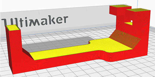
Thermal image during 3D printing.

An infrared thermal camera was used to observe 3D printing. The yellow area is the brightest, and hottest: this is where the polymer was extruded from the nozzle. The color changes to orange where the material starts to solidify, and the “red, pink, purple, and blue areas are at lower temperatures, respectively.” The red circle marks the temperature at the printer wall – less than the sample actually being printed.

“SEM images showed that the strength of the printed samples was dependent upon the arrangement of their layers,” the team noted.

Normal and SEM images of fracture surfaces of PLA samples: (a) 25% and (b) 100% infill density.

Observing the fracture surfaces of broken PLA samples with SEM showed that “the air gaps of 25% infill density sample is larger than that of 100% infill density.”

Looking at infill speed with SEM, the team noted that “the best orderliness” comes from 90 mm/s infill speed.

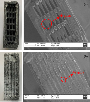
Incompatibility between the material matrix and the reinforcement can cause porosity in the 3D printed samples, but the latter can “contribute in increasing the mechanical properties by bearing the load.” You can see below that the pure PLA has a more regular layer alignment when compared to pure ABS.

SEM images of 3D printed parts at 19X magnification: (a) PLA, (b) ABS, (c) CFR-PLA, (d) CFR-ABS, and (e) CNT-ABS.

CFR-ABS is more porous than CFR-PLA, and both are rougher than the materials in their pure forms.

“Meantime, CNT-ABS shows a better arrangement of individual layers than the other two carbon fibre reinforced materials and also than the pure ABS as well,” they explained.

The last SEM images compare the size of the carbon fiber and carbon nanotube reinforcements. The fracture surface of the CNT-ABS shows some small holes, “due to the embedded carbon nanotubes in the matrix.”

“Compared to the matrix-reinforcement compatibility, both materials show some sort of incompatibility by having cracks and voids between the fibre and matrix,” they wrote.

“On the other hand, although the overall strength of CNT-ABS is improved by CNT particles, the flexibility of this material was decreased compared to the pure ABS as CNT-ABS being more brittle.”

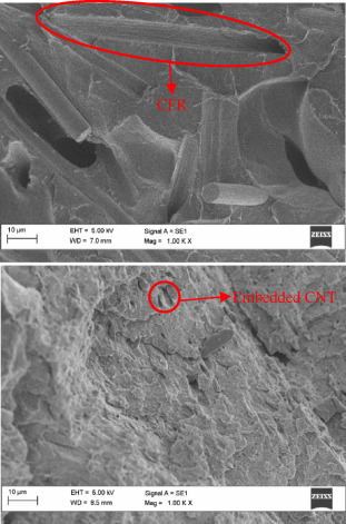
SEM images of fracture surfaces at 1.00 KX magnification: (a) CFR-PLA and (b) CNT-ABS.

They found that the optimal settings to improve the performance of the five 3D printing materials were 100% infill density, 90 mm/s infill speed, 215 °C of set nozzle temperature, and linear infill. Of the five materials, CFR-PLA had the strongest tension, bending, and compression, with the highest modulus.

Overall, it is obvious that the set printing parameters can significantly influence the mechanical properties of 3D printed parts. It can be claimed that the printing speed and set nozzle temperature should be matched to ensure proper melting of filaments and also to control the material solidification process,” the researchers concluded.

Discuss this and other 3D printing topics at 3DPrintBoard.com or share your thoughts below. 

The post Analyzing Parameters of Pure and Reinforced 3D Printed PLA and ABS Samples appeared first on 3DPrint.com | The Voice of 3D Printing / Additive Manufacturing.

Teton Simulation’s Software Automatically Finds and Tests Optimal 3D Printing Parameters

In order to achieve successful 3D prints, you need optimal print parameters. Enter slicing software, right? But, most slicers do not have a capability that would make things even easier – physical part simulation, in addition to a recommendation system for choosing those parameters.

US additive manufacturing software startup Teton Simulation, headquartered in Wyoming, is in the latter phases of R&D, and working towards production commercialization, for a really interesting technology called Intelligent Slicing. Teton was one of eight companies selected to present at last year’s RAPID + TCT Innovation Auditions, and is planning to officially announce its technology at this year’s AMUG Conference in March.

Doug Kenik

“The job of a slicer is simple: convert part geometry to instructions for 3d printers. Modern slicers do a great job of accomplishing this while providing the user with near complete control over how a part is printed,” Teton’s VP of Product Doug Kenik told 3DPrint.com. “However, while offering up these controls, slicers fail to provide any guidance into how these controls should be configured in order produce a part that must meet real-life performance requirements. This forces people into the tedious and time-consuming cycle of printing parts, testing them, then adjusting the print profile until they stumble upon a part that meets the requirements. At this point, they have a part that works, but have wasted countless days or weeks of productivity, machine time, and material.”

Physics-based Intelligent Slicing can be easily embedded into existing slicer programs. But, what exactly does Intelligent Slicing do?

“Our technology addresses the gap in the design cycle by guiding the user as to which print parameters to use in order to meet performance requirements while minimizing print time and material usage,” Kenik continued. “The first integration of our technology will be with Cura, which is a great starting point since they are one of the world’s most popular slicers for FFF parts. As a user, all you have to do is define end-use requirements, and then our optimizations routines churn in the background and deliver a list of optimized print profiles that the user can choose from. Since our technology runs in the cloud, we are able to run many parallels simulations which result in blazing fast solution times. At the end of the day, our objective is to save the user time by eliminating print iterations, increase productivity and machine throughput, and reduce material waste.”

According to the Teton website, its proprietary software technology can help users quickly achieve “automatic validation and optimization” of parameters so that parts meet the necessary manufacturing and performance requirements.

“We are currently commercializing technology that will optimize FFF/FDM part print parameters for manufacturing and performance requirements while minimizing print time, with the aim to reduce manufacturing cycles by an order of magnitude,” Rick Dalgarno, the Director of Alliances and Operations at Teton, told us. “Our technology is being integrated into commercial slicing products with the intent of embedding “intelligence” into slicers that is simple to use and fast.”

Rick Dalgarno

Dalgarno tells us that Intelligent Slicing automatically selects 3D printing parameters for optimal structural performance of parts.

A common way to determine the best print parameters is what Teton refers to in a blog post as the “build/break cycle.” If a 3D printed part breaks during testing, you can go back, change some of the parameters, and try it again until you finally have a part that doesn’t break, meaning you’ve landed on a valid set of parameters. Obviously, 3D printing does speed up this process, but it still takes time.

Slicing software is, according to Teton, “entirely disconnected from the initial design requirements,” and also requires a “staggering” amount of print parameters, which are unfortunately necessary as they are responsible for influencing how the part will actually perform in the real world. And while simulation software can help predict how a part will perform without the need for a physical model, a lot of these solutions require a decent amount of prior knowledge. Additionally, even if the software can portray a part’s internal structures, the accuracy of the model is not always perfect.

Teton’s Intelligent Slicing technology can not only optimize and validate print parameters, but also predict their impact on a 3D printed part’s performance. The software offers an intuitive, repeatable, and simple process to slice parts and help lower print iterations.

“Our intent is to remove the ambiguity and confusion of defining slicing parameters by automating the process and identifying the best potential paths the user can take to make a superior part, faster – a process we refer to as Intelligent Slicing,” the website states.

The company provides a good example of how to use its physics-based simulation tool with a bicycle pedal fixture that needs to be optimized for 3D printing.

The simulation tool is embedded in the slicer in order to optimize print parameters and validate the part’s structural performance.

“Let’s focus on infill density for the moment. Imagine that a part is required to have a factor of safety equal to 2. We can think of this as requiring the part to be twice as strong as it needs to be in operation,” the Teton blog states. “What infill density should we use to obtain the desired part strength?

“Suppose that we would like to see if an infill density of 20% would suffice. This value would result in relatively faster print times and lower material usage, but that’s useless if the part doesn’t perform.”

The Intelligent Slicing solution allows users to leverage simulation in the slicer itself to virtually test the part before ever pushing “Start Print Job.” If you receive negative results, no problem – just change the infill density until you find one that works.

Model of the pedal fixture in the Cura slicer

Teton software’s optimization capabilities are great, because Intelligent Slicing can easily tweak multiple possibilities, like layer height and width, the number of walls, and how many top or bottom layers a print might need. Just add the part’s requirements and with the simple press of a button, the software will “intelligently” search all the possibilities until it’s landed on valid parameters.

“Let’s consider this approach for the pedal fixture,” the blog continues. “After setting the requirement for a factor of safety to 2 and specifying how the part will be loaded and anchored, Teton’s software can be used to validate a user-defined set of print parameters or search for optimal choices for valid print parameters. As before, we focus on changing only the infill of the model, but this time, we give the task to the optimization software. In addition to tuning the infill density, our software will also test local variations in infill density using modifier meshes. Such spatially-varying infill properties can be used to great effect for structural performance, as they allow us to target inherently weaker areas of the part.”

Sliced, optimized part: The modifier mesh is in the middle, surrounded by its own walls, which contribute to part strength.

For increased strength, Intelligent Slicing also added a modifier mesh to the middle of the pedal. This helped achieve a set of parameters that resulted in “significantly less time and material usage” than changing up the global infill density would have.

The infill density inside the modifier mesh (45%) is noticeably higher than in the rest of the part (20%); a result of the localization of material to improve structural performance.

“Most of the structural simulation tools on the market are “analyst-level” tools, and we recognized that most people simply don’t have the education or training to feel comfortable in analyst-level workflows. In order to serve a broader market, we decided to develop a tool that could be used by anyone. This means that we had to figure out a way to automate all of the tasks that would typically require an analyst skill set,” Kenik told us about Teton’s target audience. “The end results is a highly automated workflow that is so easy to use, new users can be up and running in literally minutes. A lot of sophistication goes into making engineering software simple but we are very pleased with how we have been able to create an optimization tool that is highly accessible.”

I’ll be curious to hear the reviews of Intelligent Slicing, and see if Teton’s software is as good as it sounds.

Discuss this and other 3D printing topics at 3DPrintBoard.com or share your thoughts below.

[Images: Teton Simulation unless otherwise noted]

The post Teton Simulation’s Software Automatically Finds and Tests Optimal 3D Printing Parameters appeared first on 3DPrint.com | The Voice of 3D Printing / Additive Manufacturing.

How does PLA Color Influence Mechanical Properties in FDM 3D Printing?

All kinds of research has been conducted regarding the mechanical properties of 3D printing materials, such as how they are effected by things like infill density, build orientation, temperature, and porosity. Researchers Adi Pandžić and Damir Hodzic from the University of Sarajevo and Aleksa Milovanović with the University of Belgrade were curious how much the color of PLA would effect material tensile properties in FDM 3D printing, and published a paper on their work, titled “Influence of Material Colour on Mechanical Properties of PLA Material in FDM Technology.” Different colors need different extrusion temperatures in 3D printing. The additives that make your PLA a different color also have influence on how your part prints and what properties it has. This much was already known, but to which extent do the different color formulations influence your mechanical properties?

The abstract reads, “Topic of this article is to investigate whether colour of PLA material effect on material tensile properties and in what amount. It will be tested more than 10 different colours of PLA material, and for every colour it will be tested 3 specimens. Specimens are prepared according to ISO 527-2, and all printed with same 3D printing parameters and with 100% infill. Also, all used materials are of same company and for every colour specimen will be 3D printed from same filament spool. All this is done to avoid other parameters to effect on material properties. The results of this study will be useful for colour selection of the PLA material without compromising the material tensile properties of 3D printed product.”

Many parameters are taken into account when it comes to the quality of FDM printed products, including things like infill pattern, layer height, nozzle diameter, and material characteristics. Polylactic acid, or the popular PLA we all know and love, is a polymer with a melting point between 150°-160° C, and is still the reigning material on the desktop.

“By reviewing the literature it can be noticed that the greatest accent is given to the influence of parameters on mechanical properties of material. Another characteristic barely evaluated is the influence of different material pigmentations,” the researchers explained. “Today, there are many different colours of PLA material of the same manufacturer, and in most cases it is assumed to have the same mechanical properties regardless of colour. This is one of the reasons why we chose to examine whether and how much the colour of the PLA material influences the mechanical properties of the finished product.”

The team ordered 14 different colors of PLA from 3D Republika, with the same properties and characteristics, in order to investigate their potential influence on the mechanical properties of specimens made with the material. They used SOLIDWORKS to design samples according to ISO 527-2, and printed three different specimens for each color on an Ultimaker 2+, under the same conditions with 100% infill, and the “normal” profile from Cura 4.0.0 slicing software was used to prepare the G-code for the samples.

“Specimens are printed with “flat” printing orientation and 45˚ raster angle,” the researchers wrote. “Also brim around specimen is used for better adhesion with print bed and to reduce wrapping of material, after 3D printing it is removed from specimen.”

A Shimadzu AGS-X tensile machine was then used to perform tensile testing on the 42 3D printed PLA specimens. Properties like elastic modulus, strain, toughness, ultimate tensile strength (UTS), and yield strength were tested.

The team learned some interesting things, such as the fact that the red PLA had the highest elastic modulus, yield strength, and ultimate tensile strength, while pink had the lowest numbers for these. But, pink had the highest toughness and influence on strain, while blue had the lowest.

Once the testing was complete, the researchers determined the following:

• Color of PLA had an influence on elastic modulus, and varies up to 18% (from 2719MPa to 3217MPa) depending on color
• Color of PLA had an influence on yield strength, and varies up to 36% (from 30MPa to 41MPa) depending on color
• Color of PLA had an influence on ultimate tensile strength, and varies up to 31% (from 35MPa to 46MPa) depending on color
• Color of PLA had an influence on toughness, and varies over 300% (from 10J to 48J) depending on color
• Color of PLA had an influence on strain, and varies over 400% (from 7% to 108%) depending on color

“In future research, the influence of material colour on other mechanical properties (bending, hardness, pressure, etc.) should be examined, and also influence of colour on mechanical properties of other materials (ABS, PET, etc.),” they concluded.

Discuss this research and other 3D printing topics at 3DPrintBoard.com or share your thoughts in the Facebook comments below. 

The post How does PLA Color Influence Mechanical Properties in FDM 3D Printing? appeared first on 3DPrint.com | The Voice of 3D Printing / Additive Manufacturing.

Improving the Strength & Accuracy of 3D Printed Gears

In the recently published ‘Strength and geometry parameters accuracy improvement of 3D printed polymer gears,’ the authors focus on refining strength and precision in FDM 3D printing. Here, rotary motion is explored, as the Russian research team takes the opportunity to examine the improvement of polymer gears.

In line with the International Standard, according to 12 gears accuracy, ratings include kinematic accuracy, contact, and gear backlash fluency. The polymers featured exhibited the following:

  • Low elastic modulus
  • Significant linear expansion coefficient
  • Shrinkage at the stiffening
  • Parts dimensional instability

The researchers state that all these items show that polymer gears can meet the challenge of an 8…12 accuracy rating.

Workpiece drawing of a straight-toothed gear

Previous approaches have aimed at reducing material and overhangs in more complex geometries. Here the goal was to outline the gears coordinate system, define the shortest functional dimensional communications with basic elements, and ‘actualize’ FDM techniques, along with slicing software.

A gear works from the basic design datum and a sectional involute element. The basic element consists of the A4 base, the B1 base, and the C1 base.

Functional model for gears additive production; a) frontal projection; b) horizontal projection; c) main base set indicator; d) additional base set indicator; 1- uneven-numbered layer; 2- even-numbered layer; 3- building table; OрXр4Yр2Zрθ – 3D – printers coordinate system

While the basic three design datum set limits six degrees of freedom, the researchers state that at the same time neither of the six is doubled. Ultimately, six coordinates are enough in the case of the sectional involute element; however, the researchers state that it is unreasonable to set any coordinate relating Yθ coordinate axis having zero informativity, as it would lead to ‘both redundant over-positioning and location uncertainty.’

The researchers saw that additive techniques can be advantageous over conventional ones because of the datum sets, however, in considering the OX2YθZ4 basic coordinate system of the basic gear design datum, geometrical accuracy will increase with numerical coordinates values and ‘reduction of printing parts model points.

One of the disadvantages, however, is the contravention of the base and the inversion unanimity principle.

“To avoid over-positioning, it is recommended to equip the printer with the building as the functional locating tool, which is regulated by the two-angle. The work locating plane is positioned normal to the Zрθ printer axis, which is parallel to the nozzle movement. The table central hole axis can be used as the J2 auxiliary base whereby the XpO, YрO, ZрO zero-point coordinates of the OX2YθZ4 gear coordinate system are set at the 3D operation procedure,” concluded the researchers.

“Moreover, following the inversion principle the gear needs to move the same way as the one turning the А4 basic hole axis. It is impossible for 3D printers based on the conventional Cartesian coordinates system. The facts listed agree with conclusions presented regarding reasonability of 3D printer construction based on cylindrical coordinate systems.”

3D printing is attractive to engineers around the world, meaning that gears are often part of the equation for moving parts, from those made for toy race cars to spur gears, and even research studies centered around the strength of gears.

What do you think of this news? Let us know your thoughts; join the discussion of this and other 3D printing topics at 3DPrintBoard.com.

[Source / Images: ‘Strength and geometry parameters accuracy improvement of 3D printed polymer gears’]

The post Improving the Strength & Accuracy of 3D Printed Gears appeared first on 3DPrint.com | The Voice of 3D Printing / Additive Manufacturing.

University of Cordoba: Predicting Surface Roughness in FDM 3D Printing

Spanish researchers Juan Barrios and Pablo Romero experiment with different techniques in FDM 3D printing in the recently published, Decision Tree Methods for Predicting Surface Roughness in Fused Deposition Modeling Parts.’

Examining control parameters for achieving finishes, the researchers created PETG parts to compare models from three different tree algorithms—C4.5, random forest, and random tree. Working with 27 different models, the team examined:

  • Layer height
  • Extrusion temperature
  • Print speed
  • Print acceleration
  • Flow rate

In addition, a dataset has been created to evaluate the models, consisting of 15 additional instances. The models generated by the random tree algorithm achieve the best results for predicting the surface roughness in FDM parts. Data mining can be used to improve 3D printed products based on prior information, demonstrating which methods and parameters are most effective in surface finishing as well as other manufacturing methods like tooling and machining.

Data mining is either supervised and consists of classification and regression, or is unsupervised, consisting of clustering, association rules, and correlations.

“To use these techniques, different classes must be established in which each instance in the database must belong to a class; the rest of the attributes of the instance are used to predict that class. The objective of these algorithms is to maximize the accuracy ratio of the classification of new instances,” stated the researchers.

Decision trees are extremely useful for classifying data, with tree nodes acting as conditions for attributes—with each leaf representing the instances belonging to a class. Researchers rely on these algorithms for engineering predictive models.

The 27 samples were designed in SolidWorks and then 3D printed on an Ender 3 using PETG filament, each with a dimension of 25.0 mm × 25.0 mm × 2.4 mm.

Factors and levels used in the design of the experiments (DOE).

Surface roughness was measured using a Mitutoyo perthometer model SJ-201.

Measurement of surface roughness in the direction parallel to the direction of extrusion (a) and in the direction perpendicular to the direction of extrusion (b).

The J48 algorithm was relied on in this research to plot trees that are not only comprehensive, but according to the research team are also ‘easily understood’ as well as predicting parameters for roughness, to include PA, LH, and F for Ra,0; F, PS, and LH for Ra,90.

“PA is the parameter with the greatest influence on Ra,0; F, PS, and LH are the parameters with the greatest influence on Ra,90. However, in this case, the models created with J48 algorithm were not able to predict the data used in the test. This may be related to overfitting problems,” concluded the researchers. “In the problem addressed, the random forest algorithm obtained better results than J48, as could be expected from the literature.”

“In future works, we intend to study whether the decision trees can be used to generate models that allow for the prediction of a better dimensional accuracy of the parts manufactured by FDM. The impact of other print factors on the surface properties of printed parts, such as nozzle diameter, will also be studied.”

Detailed precision parameters achieved by each algorithm for the Ra,90 prediction model.


Time used by each algorithm to build and validate the model.

Study of topologies and issues like surface roughness and finishing continue to be critical to 3D printing enterprises as users explore issues with complex internal structures, antibacterial surfaces, hydrophobic and hydrophilic surfaces, and more.

What do you think of this news? Let us know your thoughts! Join the discussion of this and other 3D printing topics at 3DPrintBoard.com.

The post University of Cordoba: Predicting Surface Roughness in FDM 3D Printing appeared first on 3DPrint.com | The Voice of 3D Printing / Additive Manufacturing.

Russian Lab Optimizes FDM 3D Printing Processes Leading to Increased Part Strength of 108%

In this study, Russian researchers sought to optimize FFF 3D printing parameters further, improving on strength and optimization processes. Their findings were released in the recently published ‘Desktop Fabrication of Strong Poly (Lactic Acid) Parts: FFF Process Parameters Tuning,’ as the team created five different samples from CAD models of parts, 3D printed on an Ultimaker 2. Their initial goal was to increase mechanical properties, allow for predictable quality, and stronger parts overall.

Testing part geometry optimization and results of study

Shape 1 was used to represent FFF 3D printed parts as the geometry suddenly forms a weak spot—with the rest of the samples working as designs to fix the issue in Shape 1:

  • Shape 2 was created to increase the strength of weak areas with a new material.
  • Shapes 2&3 were meant to increase part strength with FFF 3D printing in mind.
  • Shape 4 is the result of numerous design iterations.
  • Shape 5 mixes traditional approaches and FFF 3D printing optimization practices.

“Current work shows the effect of tuning the FFF process parameters on the strength of the samples of the same five shapes. Along with ‘coarse’ tuning — altering printing parameters for the whole printing cycle, the “fine” tuning is also studied,” stated the researchers. “In the latter case three parameters are varied during the printing cycle depending on the specific part of the sample being printed. It is shown that for a complex part, only for an optimized geometry (and only for it) significant increment of mechanical performance is achievable by optimization of FFF process parameters.”

For Shape 1, the results were vastly different. Interlayer bonding strength was ‘completely inefficient. Shapes 2-5, there was a significant increase in the part strength.

“It is clearly visible that the air corridors at the boundaries between plastic threads are fragmented and coalesce on the fracture of the Shape 5 sample, printed in mode D,” stated the researchers.

Shape 1 dimensions (a) and constitution (b) with shell interruption highlighted

The following parameters remained the same in each case:

  • Nozzle diameter (0.6 mm)
  • Heated bed temperature (60 °С
  • The first layer thickness (0.3 mm)
  • The first layer printing speed (25 mm/s).

“The effectiveness of coarse (modes B, C, D) and fine (mode E) FFF tuning for all tested shapes can be evaluated from the Figure 15. Parts of Shape 1, contained critical shell interruption, cannot be strengthened by technological mode optimization as it is shown on the chart (red bars). For all other tested shapes modifying technological modes led to a significant positive effect. Significant increase in strength without loss of product surface and dimensional quality can be achieved by reducing the layer thickness (Shapes 2, 3, 4 and 5, mode C) or by fine tuning the 3D printing parameters (Shape 5, mode E),” concluded the authors.

As 3D printing continues to progress, with multiple offshoots branching off into their own impressive realms from bioprinting to 4D printing, researchers continue to tighten up processes in FFF 3D printing from working with defects to improving speed exponentially. What do you think of this news? Let us know your thoughts! Join the discussion of this and other 3D printing topics at 3DPrintBoard.com.

Destruction of Shape 3 samples printed in mode A [61] (a) and mode B (b). For the mode B sample,
after the test is over, it is still not possible to separate the shaft from the boss with bare hands

[Source / Images: ‘Desktop Fabrication of Strong Poly (Lactic Acid) Parts: FFF Process Parameters Tuning’]


The post Russian Lab Optimizes FDM 3D Printing Processes Leading to Increased Part Strength of 108% appeared first on 3DPrint.com | The Voice of 3D Printing / Additive Manufacturing.

Researchers Strive to Improve 3D Printing Parameters for Foodies

The potential for 3D printed food and associated hardware, software, and materials is vast—causing researchers from China and Australia to look further into the merits of the technology and more specific features like slicing methods during the 3D design process. Authors Chaofan Guo, Min Zhang, and Bhesh Bhandari outline their work in the recently published paper, ‘Model Building and Slicing in Food 3D Printing Processes: A Review.’

While much attention has been paid to the methodology of fabricating foods via 3D printers, the intricacies of design and settings are rarely discussed. The authors strive to focus on 3D printer requirements, settings for slicing, and techniques and optimization processes.

As the necessary hardware has become available and improved over time, it has been proven that 3D printed foods can be produced—as well as ‘trimmed, cooked, or baked as required.’ The authors point out, however, that challenges still arise regarding structure and stability, performance of ingredients, post-processing methods, and resulting issues with deformation of prints.

The following printing parameters are crucial:

  • Printing height
  • Printing rate
  • Nozzle diameter
  • Nozzle movement rate
  • Layer thickness
  • Temperature

The whole process starts with a design, and not only should that be one that is functional and stable—it should please consumers and meet their varying needs. The authors point out that while CAD-based model building is extremely useful for those with extensive experience, most users and designers benefit in working with a template or a scanned object. Pre-established models have been very helpful in previous research too, such as the fabrication of lemon juice gel printed objects.

The military has embraced 3D printing for many different uses, and food is one of them as sustenance can be customized, made in smaller and more lightweight form, and stored easily. The designs, however, must be well-structured, and contain a high percentage of infill.

“Moreover, combining with the ultrasonic agglomeration, the particles of 3D printed objects can be fused together by emitting ultrasonic waves,” state the researchers.

Pictures of lemon juice gel printed objects. (A)–(D) are cylinders with different nozzle diameter (A = 0.5 mm, B = 1.0 mm, C = 1.5 mm, D = 2.0 mm). (E)–(I) are products printed at 24 mm3/s extruded rate, 30 mm/s nozzle moving speed and 1.0 mm nozzle diameter (E. Anchor, F. Gecko, C. Snowflake, D. Ring, E. Tetrahedron) (Yang et al. 2018).

NASA has continued to experiment with 3D printing in the food arena as well, but with challenge:

“Current food systems cannot meet the shelf‐life and nutritional needs of long‐term missions,” state the researchers. “The ‘printing’ machine in spacecraft based on additive manufacturing can print various food geometries from food ingredients for astronauts to ‘reconstituted’ foods. These ‘reconstituted’ foods can be made by designed shapes or scanned models from regular foods, which will be helpful to reduce the boredom of long‐term space operations.”

Ongoing research into better 3D printing of food for long-term missions for astronauts has resulted in the development of complex structures, however, with designs created to mimic skeleton and cardiac muscle—printed with protein-rich inks. 3D printing technology has also proven to be helpful in education as kids enjoy making food while mastering different aspects of STEM learning.

And while many of us have the best of intentions when baking a cake or making a gourmet delicacy, we don’t always have the mastery—or talent—to pull off complex endeavors with food. With 3D printing, users (as well as restaurateurs) can create customized, complex shapes but leave the precision to the printer:

“Although, theoretically, 3D food printing technology has come out for some time, until 2016 the world’s first 3D food printing restaurant was set up by Food Inc. at London. In September 2018, Jan Smink, Top Chef and Ambassador of byFlow, opened his new restaurant in Walwiga, bringing 3D print cuisine into our sight. Cuisines made by 3D printing technology can create a special experience for the guests with an artistic appearance made by fully designed models,” state the researchers.

Photos of 3D printed dishes made by Jan Smink. (A) Celery Hazelnut Paste, (B) Berenhap 2.0 with curry paste, and (C) 3D printer cream cheese.

Slicing software is critical for numerous reasons—but mainly in converting .stl files to G-Code. Beginners may be working with slicing software that is pre-set, while more advanced users are able to set all the parameters, and in some cases even assisting in repair.

“Besides the model design, 3D printer and printing materials optimization, slicing software is another crucial factor that can achieve an optimized printing effect. The slicing software is an intermediate driver for route planning and calculating sections between the 3D model and the 3D printer. In other words, slicing software is a tool that can transform the digital model into a hypostatic model,” state the researchers.

A brief summary of 3D models in some specific food printing areas

Overall, while the researchers note the tremendous amount of innovation and progress developers have made over the years, they recommend that more attention be given to developing models for 3D printing food—especially in model building and slicing software. This should begin with further study of consumers who would enjoy the technology, along with developing specific slicing technology for 3D printing food and making more extensive use of numerical analysis.

While 3D printing offers a wide range of industrial uses that have the potential to change the way we manufacture objects, prototypes, and parts forever, there are many fun aspects to the technology as well—and everyone loves to check out what’s happening on the food front, especially if it is around mealtime! Over the years, engineers and designers have brought us different ways to extrude food, from 3D printed steak or chicken to fancy pancakes and even concepts for airline food or meals to be fabricated in nursing homes for patients with dysphagia (trouble swallowing).

What do you think of this news? Let us know your thoughts! Join the discussion of this and other 3D printing topics at 3DPrintBoard.com.

Samples printed by using the 2‐nozzle 3D printer. Method A: create two pre‐designed separate 3D standard triangle language (stl) models sharing the same coordinates within Rhinoceros program. The two stl files were then merged into a single multi‐material file and assigned each file to one extruder (one material). Method B: create one 3D stl model and divide it into “infill part” and “perimeters part”, and each part was then assigned to one extruder (one material). The photos in Method B were taken at the beginning, middle and finishing stage during printing process from left to right (Liu et al., 2018c).

[Source / Images: ‘Model Building and Slicing in Food 3D Printing Processes: A Review’]

India: Improving FDM 3D Printing Through Process Parameter Optimization

In ‘Process Parameter Optimization for FDM 3D Printer,’ researchers from India discuss varying ways to improve popular fabrication processes, exploring basic parameter settings like density, layer height, and shell thickness—and how they affect mechanical properties like surface roughness, hardness, and tensile strength of 3D printed parts.

Specimen printing parameter variations

Using 1.75mm PLA as their material of choice, the scientists used an I3D Minds 3D printer for testing, SOLIDWORKS for design, and CURA for slicing. The I3D Minds offers a build volume of 190x190x180 mm and nozzle diameter of 0.4 mm, and automated setup and manufacturing.

Design samples were opened in CURA, and varying parameters were set:

  • Different layer heights – 0.1mm, 02mm, and 0.3mm
  • Fill densities – 50%, 75%, 100%
  • Shell thickness – 0.6mm, 0.8mm, 1.0mm

Sample files were converted into G-Code, and then sent to the 3D printer:

“The nozzle was maintained a temperature of 215 ºC for the extrusion of the PLA material and the build plate was maintained at 60 ºC,” stated the authors. “The printer prints the layer through the nozzle print head onto bed, one layer by layer, from bottom to top, and the same test setup was used for all specimens. The post hardening was observed to investigate the unconditional effect of printing parameters on physical and mechanical properties of the printed specimens.”

Cad modeling

The researchers also touched on common issues such as how to prevent issues due to common errors that may occur at the .stl file stage, often easily averted with ‘repair’ fixes in the original model.

“Generally, STLs that have been produced from a model obtained through 3D scanning often have more of these errors,” said the authors. “This is due to how 3D scanning works—as it is often by point to point acquisition, reconstruction will include errors in most cases.”

Printing a ‘slightly oversized version’ of the object is also suggested for greater precision in parts.

In discussing the Taguchi method, created by Dr. Genichi Taguchi, one of the leaders in parameter design, the researchers suggest using an orthogonal array for balanced results. This balance also means that each part can be evaluated on its own because each one is equal.

“On the basis of varying different parameters in different levels a Design of Experiments was carried out which can be used for preparation of specimens for optimization of 3D printed products for different parameters of 3D printing,” concluded the researchers. “Testing machines are selected for testing mechanical properties such as tensile strength, hardness and surface roughness of 3D printed specimens.”

While many may refer to 3D printing as magical, plenty of brainpower—in labs around the world—still goes into thinking of ways to refine nearly all methods. In FDM printing, researchers explore ways to improve layer adhesion, review how products like sensors are created, and discuss popular types of composites. Find out more about how scientists are improving parameter optimization here. What do you think of this news? Let us know your thoughts! Join the discussion of this and other 3D printing topics at 3DPrintBoard.com.

Surface roughness test

[Source / Images: Process Parameter Optimization for FDM 3D Printer]

3D Printing News Briefs: January 19, 2019

Welcome to the first edition of 3D Printing News Briefs in 2019! We took a brief hiatus at the beginning of the new year, and now we’re back, bringing you the latest business, medical, and metal 3D printing news. First up, Sigma Labs has been awarded a new Test and Evaluation Program Contract, and Laser Lines is now a certified UK Stratasys training provider. Michigan’s Grand Valley State University, and a few of its partners, will be using Carbon 3D printing to make production-grade parts for medical devices. Cooksongold is launching new precious metal parameters for the EOS M 100 3D printer, and VBN Components has introduced a new metal 3D printing material.

Sigma Labs Receives Test and Evaluation Program Contract

This week, Sigma Labs, which develops and provides quality assurance software under the PrintRite3D brand, announced that it had been awarded a Test and Evaluation Program contract with a top additive manufacturing materials and service provider. This will be the company’s fifth customer to conduct testing and evaluations of its technology since September 2018, and Sigma Labs will install several PrintRite3D INSPECT 4.0 in-process quality assurance systems in the customer’s US and German facilities under the program. It will also support its customer in the program by providing engineering, hardware, metallurgical consulting and support services, software, and training.

“Sigma Labs is deeply committed to our In-Process Quality Assurance tools, supporting and moving forward with them,” said John Rice, the CEO of Sigma Labs. “I am confident that this initiative, which marks our fifth customer signed from diverse industries in the past four months, will validate our PrintRite3D technology in commercial-industrial serial manufacturing settings. We believe that going forward, AM technology will play an increasingly prominent role in the aerospace, medical, power generation/energy, automotive and tooling/general industries, all areas which are served by this customer.”

Laser Lines Announces New Stratasys Training Courses

Through its new 3D Printing Academy, UK-based total 3D printing solutions provider Laser Lines is now a certified provider of Stratasys training courses. The custom courses at the Academy for FDM and Polyjet systems are well-suited for new users, people in need of a refresher, or more experienced users, and include tips and tricks that the company’s certified trainers have personally developed. One-day and two-day courses are available at customer sites, or at the Laser Lines facility in Oxfordshire.

“The training courses are an extension of the advice and education we have been providing to customers for the past 20 years. With our experienced team able to share their knowledge and experience on both the FDM and Polyjet systems and materials, customers who are trained by us will get the value of some real life application examples,” said Richard Hoy, Business Development at Laser Lines.

“We want to ensure that our customers get what they need from our training so before booking, our Stratasys academy certified trainers can discuss exact requirements and advise both content and a suitable duration for the training course so that it meets their needs entirely.”

Exploring Applications in Medical Device Manufacturing

Enabled by Michigan state legislation, the Grand Rapids SmartZone Local Development Finance Authority has awarded a half-million-dollar grant that will be used to fund a 2.5-year collaborative program centered around cost and time barriers for medical devices entering the market. Together, Grand Valley State University and its study partners – certified contract manufacturer MediSurge and the university’s applied Medical Device Institute (aMDI) – will be using 3D printing from Carbon to create production-grade parts, out of medical-grade materials and tolerances, in an effort to accelerate medical device development, along with the component manufacturing cycle. A Carbon 3D printer has been installed in aMDI’s incubator space, where the team and over a dozen students and faculty from the university’s Seymour and Esther Padnos College of Engineering and Computing will work to determine the “tipping point” where 3D printing can become the top method, in terms of part number and complexity, to help lower startup costs and time to market, which could majorly disrupt existing manufacturing practices for medical devices.

“We are thrilled to be the first university in the Midwest to provide students with direct access to this type of innovative technology on campus. This novel 3D additive manufacturing technology, targeting medical grade materials, will soon be the new standard, and this study will be a launch pad for course content that is used in curriculum throughout the university,” said Brent M. Nowak, PhD, the Executive Director of aMDI.

New Precious Metal 3D Printing Parameters at Cooksongold

At this week’s Vicenzaoro jewelry show, Cooksongold, a precious metal expert and the UK’s largest one-stop shop for jewelry and watch makers, announced that it is continuing its partnership with EOS for industrial 3D printing, and will be launching new precious metal parameters for the EOS M 100 3D printer, which is replacing the system that was formerly called the PRECIOUS M 080. The EOS M 100 builds on the powder management process and qualities of the PRECIOUS M 080, and the new parameters make it possible for users to create beautiful designs, with cost-effective production, that are optimized for use on the new 3D printer.

“We are proud to continue our successful partnership with Cooksongold, which was already established 2012,” said Markus Brotsack, Partner Manager at EOS. “The EOS M 100 system increases productivity and ensure high-quality end parts as we know them. Based on our technology, EOS together with Cooksongold plans to develop processes for industrial precious metals applications too.”

VBN Components Introducing New Cemented Carbide

Drill bits in Vibenite 480; collaboration with Epiroc.

In 2017, Swedish company VBN Components introduced the world’s hardest steel, capable of 3D printing, in its Vibenite family. Now it’s launching a new 3D printing material: the patented hard metal Vibenite 480, which is a new type of cemented carbide. The alloy, which has a carbide content of ~65%, is heat, wear, and corrosion resistant, and based on metal powder produced through large scale industrial gas atomization, which lowers both the cost and environmental impact. What’s more, VBN Components believes that it is the only company in the world that is able to 3D print cemented carbides without using binder jetting. Because this new group of materials is a combination of the heat resistance of cemented carbides and the toughness of powder metallurgy high speed steels (PM-HSS), it’s been dubbed hybrid carbides.

“We have learned an enormous amount on how to 3D-print alloys with high carbide content and we see that there’s so much more to do within this area,” said Martin Nilsson, the CEO of VBN Components. “We have opened a new window of opportunity where a number of new materials can be invented.”

Early adopters who want to be among the first to try this new material will be invited by VBN Components to a web conference at a later date. If you’re interested in participating, email info@vbncomponents.com.

Discuss these stories and other 3D printing topics at 3DPrintBoard.com or share your thoughts in the Facebook comments below.