Michigan Tech Develops Open Source Smart Vision for 3D Printing Quality Control

Monitoring and quality control systems are becoming more widespread in additive manufacturing as a means of ensuring repeatability and aiming for first-time-right parts. A greater need for quality control are now trickling down to items that are more commonly made by the average consumer using FFF 3D printers, as detailed in “Open Source Computer Vision-based Layer-wise 3D Printing Analysis,” by Aliaksei L. Petsiuk and Joshua M. Pearce.

Dr. Joshua Pearce, an associate professor of materials science & engineering, and electrical & computer engineering at Michigan Technical University has performed extensive research into 3D printing, recyclability, and open-source platforms, along with protocrystallinity, photovoltaic technology, nanotechnology, and more.

As a proponent of 3D printing household items rather than purchasing them, Pearce foresees that the technology will infiltrate the mainstream and the average household much more deeply in the future. While there are many skeptics, this thinking is in line with many other tech visionaries who see great potential for 3D printing on all levels.

In a press release sent to 3DPrint.com, Pearce explains that quality control continues to be an issue at the household level—leading him to create a visual servoing platform for analysis in multi-stage image segmentation, preventing failure during AM, and tracking of errors both inside and out. In referring to previous research and development of quality control methods for “more mature areas of AM,” the authors realized that generally there is no “on-the-fly algorithm for compensating, correcting or eliminating manufacturing failures.

Analysis in Pearce’s program begins with side-view height validation, measuring both the external and internal structure. The approach is centered around repair-based actions, allowing users to enjoy all the benefits of 3D printing (speed, affordability, the ability to create and manufacture without a middleman, and more) without the headaches of wasted time and materials due to errors that could have been caught ahead of time. The overall goal is to “increase resiliency and quality” in FFF 3D printing.

3D printing parameters allowing failure correction

“The developed framework analyzes both global (deformation of overall dimensions) and local (deformation of filling) deviations of print modes, it restores the level of scale and displacement of the deformed layer and introduces a potential opportunity of repairing internal defects in printed layers,” explain Petsiuk and Pearce in their paper.

Parameters such as the following can be controlled:

  • Temperature
  • Feed rate
  • Extruder speed
  • Height of layers
  • Line thickness

While in most cases it may be impossible to compensate for mechanical or design errors, a suitable algorithm can cut down on the number of print failures significantly. In this study, the authors used a Michigan Tech Open Sustainability Technology (MOST) Delta RepRap FFF-based 3D printer for testing on a fixed surface improving synchronization between the printer and camera, based on a 1/2.9 inch Sony IMX322 CMOS Image Sensor and capturing 1280×720 pixel frames at a frequency of 30 Hz.

Visual Servoing Platform: working area (left), printer assembly (right): a – camera; b – 3-D printer frame; c – visual marker plate on top of the printing bed; d – extruder; e – movable lighting frame; f – printed part.

Projective transformation of the G-Code and STL model applied to the source image frame: a – camera position relative to the STL model; b– G-Code trajectories projected on the source image frame. This and the following slides illustrate the printing analysis for a low polygonal fox model [63].

The algorithm monitors for printing errors with the one camera situated at an angle, watching layers being printed—along with viewing the model from the side:

“Thus, one source frame can be divided into a virtual top view from above and a pseudo-view from the side.”

3D printing control algorithm

Currently, the study serves as a tool for optimizing efficiency in production via savings of time and material but should not be considered as a “full failure correction algorithm.”

Example of failure correction

Interested in finding out more about how to use this open-source analysis program? Click here.

[Source / Images: “Open Source Computer Vision-based Layer-wise 3D Printing Analysis”]

The post Michigan Tech Develops Open Source Smart Vision for 3D Printing Quality Control appeared first on 3DPrint.com | The Voice of 3D Printing / Additive Manufacturing.

Optical Metrology: The key to quality control in additive manufacturing

While 3D printing has been around for quite some time, it has only recently come of age as manufacturers are realizing that the technology can be used for more than just prototyping. In fact, today’s forward-thinking manufacturers are implementing 3D printing to accelerate their entire product development processes.

Designers and manufacturers now overcome fabrication limitations with 3D printing

Nowadays, 3D printing technologies can quickly produce functional and highly complex objects from hundreds of different types of materials—with none of the cutting, bending and injection limitations of traditional fabrication methods. Moreover, 3D printing applied to manufacturing can reduce total investment in machines, tools, assembly, and materials.

However, while additive manufacturing has definitely changed the way products are made and offers unprecedented versatility, inspection, and quality control issues nevertheless remain. How can quality control teams verify if objects with complex shapes are made according to original design intent, technical specifications and required norms? And while new 3D printers are designed specifically for additive manufacturing to ensure quality repeatability for long production runs, what are the solutions to mitigate defects and material waste?

This is where 3D scanners come into play. 3D scanners are a non-contact means to quickly characterize object surfaces so as to test and control part quality. Non-destructive testing using coherent light can find minuscule defects, discover when materials deviate from standard, measure and report on surface issues, and more. Unlike more manual methods, including coordinate-measuring machines, portable 3D scanners often don’t require hard setup and the part doesn’t have to go to a metrology lab.

Portable 3D scanners can find minuscule defects without requiring hard setup

The latest models gather millions of measurements in seconds, supplying the results automatically into interpretive software. The Creaform HandySCAN BLACK™|Elite, for example, features high-end cameras, blue laser technology and advanced algorithms for fast metrology-grade measurements. It is a handheld scanner, usable in any environment and on any surface. It captures 1.3 million points per second, automatically generating a 3D mesh twin of the scanned object.

High-resolution, handheld 3D scanning brings inspection to the production line. These new optical solutions introduce innovative concepts like self-positioning and dynamic referencing, which enables the measuring device to be continuously locked to the part by an optical link. Specialized accompanying software turns these millions of points into coherent 3D mesh models, easily incorporated into other software tools as required.

Combined, 3D scanning and 3D printing optimize the whole manufacturing process.

Taking 3D scanning to 3D printing makes it possible to more rapidly test for quality. Research shows QC issues will vary according to the 3D printing process in use, the amount of copies made in one production run, and more. Warping is a problem, for example, in thermoplastic products with elongated horizontal rectangular shapes but not as much for vertical shapes. Such warping is usually not found in the first part printed, but happens when the printer is used for long periods. Such issues are not simple to predict; the potential for deviation from the norm is a four-part problem of 3D printer make and model; the material in use; the specific 3D print method; and the length of the production run.

Time compression is one important reason manufacturers turn to Additive Manufacturing, so it is important the time gained using high-resolution 3D scanning isn’t lost during the subsequent inspection phase. To streamline the QC process Creaform offers its VXinspect™ software as part of 3D scanning suite. It automates the process of setting up and running a full geometric dimensioning and tolerance (GD&T) inspection. The mesh created with their 3D scanners can be compared directly against the CAD data used to create the 3D printed object.

Streamline the whole inspection process with a complete and integrated solution

The HandySCAN BLACK is ready for use in creating new quality control processes for additive manufacturing. Scanned data converted to a 3D mesh in VXinspect can be exported to a variety of leading engineering and modeling software products including various 3D Systems Geomagic solutions; InnovMetric Software PolyWorks; Dassault CATIA V5 and SOLIDWORKS; PTC Creo; Siemens NX and Solid Edge; and Autodesk Inventor, Alias, 3ds Max, and Maya. The scanner is set to calculate positioning based on reflective targets to guarantee accuracy regardless of the environment. Part size can be anywhere from 0.05 meters to 4 meters with a measurement resolution of 0.05 mm.

All traditional manufacturing processes now include built-in quality control; there are yet no commonly accepted processes for QC in additive manufacturing. The leading national and international standards agencies are working on a common set of guidelines, but the final details suitable for all additive manufacturing processes are years away. For now, digital inspection using 3D scanning allows progressive manufacturers to create internal, repeatable, and accurate inspection workflows for their additive manufacturing projects. The body of data gathered with 3D scanning will be essential in the creation of artificial intelligence deep learning algorithms, required to take quality control in additive manufacturing to the next level.

The post Optical Metrology: The key to quality control in additive manufacturing appeared first on 3DPrint.com | The Voice of 3D Printing / Additive Manufacturing.

3D Printing News Briefs: May 1, 2019

In today’s 3D Printing News Briefs, we’ve got stories on events and business for you, followed by an innovative piece of 3D printed furniture. The fourth Metal Additive Manufacturing Conference will be held in Sweden this November, and Oerlikon AM will soon be hosting the grand opening event for its new Innovation Hub. Link3D is partnering up with Additive Rocket Corporation, and an industrial designer created a 3D printed chair that can fold up flat.

MAMC 2019 Coming to Sweden this November

From November 25-27, 2019, the fourth Metal Additive Manufacturing Conference (MAMC 2019) will take place in Örebro, Sweden. In addition to keynotes and other presentations, there will also be site visits to metal additive manufacturing companies and users AMEXCI, Lasertech LSH, and Siemens Industrial Turbomachinery. Then, directly following the conference, the Austrian Society for Metallurgy and Materials (ASMET) will be holding a two-day metal Design for Additive Manufacturing (DfAM) course in the same city.

The specialized course is for designers and engineers with basic CAD experience, in addition to technical and managerial personnel in industry who are interested in learning more about AM. Hands-on exercises in DfAM will occur during the course, and several experts from around the world, such as Professor Olaf Diefel from the University of Auckland, will be lecturing. The registration fee is €490, and the deadline to register is September 1st, 2019. Please contact Mrs. Yvonne Dworak with ASMET to register.

Grand Opening for Oerlikon AM’s Innovation Hub

On May 29, Oerlikon AM will be hosting an industry event to celebrate the grand opening of its new Innovation Hub & Advanced Component Production facility. The event, which will take place at the company’s new Huntersville, North Carolina facility, will showcase major developments in advanced manufacturing to guests including academics, business leaders, community members, customers, and lawmakers. This is an important step for the Swiss aerospace components manufacturer and will give them the opportunity to enter the US market and serve customers there.

After a brief welcome and breakfast, there will be remarks from 9:45-10:15 on the front lawn of the facility, located at 12012 Vanstory Dr. Then there will be a ribbon cutting, after which attendees can enjoy cake, coffee, and networking opportunities. A tour of the facility will follow, and then Oerlikon will have a BBQ lunch and a children’s program, in addition to several information booths.

Link3D Partnering with Additive Rocket Corporation

At this week’s Aerodef event, AM software company Link3D announced a new partnership with California-based Additive Rocket Corporation (ARC), which makes high-performance 3D printed metal rocket engines. This is ARC’s first step towards adopting Link3D’s digital Additive Manufacturing Execution System (AMES), and will enable standards compliance, in addition to streamlining its 3D printing production for affordable, reliable propulsion solutions. Link3D’s workflow software allows companies like ARC to track and trace data in a secure environment, and adherence to quality assurance and quality control requirements from regulatory standards board will also be embedded in the software.

“Link3D is the perfect compliment to our design process, streamlining our manufacturing operations and building quality into the workflow,” said Kyle Adriany, the Co-Founder & CTO of ARC. “Link3D’s Standards Compliance Program is a built-in solution of its additive manufacturing workflow software that tremendously helps organizations in Aerospace & Defense increase productivity and reliability, improve its market position, reduce costs and advance new technologies.”

3D Printed Chair Folds Up Flat

Industrial designer Patrick Jouin has long used 3D printing in his work, including his unique One Shot Stool, but his latest prototype really pushes the limits of the technology’s material process. His TAMU chair, developed together with Dassault Systèmes, was launched during the recent Milan Design Week and was inspired by nature and origami. Jouin utilized Dassault’s generative design software to create the chair, which not only helps it look delicate and ornate but also makes it possible to fold it down so it’s almost completely flat. The goal was to use as little material as possible to create the chair, which only weighs a little over five pounds. Jouin’s team in Milan 3D printed 1,643 individual components and assembled the prototype chair by hand, but he hopes to make the chair in one continuous 48-hour print in the future.

“Previously designers were inspired by ‘organic’ as a style, but what is completely new is that designers are now inspired by the organic process itself, and how to emulate it. Manufacturing has fallen into the habit of producing more material than necessary. but with the help of innovative digital technologies, we are now able to create with much more efficiency and less waste, even as early as the design process,” Jouin stated.

Discuss these stories and other 3D printing topics at 3DPrintBoard.com or share your thoughts in the Facebook comments below.

3D Printing News Briefs: February 16, 2019

We’ve got business, events, software, and materials news for you in today’s 3D Printing News Briefs. MELD has introduced a new operator training course, and Protolabs is launching a range of secondary services. AMUG announced the keynote speakers for its upcoming conference, while the call has gone out for submissions to the 2019 Altair Enlighten Award. This week at SOLIDWORKS WORLD 2019, Stratasys introduced AdvancedFDM software for GrabCAD Print. Finally, a gold partner at America Makes has created an Ultem 9085 materials database for FDM 3D printing, and 3D MicroPrint is using a powder rheometer to push the limits of additive manufacturing.

MELD Manufacturing Offers Training Program

MELD Manufacturing Corporation is launching a new operator training program to teach participants how to operate its award-winning technology, which uses an innovative no-melt process to additively manufacture, repair, coat, and join metals and metal matrix composites. The 4-day courses will provide both classroom instruction and hands-on machine training, and attendees will also review the history of MELD’s development.

“This program creates certified MELDers and delivers the capacity to integrate and innovate with MELD. Our customers have raved about the elegance of the MELD process and the ease of training. We’re excited to offer more of these opportunities,” said MELD’s CEO Nanci Hardwick.

The size of the classes, which will be held at MELD’s Virginia headquarters, will be limited so that each attendee can have the maximum amount of machine time in order to become certified, so you should register ASAP.

Protolabs Launches Secondary Services in Europe

Protolabs is a digital manufacturing source for custom prototypes and low-volume production parts and offers all sorts of traditional and additive manufacturing services. This week, the company announced that it was introducing detailed measurement and inspection reporting, which will be only the first part of its newly launched in-house Secondary Services across Europe. These services will provide support for the company’s On-Demand manufacturing requirements, and will also help in launching more value-add secondary operations, like assembly and surface treatment, in the future.

“Our customers really value our rapid manufacturing services for low-volume parts and prototypes, but they now want the benefit of On-Demand manufacturing for production parts, which have higher expectations for sampling, measurement and process documentation,” said Stephen Dyson, Protolabs’ Special Operations Manager. “The marked increase from customers across all industries wanting to take advantage of the speed and flexibility of On-Demand manufacturing brings with it a desire to simplify the supply chain. We are offering Secondary Services to reduce the number of process steps that the customer has to manage, saving time and resources.”

Protolabs will hold a webinar for designers and engineers on February 28th as part of its Secondary Services launch.

AMUG Announces Keynote Speakers

L-R: Brian McLean, Brad Keselowski, Todd Grimm

The Additive Manufacturing Users Group (AMUG) recently announced who the keynote speakers will be for its 2019 conference, which will be held in Chicago from March 31st to April 4th. The conference, which will have nearly 200 presentations, workshops and hands-on training sessions, is designed for both novice and experienced additive manufacturing users, and the three keynote speakers will address the use of additive manufacturing in a variety of different applications. Brian McLean, the director of rapid prototype for LAIKA, will take attendees on a visual journey of how 3D printing has helped to redefine stop-motion animation, while NASCAR driver Brad Keselowski, the owner and founder of Keselowski Advanced Manufacturing (KAM), will share how technology such as 3D printing can help companies win the race. Finally, Todd Grimm, the president of T. A. Grimm & Associates, is returning to the conference as a keynote speaker again.

“We are extremely excited about our 2019 AMUG Conference keynote speakers,” said Gary Rabinovitz, the AMUG chairman and chair of its program committee. “They will provide a snapshot of the most transformative ideas shaping the AM industry today.”

2019 Altair Enlighten Award Submissions

Michigan-based technology company Altair, together with the Center for Automotive Research (CAR), are now taking submissions from around the world for the 2019 Enlighten Award, which is the only award from the automotive industry for dedicated lightweighting. The award will be presented in the categories of Full Vehicle, Module, Enabling Technology and The Future of Lightweighting, and winners will be recognized during the CAR Management Briefing Seminars (MBS), along with getting the chance to ring the Nasdaq stock market opening bell in New York. Suppliers and manufacturers can learn more about the criteria and submit an entry for the awards here.

“We are pleased to continue our collaboration with Altair because of their global leadership in solutions that produce the optimal balance between weight, performance and cost. This award helps drive innovation in lightweighting, which is critical to the success of e-mobility solutions,” said Carla Bailo, the President and CEO of CAR. “We can’t wait to see the key contributions the 2019 nominations will bring in new approaches to automotive engineering and design, contributing to further reductions in weight, fuel consumption, and emissions.”

Stratasys Announces AdvancedFDM Software for GrabCAD

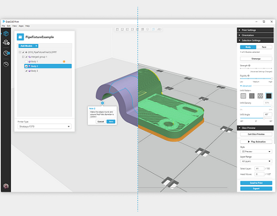
At this week’s SOLIDWORKS World 2019 in Dallas, Stratasys introduced a new feature for its GrabCAD Print software that will remove more complexity from the design-to-3D print process. Advanced FDM will use intuitive model interaction to deliver lightweight yet strong and purpose-built parts to ensure design intent, and is available now via download with GrabCAD Print from versions 1.24 on up. The software feature will help users avoid long, frustrating CAD to STL conversions, so they can work in high fidelity and ramp up parts production, and it also features CAD-native build controls, so no one needs to manually generate complex toolpaths. Advanced FDM can automatically control build attributes, as well as calculate 3D print toolpaths, in order to streamline the process.

“For design and manufacturing engineers, one of the most frustrating processes is ‘dumbing down’ a CAD file to STL format – only to require subsequent re-injection of design intent into the STL printing process. This software is engineered to do away with this complexity, letting designers reduce iterations and design cycles – getting to a high-quality, realistic prototype and final part faster than ever before,” said Mark Walker, Lead Software Product Manager at Stratasys.

America Makes Ultem 9085 FDM Properties in Database

America Makes has announced that its gold-level member, Rapid Prototype + Manufacturing LLC. (rp+m), has created and delivered a complete, qualified database of material properties for the FDM 3D printing of high-performance ULTEM 9085 thermoplastic resin. This comprehensive database, which features processing parameters and both mechanical physical properties, was released to America Makes, and the rest of its membership community, in order to ensure the widespread use of the Type I certified material for 3D printed interior aircraft components. The database is available to the community through the America Makes Digital Storefront.

“The qualification of the ULTEM 9085 material and the establishment of the material properties database by the rp+m-led team are huge steps forward for AM, particularly within the aerospace and defense industries. On behalf of all of us at America Makes, I want to commend rp+m and its team for enabling the broad dissemination of the collective knowledge of ULTEM 9085 for the innovation of future part design,” said Rob Gorham, the Executive Director of America Makes. “The ability to use AM to produce parts with repeatable characteristics and consistent quality for certifiable manufacturing is a key factor to the increased adoption of AM within the multi-billion dollar aircraft interior parts segment.”

3D MicroPrint Identifying Ultra-Fine 3D Printing Powders

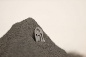
Additive Manufacturing Powder Samples

Germany company 3D MicroPrint uses 3D printing to produce complex metal parts on the micro-scale with its Micro Laser Sintering (MLS) technology, and announced that it is using the FT4 Powder Rheometer from UK-based Freeman Technology, which has over 15 years of experience in powder characterization and flow, in order to push the technology to its limits by identifying ultra-fine metal powders that will process efficiently. The system can differentiate raw powder materials, less than five microns in size, with the kinds of superior flow characteristics that are needed to produce accurate components using 3D MicroPrint’s Micro Laser Sintering (MLS) technology.

“With MLS we are essentially pushing standard AM towards its performance limits. To achieve precise control at the micro scale we spread powders in layers just a few microns thick before selectively fusing areas of the powder bed with a highly focused laser beam. The ultra-fine powders required typically behave quite differently to powders of > 25µm particle size,” explained Joachim Goebner, the CEO at 3D MicroPrint. “We therefore rely on the FT4 Powder Rheometer to identify materials which will perform effectively with our machines, with specified process parameters. Before we had the instrument selecting a suitable powder was essentially a matter of trial and error, a far less efficient approach.”

Discuss this news and other 3D printing topics at 3DPrintBoard.com or share your thoughts below.

Acoustics Play a Role in Determining 3D Print Quality

Metal 3D printing is constantly under study to improve its quality and repeatability. A new research paper focuses on direct metal laser sintering (DMLS), also known as selective laser melting (SLM) and Powder Bed Fusion for Metal. DMLS still has its shortcomings, which include delamination between base plates and inaccuracy among various orientations. The paper, entitled “Characterization of acoustic signals during a direct metal laser sintering process,” points out that sintered parts tend to still be relatively large, soft and porous, hampering their widespread use, so improving part quality and repetability is crucial, especially for industries like aerospace and medicine.

The researchers look at acoustic signal processing as a way to monitor the build quality of a 3D printed part while in progress.

“This paper reports the relationship between acoustic signals, laser power as well as its laser scanning speed,” the researchers state. “The variety of acoustic signal power spectrum density (PSD) is presented and then the mechanism of acoustic signal formation is elaborated. A good mapping between acoustic signals and laser parameters has been found during the DMLS process. This lays a good foundation for monitoring the process and quality by acoustic signal and will enhance the part quality during the powder-based laser sintering and melting processes in the future.”

Several methods of in-process monitoring exist, such as optical, thermal, ultrasound and acoustic signals. Each has its drawbacks, but acoustic signals have been found to be an effective method as long as they are not disrupted by environmental noise. In this study, acoustic signals generated during the DMLS process were sampled and utilized for online monitoring.

Acoustic signals in a DMLS process are generated by several factors, mostly by the vibration from the friction of flow medium with liquid or solid matter, as well as flow motion. The signals in this study were sampled by an electret condenser microphone and processed with MATLAB 2015b.

The results of the experiment showed that there was a good correlation between the laser frequency and laser power as well as the laser scanning speed and acoustic signals.

“Through the investigation of the acoustic signal, information on the laser scanning characteristics can be extracted,” the researchers explain. “The second frequency peak is more promising for detecting the laser scanning attributes.”

The study showed that there was a good mapping between the acoustic signals and laser scanning status as well as the resulting laser sintering quality. These results, according to the researchers, will lead to future monitoring techniques for DMLS and provide a strong foundation for real-time control of metal printing processes.

“Future studies will be carried out on part qualities such as surface roughness, porosity, density and composition of the powder mixture interpreted via acoustic signals,” they conclude. “Defects can be predicted automatically for quality monitoring and feedback control.”

Studies like this one are important steps toward understanding what is happening during the metal 3D printing process, so that defects can be caught and avoided. Metal 3D printing is far from a perfect process, but the more technology is applied to understanding it, the more effective it will be.

Authors of the paper include Dongsen Ye, Yingjie Zhang, Kunpeng Zhu, Geok Soon Hong and Jerry Fuh Ying His.

Discuss this and other 3D printing topics at 3DPrintBoard.com or share your thoughts below.

CT Scanning Proves to be an Effective Method for Qualifying 3D Printed Parts

Many things can go wrong with an additively manufactured part, and those things are not always visible. Particularly in powder-based 3D printing, there are several things that can happen during the print that cause issues such as cracking and voids, which may be inside the part and invisible to the eye. There are ways, however, of discovering these defects without having to break apart the part and look inside. In a new paper entitled “The Role of Computed Tomography in Additive Manufacturing,” which you can access here, a group of researchers argue that computed tomography, or CT scanning, is the most effective way of performing quality checks on 3D printed parts.

Complex parts are especially challenging to inspect for quality purposes, as they can contain internal channels or structures that are prone to voids or inclusions, which are unmelted particles or powder residues. These flaws are difficult for traditional non-destructive testing, or NDT, techniques to fully assess. These techniques include ultrasonic, infrared, eddy current, radiographic inspection, and light-based technologies. Optical methods of defect detection can only detect flaws at the surface or through a surface opening.

“Eddy-current testing and ultrasonic techniques can detect defects within the volume if they are not located very deep inside the testing sample, but the one drawback is the limited spatial resolution of detection, which is in the millimeter range or some fraction of millimeters in the most optimal situations and for even more limited depths into the surface,” the researchers explain.

The best method for nondestructive inspection of complex geometries inside a part, they argue, is X-ray CT, which has a resolution from millimeter to micrometer ranges, and even sub-micron levels in some cases. In fact, they continue, in many cases it is the only viable option. It can detect cracks, porosity, dimensional deviations from CAD models, and powder residues or inclusions.

“In general, tactile CMMs (coordinate measuring machines) or optical measuring instruments like laser scanners are limited to the measurement of the external surface of an AM part and can provide additional measurements for partial qualification of CT measurements,” the researchers add. “In addition, tactile CMMs can produce compressive stresses and friction during sliding that could produce wear at the surface. In contrast, X-ray CT eliminates the above difficulties because it is a non-contact technique that can access internal features.”

X-ray CT analysis of a 3D printed turbine blade

The importance of qualification for additively manufactured parts cannot be overstated. If a part is being used for an aerospace application, for example, it’s absolutely critical that that part is perfect, with no hidden flaws. There are many methods for checking the quality of parts, but most of them come up short in terms of detecting flaws that are hidden deep inside a part. The paper goes on to highlight a case study in which X-ray CT was able to detect minute deviations in dimension from the CAD model to the final part, as well as material inclusions in the internal cavities.

It can be challenging to use CT technology with metal parts, as metal parts can scatter X-rays, disrupting CT reconstructions and producing unwanted artifacts in the data. The solution, the researchers say, is to use a 2D fan beam of X-rays and a linear detector, which can reduce the scattering. Overall, they conclude, CT technology is an effective method of non-destructive testing.

Authors of the paper include Herminso Villaraga-Gómez, Christopher M. Peitsch, Andrew Ramsey and Stuart T. Smith.

Discuss this and other 3D printing topics at 3DPrintBoard.com or share your thoughts below.