Researchers Study Behavior of 3D Printed Geneva Mechanisms

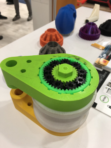
A Geneva drive is a gear that will turn a continuous rotation mechanism into an intermittent rotary motion mechanism by adding a driven wheel to the gear with multiple slots. It then advances a single 90° step each time the drive wheel rotates. Named for its frequent use in Swiss-made watches, it’s still used today in things like movie projectors, and even in 3D printed applications such as novelty items and drug delivery systems.

A team of researchers from the Politehnica of Bucharest University in Romania published a paper, titled “Study behavior of Geneva mechanism using 3D printing technology,” where they considered the use of a variety of materials and technologies for developing, and studying the behavior of, these gears.

The abstract states, “In this paper the authors considered external Geneva mechanism. The design and machining of a conventional Geneva mechanism are generally well known, but there are some particularities, if we consider 3D printing technologies. Conventional, Geneva mechanisms are used to low-speed applications, or to those in which noise and vibration are of no importance. Using PLA+Copper or ABS materials noise and vibrations are reduced considerably. Also, the entire mechanism has a reduced weight. There were considered different fill factors for 3D printed parts. The experimental setup allows fast changing of mechanism parts. This research aims the study of behaviour of 3D Printed machine elements like: springs, bearings, clutches gears, bellows, diaphragms, bushes, brakes, sliders, etc developed by authors.”

A Geneva mechanism is a type of indexing mechanism with a fairly simple design – just a driving crank and wheel, with straight slots. This is known as a Maltese Cross mechanism. Conventional Geneva mechanisms are used for more low-speed applications, where the amount of vibration or noise made doesn’t matter.

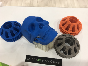
The researchers 3D printed five Geneva mechanisms – each with five Maltese crosses and five driving cranks with pins – out of five different materials:

  • Plexiglass
  • PLA
  • ABS
  • PLA + copper
  • PLA + bronze

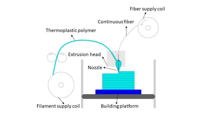
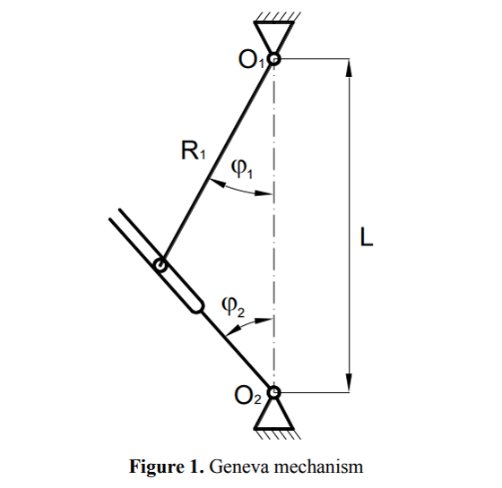
“The Geneva mechanism translates continuous motion to intermittent motion through the driving wheel whose crank pin is shown in figure 1,” the researchers explained. “It drives the Geneva wheel as it slides into and out of the slot of the Geneva wheel. It thus advances it – one step at a time when engaged. The driver wheel usually consists of both the crank and a raised circular blocking disk that locks the Geneva wheel in position between steps to avoid excessive vibration while rotating.”

Each cross had six slots, but a Matlab environment was used to develop a theoretical study that considered different Geneva mechanisms with z = 3, 4 and 6 slots; you can see these results in Figure 2.

Figure 2. Geneva mechanisms position and speed characteristics with different number of slots

The team also created experimental setups for five mechanisms so they could “determine cinematic parameters of Geneva mechanisms.” They used reflective sensors to find the time between two successive slots.

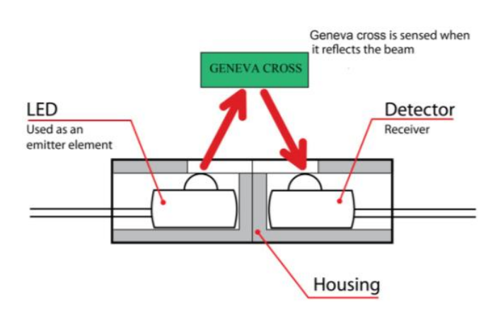
Figure 3. Operating mode of optical reflective sensors

“When the slot of the Maltese cross is in front of the reflective sensor the reflected beam is interrupted,” the researchers wrote. “Then, the cross is rotating with an angle of 60°. The cross passes in front of the reflective sensor and the time is recorded until the next (successive) slot is reached. When the cross is in front of the reflective sensor the beam is reflected.”

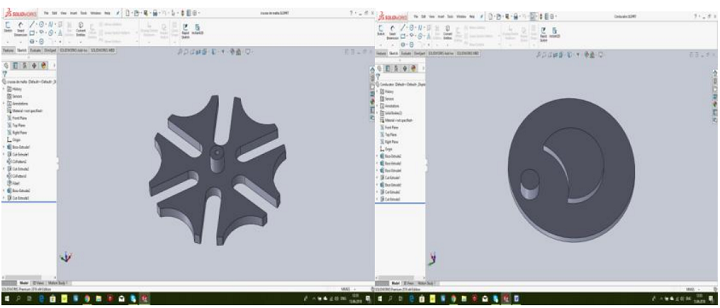
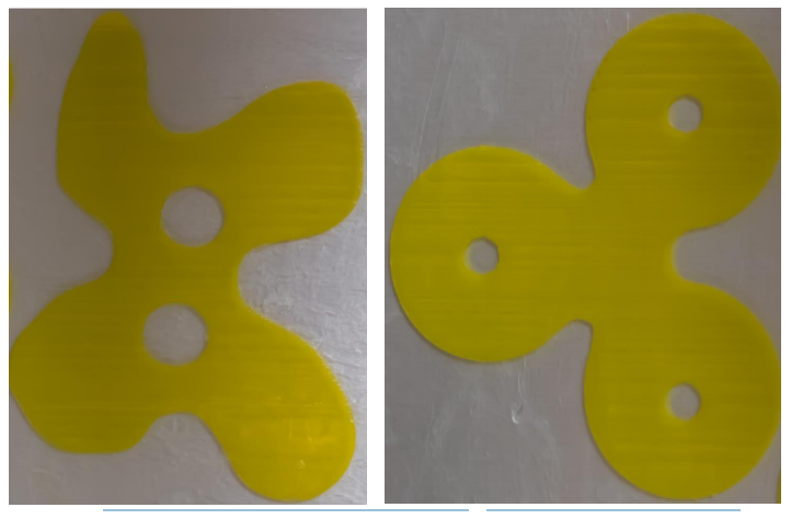
Figure 5. CAD models of Maltese cross

Different angular rotation speeds for the driver crank were also tested for the paper, in order to study the Geneva mechanisms’ cinematic and dynamic behaviors.

The experimental setups with Geneva mechanisms are connected to PC through a USB interface.

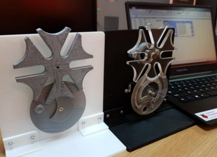
Figure 6. Experimental setups PLA (left) and PLEXI (right)

“The models obtained are used as demonstration stands used in didactic applications,” the researchers concluded. “Of the five investigated materials, ABS and PLA + Copper have been proved to have properties and characteristics close to mechanical engineering applications and these results are demonstrated by graphs. ABS also has the advantage of lighter weight, which makes it suitable for applications where low mass is needed. It can also be concluded that the angular speed of the drive element is inversely proportional to the difference between the angular speeds of the Malta crosses.”

Co-authors of the paper are D. RizescuD. BesneaC.I. Rizescu, and E. Moraru.

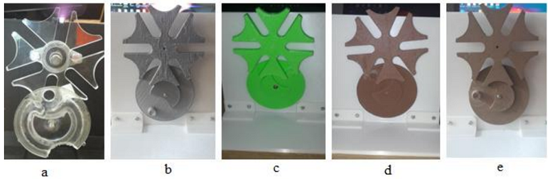
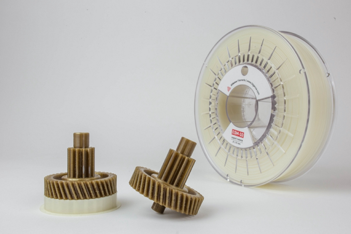
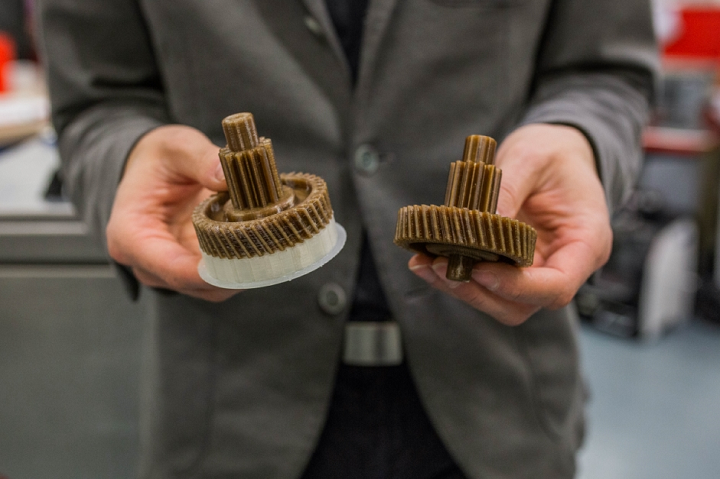
Figure 7. Geneva mechanisms from different materials: a) PMMA b) PLA c) ABS d) PLA + copper e) PLA + bronze

Discuss this story and other 3D printing topics at 3DPrintBoard.com or share your thoughts in the Facebook comments below.


The post Researchers Study Behavior of 3D Printed Geneva Mechanisms appeared first on 3DPrint.com | The Voice of 3D Printing / Additive Manufacturing.

Makerbot Launches Method X Brings Real ABS 3D Printing to Manufacturing

MakerBot, a global leader in 3D printing, announces the launch of METHOD X, a manufacturing workstation engineered to challenge traditional manufacturing with real ABS (acrylonitrile butadiene styrene) material, a 100°C chamber, and Stratasys SR-30 soluble supports to deliver exceptional dimensional accuracy and precision for complex, durable parts. METHOD X is capable of printing real ABS that can withstand up to 15°C higher temperatures, is up to 26% more rigid, and up to 12% stronger than modified ABS formulations used on desktop 3D printer competitors.1 Real ABS parts printed on METHOD X have no warping or cracking that typically occurs when printing modified ABS on desktop platforms without heated chambers.

Desktop 3D printer manufacturers attempt to get around part deformation that occurs, due to the high shrinkage rate of the material, by using a heated build plate in combination with altered ABS formulations that are easier to print but compromise thermal and mechanical properties. MakerBot Precision ABS has a heat deflection temperature of up to 15°C higher than competitors’ ABS, which are modified to make material printable without a heated chamber. With METHOD X, the 100°C Circulating Heated Chamber significantly reduces part deformation while increasing part durability and surface finish.

The MakerBot METHOD X combines industry expertise and technologies from Stratasys® (Nasdaq: SSYS)—the worldwide leader in industrial 3D printing—with MakerBot’s accessibility and ease of use to provide professionals with an industrial 3D printer at a disruptive price point.

MakerBot ABS for METHOD has excellent thermal and mechanical properties similar to ABS materials used for injection molding applications—making it ideal for a wide range of applications, including end-use parts, manufacturing tools, and functional prototypes. A 100°C Circulating Heated Chamber provides a stable print environment for superior Z-layer bonding—resulting in high-strength parts with superior surface finish. With the MakerBot METHOD X, engineers can design, test, and produce models and custom end-use parts with durable, production-grade ABS for their manufacturing needs.

Also new is the availability of Stratasys SR-30 material for easy and fast support removal. METHOD X is the only 3D printer in its price class that uses SR-30—enabling unlimited design freedom and the ability to print unrestricted geometries, such as large overhangs, cavities, and shelled parts. The combination of SR-30 and MakerBot ABS is designed to provide outstanding surface finish and print precision.

“When we initially launched METHOD, we broke the price-to-performance barrier by delivering a 3D printer that was designed to bridge the technology gap between industrial and desktop 3D printers. This made industrial 3D printing accessible to professionals for the first time. Since then, we have shipped hundreds of printers and received positive feedback from a number of our customers on the precision and reliability of the machine,” said Nadav Goshen, CEO, MakerBot. “With METHOD X, we are taking a step further to revolutionize manufacturing. METHOD X was created for engineers who need true ABS for production-ready parts that are dimensionally-accurate with no geometric restrictions. METHOD X delivers industrial-level 3D printing without compromising on ABS material properties and automation in a new price category.”

Engineered as an automated, tinker-free industrial 3D printing system, METHOD X includes industrial features such as Dry-Sealed Material Bays, Dual Performance Extruders, Soluble Supports, and an Ultra-Rigid Metal Frame. METHOD X’s automation and industrial technologies create a controlled printing environment so professionals can design, test, and iterate faster. The lengthened thermal core in the performance extruders are up to 50% longer than a standard hot end to enable faster extrusion, resulting in up to 2X faster print speeds than desktop 3D printers.2

These key technologies—combined with MakerBot ABS for METHOD—are designed to help engineers achieve dimensionally-accurate, production-grade parts at a significantly lower cost than traditional manufacturing processes. Engineers can print repeatable and consistent parts, such as jigs, fixtures, and end-effectors, with a measurable dimensional accuracy of ± 0.2mm (± 0.007in).3

METHOD X can be used with MakerBot’s lines of Precision and Specialty Materials, including MakerBot PLA, MakerBot TOUGH, MakerBot PETG, MakerBot PVA, MakerBot ABS, and SR-30, with more to come.

MakerBot METHOD X’s automated and advanced features provide users with a seamless workflow to help them optimize their design and production processes. The MakerBot METHOD X is one of the most intelligent 3D printers on the market, with 21 onboard sensors that help users monitor, enhance, and print their projects, including RFID chips, temperature sensing, humidity control, material detection, and more. The METHOD platform provides a seamless CAD to part workflow, with Solidworks, Autodesk Fusion 360 and Inventor plug-ins and support for over 30 types of CAD files, helping users turn their CAD files to parts quicker.

The METHOD platform has been tested by MakerBot for over 300,000 hours of system reliability, subsystem, and print quality testing.4

Shipping of METHOD X is expected to begin at the end of August 2019. To learn more about the MakerBot METHOD X, visit www.makerbot.com/method.

1 Based on internal testing of injection molded specimens of METHOD X ABS compared to ABS from a leading desktop 3D printer competitor. Tensile strength testing was performed according to ASTM D638 and HDT B testing according to ASTM D648.
2 Compared to popular desktop 3D printers when using the same layer height and infill density settings. Speed advantage dependent upon object geometry and material.
3 0.2 mm or ± 0.002 mm per mm of travel (whichever is greater). Based on internal testing of selected geometries.
4 Combined total test hours of METHOD and METHOD X (full system and subsystem testing) expected to be completed around shipping of METHOD X.

About MakerBot
MakerBot, a subsidiary of Stratasys Ltd. (Nasdaq: SSYS), is a global leader in the 3D printing industry. The company helps create the innovators of today and the businesses and learning institutions of the future. Founded in 2009 in Brooklyn, NY, MakerBot strives to redefine the standards for 3D printing for reliability, accessibility, precision, and ease-of-use. Through this dedication, MakerBot has one of the largest install bases in the industry and also runs Thingiverse, the largest 3D printing community in the world.

We believe there’s an innovator in everyone, so we make the 3D printing tools that make your ideas matter. Discover innovation with MakerBot 3D printing.

To learn more about MakerBot, visit makerbot.com.

Note Regarding Forward-Looking Statement

The statements in this press release relating to Stratasys’ and/or MakerBot’s beliefs regarding the benefits consumers will experience from the MakerBot METHOD X and its features and Stratasys’ and MakerBot’s expectations on timing of shipping the MakerBot METHOD X are forward-looking statements reflecting management’s current expectations and beliefs. These forward-looking statements are based on current information that is, by its nature, subject to rapid and even abrupt change. Due to risks and uncertainties associated with Stratasys’ and MakerBot’s businesses, actual results could differ materially from those projected or implied by these forward-looking statements. These risks and uncertainties include, but are not limited to: the risk that consumers will not perceive the benefits of the MakerBot METHOD X and its features to be the same as Stratasys and MakerBot do; the risk that unforeseen technical difficulties will delay the shipping of the MakerBot METHOD X; and other risk factors set forth under the caption “Risk Factors” in Stratasys’ most recent Annual Report on Form 20-F, filed with the Securities and Exchange Commission (SEC) on March 7, 2019. Stratasys (or MakerBot) is under no obligation (and expressly disclaims any obligation) to update or alter its forward-looking statements, whether as a result of new information, future events or otherwise, except as otherwise required by the rules and regulations of the SEC.

The post Makerbot Launches Method X Brings Real ABS 3D Printing to Manufacturing appeared first on 3DPrint.com | The Voice of 3D Printing / Additive Manufacturing.

Kodak Launched New Design to Print Service, Showcased 3D Printing Ecosystem

Just a couple of short years ago, Kodak entered the AM market with its 3D Printing Ecosystem, which includes specialized software, the dual extruder, professional Portrait 3D printer, and a line of premium, low moisture content filaments. I learned a lot about this ecosystem while visiting Kodak’s booth at the recent RAPID+TCT show in Detroit, as the Portrait, and a wide array of example prints made on it, were being showcased.

On to new business first – the company launched its new Design to Print Service, which Kodak’s CCO and and co-founder Demian Gawianski told me is helpful for “customers who find designers’ time very valuable.”

“This can go from converting any 3D model into a 3D printable file to tuning the parameters on how to print those files,” he told me. “Basically, if you have complex geometry that wouldn’t go with our preset parameters, because it may have some bridges or overhangs or something like that, we would create the profile for the user, and our designers will actually print out the part to make sure it works.”


The company was offering a launching offer for its new service at the show – any customer who purchased the Portrait 3D printer at RAPID would also receive a $500 credit for the Design to Print Service.

This valuable service is an easy three-step process: first, share your project on your Kodak 3D Cloud account. Then, interact with the company’s professional designers in order to get a quick quote for the project, in addition to an estimated completion date. Finally, have your part optimized for a guaranteed result, printed, and tested by the Kodak team. You will then receive an STL file from the company that’s been modified for successful 3D printing. The service is available in English and Spanish, from 8 am to 5 pm EST, for a standard rate of $45 an hour; a priority job is available for an hourly rate of $90.

“We want to make sure that the user has a very successful experience, with any level of knowledge they may have about 3D printing,” Gawianski continued. “We want to have a comprehensive approach.”

This includes providing users with the right materials and hardware, empowered by good software, and Gawianski believes that Kodak’s design solution offers this unique, comprehensive approach.

Then we moved over to the Portrait 3D printer, which features a compact 215 x 210 x 235 mm build volume with a magnetic, heated build plate and dual extruders. With an intuitive color touchscreen that supports multiple languages, HEPA filter with activated carbon, automatic bed leveling, and live print monitoring via a built-in camera, I can see why Kodak calls it “the new standard for ‘desktop’ professional printing.”

Gawianski noted the “fully enclosed chamber,” which helps enable a “high level of control,” stability, and accuracy. He also pointed out the dual extrusion system with automatic nozzle lifting. The #2 hotend on the left is Teflon for high temperature materials, while the one on the right is metal for lower temperatures. The part being printed while we were standing there was out of white ABS.

“It would be difficult to achieve this level of quality on another printer with ABS, because it would warp and have all kinds of problems,” he explained.

Then we walked over to a setup in the corner of the booth that had caught my eye when I first arrived. A Portrait 3D printer – which was currently operating and weighs about 35 kg – had been placed on a rather thin-looking wooden platform, which was suspended by ropes that were attached to nylon hooks 3D printed on the Portrait itself.


The nylon hooks were strong enough to keep the platform stable, so the print could continue uninterrupted with “the same level of quality” while it was fabricating a blue part out of strong but flexible Nylon 6.

“The printer comes with two filament cases. You open the back of a filament, and place the filament in the case,” Gawianski said. “It has a silica gel that continues to protect the filament all the way from the manufacturing plant to the printed part.”

This case protects the filament from absorbing dust or humidity. Kodak is open to Portrait customers using third party materials, but these clear cases are only for its own filament.


He then started to show me various parts made out of Kodak’s other materials, such as a blue skull printed out of PLA Tough with water-soluble PVA supports, an engineering part made out of ABS with HIPS supports that dissolve in Limonene, and a large part with a green top that can lift 700 lbs of weight.

Kodak offers 11 different materials, including strong, food-safe PETG and semi-flexible Flex 98 with high abrasive resistance. Gawianski brought out a 3D printed part that was a good example of the Portrait 3D printer’s dual extrusion. The figure, which bore a strong resemblance to the Egyptian god Anubis, was made with PLA+ (green) and PLA Tough (red), which are the two materials that come with the Portrait 3D printer out of the box.

“We also have Nylon 12, which is FDA certified and has high resistance to impact,” Gawianski said, showing me two parts in translucent white.

“We also have some further ABS parts – this is a delamination test,” he continued, scratching the side of a small container. “It’s difficult to achieve this with an open printer, you need an enclosed one.”

Kodak will soon be releasing some new materials to the market, such as acrylic, which I also got the chance to see.

Our conversation ended by discussing Kodak’s 3D printing software.

“We have a desktop solution, which is the Kodak 3D Slicer,” Gawianski explained. “And we have the Kodak 3D Cloud, that is a cloud management system that enables you to manage an unlimited number of printers in unlimited locations from a single data place. So from your computer, phone, whatever, you can manage this fleet of printer.”

I asked if the company had anything new on the horizon, and aside from new filaments, Gawianski also said we can expect to see a new 3D printer model by the end of the year.

Take a look at some more of my pictures from the Kodak booth at RAPID+TCT 2019 below:


Discuss this story, and other 3D printing topics, at 3DPrintBoard.com or share your thoughts in the Facebook comments below.

[Images: Sarah Saunders]

Thesis Student Creates Business Case for Desktop 3D Printing E-Cigarette Cases

Thesis student Calvin Smith, at Minnesota State University, brings up a topic most 3D printing enthusiasts and users should be interested in as he explores the limits—and endless possibilities— of desktop fabrication in Developing a Commercial Product Using a Consumer Grade 3D Printer.’ Undeniably, 3D printing has changed the face of production on all levels of industry, from home fashion designs to haute couture, small car parts made in the workshop to myriad prototypes and components now used by automotive leaders, and much more, spanning nearly every industry you can think of. But, how do we go from the 3D printing idea towards practical implementation? Can one really start a business with a desktop 3D printer? What are the costings and what is the business case? Calvin Smith’s research looks into these questions and is a valuable resource for anyone wishing to start a business using desktop 3D printers.

Smith points out that with the self-sustainability afforded through 3D printing, entrepreneurs are imbued with new power to create and sell, and even found their own startups. The desktop 3D printing marketplace is vast, and it is not hard to find the hardware, software, and materials to excel in low-volume manufacturing even from the home. As a good example for the purpose of his study, Smith uses the idea of 3D printed pod cases for electronic cigarettes as a business model that would be feasible, to include designing, manufacturing, and distributing.

Standard types of e-cigarettes (CDC, 2019)

Standard types of e-cigarettes (CDC, 2019)

At the time of this thesis, Smith was actually smoking the Myle brand of e-cigarettes in an attempt to quit smoking regular cigarettes. In terms of a business development plan, to include the cases, Smith studied the potential with Myle and Juul. Along with pinpointing the best 3D printers for small businesses (Prusa I3 MK3, MakerBot Replicator, and Lulzbot TAZ 6), along with ABS and PLA as the most affordable materials, Smith moved on to breaking down costs (see the table below).

Intellectual property protection was an obvious concern, and Smith was surprised to find out the costs and complications associated with filing a patent—as are many individuals in the US. While it can be critical to protect your inventions, it is often cost-prohibitive too.

“While research was conducted on the patent application, life span and earning potential of the product a temporary provisional patent was filed so the design would have an official timeline attached to it,” stated Smith. “This patent-pending status is easy to file and has a filing fee of $147, patent-pending status is considered active for 1 year from the date the application is filed and can be converted to a complete patent any time during that 1 year. The patent-pending status does not give any protection to the design however it does give an earlier filing date.”

This was a smart move considering the rapid acceleration of the e-cigarette market and the length of time it takes to be approved for a patent (or find out that you have been declined), which can be 18 months to two years in many cases.

They then moved on to creating the cigarette pod cover case for 3D printing in PLA on the Prusa MK3.

“The goal for the size of the case with device and pods was to be 50% smaller than a pack of traditional cigarettes which measures 3.5” tall by 2.125” wide and 0.875” thick,” stated Smith.

Design V1.0

The first 3D design was functional and ‘worked as intended,’ but not without some kinks that needed to be worked out as there was not an area to charge the e-cigarette, and it was also difficult to remove the extra cigarette pod from the bottom due to lack of a good grip.

“This case was printed using PLA (Polylactic Acid) plastic which is the standard 3d printing plastic because it is renewable, biodegradable, cheap, has minimal warping, easy to print, and high strength,” stated Smith. “The downfalls to printing with PLA is it is brittle, and due to its glass transition temperature or temperature when the material becomes soft enough to flow, it does not hold shape in hot environments.

The first case took 45 minutes to print and used 6.8 grams of material—at a cost of 17 cents per case.

“ABS is stronger than PLA, less brittle, and still cheap. It has the added benefit that ABS can be vapor polished using acetone, this smooths the part giving it a better visual appearance and makes it stronger by increasing the layer adhesion,” said Smith.

The second 3D case design was refined to solve the previous problems, and they also tried using ABS instead. It took much longer to print at a total of 160 minutes, but with the same cost of 17 cents; however, problems with cracking proved the design to be problematic later.

Their next, and successful, design (Version 2.4) occurred with NinjaFlex, printed in 52 minutes, consuming only 11 grams of material—but at an increased price of $1.22 per case.

“The cases must be printed one at a time to obtain the best surface finish and to minimize material stringing. This design and process allows to produce up to 12 cases per day, with a single printer and operator taking into account for other work, errors, and miss prints 50 cases per week can easily be printed,” stated Smith.

There was also one more iteration ‘reworked for manufacturability’ that could also be made through traditional injection molding processes, and could still show promise for the future.

“Version 2.4 of the Pod Case was the final developmental stage for 3D printing of the Pod Case, this design was approved by the stores interested in carrying the case and the distributer who was interested in the case for wholesale. The cost to produce a Pod Case via 3D printing is estimated at $3.00. The cost to retail outlets of the finished case with packaging was $5.00 per unit with the capacity to deliver 50 units per week and a retail sale price of $10.00. This price point and production capacity makes the case too expensive for wholesale distributers, however there is still research being done to make V2.4 via injection molding and estimates at time of writing this thesis show cases could be manufactured, packaged, and delivered for $1.25 per unit with a wholesale cost of $3.00 per unit. There must be a market to sell 5000 units minimum to continue research into mass production via injection molding,” concluded Smith.

“The possibility to earn extra income from 3D printing is very realistic with minimal labor involved. Overall there was strong profit margin in small scale manufacturing and prototyping as the labor involved only includes basic setup and design time while the printer can run unsupervised for the majority of time involved,” concluded Smith.

Most makers are habitual rule-breakers when it comes to 3D printing. If a material or technique is designated for a particular level or limit, be assured they will soon be using it to innovate far beyond what the developer originally intended—whether showing off with a 3D printed car engine or transmission or even a tiny home.

What do you think of this news? Let us know your thoughts! Join the discussion of this and other 3D printing topics at 3DPrintBoard.com.

[Source / Images: ‘Developing a Commercial Product Using a Consumer Grade 3D Printer’]

Istanbul: Thesis Student Explores Continuous Fiber Composites in FDM 3D Printing

Although polymers are still the most popular materials used in 3D printing today, many users find themselves limited due to issues with inferior strength and rigidity. Creating composites is a good way to solve these problems, allowing manufacturers to enjoy the benefits of existing plastics while reinforcing them for better performance. In ‘Modelling and path planning for additive manufacturing of continuous fiber composites,’ Suleman Asif, a thesis student at Sabanci University (Instanbul), examines how the addition of continuous fibers can improve fabrication processes with thermoplastic polymers, and add greater strength in mechanical properties.

FDM 3D printing is mainly explored here. Issues with FDM 3D printing and these materials, however, tend to be centered around a lack of strength and inferior surface finish, build times that take too long, and inconvenient post-processing. In previous studies, researchers have used short fibers to strengthen thermoplastics, along with carbon nanotubes and fiber composites. Iron and copper have been added to ABS, and the addition of graphene fibers have been noted to add conductivity. In most cases, tensile strength increased but there were issues with interfacial bonding and porosity.

The use of short fibers and nanofibers has been explored, but Asif explains that such additions are better for applications like aerospace or automotive. With the use of continuous fiber reinforced thermoplastic (CFRPT) composites, though, both ‘ingredients’ are extruded at the same time from one nozzle and show significant improvement and strengthening.

Schematic diagram of 3D printing process with continuous fiber composite

In a different study, researchers loaded both thermoplastic polymer and continuous fibers into the nozzles for FDM printing, with PLA and continuous fibers (some samples consisted of carbon fibers, and some with jute) added separately to another nozzle. While carbon did offer improvements in strength, the jute was not helpful due to ‘degradation of fiber matrix interactions.’ Other tests showed that PLA reinforced with modified carbon showed higher tensile and flexural strength values, demonstrating how powerful ‘preprocessing’ can be.

“Furthermore, a path control method was developed to print complex geometries including hollow-out aerofoil, a unidirectional flat part, and a circular part,” states Asif.

Previous methods also used ABS and carbon fibers, with two different nozzles and the carbon fibers contained in between the upper and bottom layers of the plastic.

“The process worked in such a way that after printing of lower layers of ABS, carbon fibers [were] thermally bonded using a heating pin before the upper layers of ABS were printed. In addition, some samples were also thermally bonded using a microwave to understand the difference between both methods,” said Asif.

In comparison to pure ABS, the results demonstrated significant strengthening in mechanical properties.

“In addition, it was observed that there was not much difference between the results obtained from test specimen thermally bonded by heating pin and microwave oven. So, it was concluded that microwave could be successfully used for thermal bonding between matrix and other fiber layers.”

Researchers also attempted to reinforce PLA with aramid fibers, showing ‘notable enhancement.’ Another test evaluated a raw material of commingled yarn, containing polypropylene (PP):

“A cutting device was also incorporated in the system, and a novel deposition strategy was developed. The results showed a remarkable increase in flexural modulus as compared to pure PP. However, the void presence in the samples was a major issue in the proposed technique.”

Overall, in reviewing the multitude of studies performed, Asif saw potential for improving mechanical strength, but realizes a need for control of the fiber position within the nozzle to reduce adhesion issues.

“The system also needs to be designed in such a way that the fiber lies directly in the center of the nozzle to ensure that the thermoplastic polymer is properly diffused into the fiber from all sides using a coaxial printing process in which more than one materials are extruded simultaneously through a nozzle along a common axis,” says Asif.

The researcher also began examining various path planning processes for acquiring point locations that guide the extruder in depositing materials for filling layers. Asif discovered that most suggested path planning was limiting as it only worked for specific complex structures—some of which would not be appropriate for fabrication of CFRTP composites. Asif suggests that as the algorithms stand currently, there would be problems due to:

  • Under-deposition (typically called underextrusion in FDM)
  • Over-deposition
  • Movement of the extruder to next layer after filling one layer

Coaxial CFRPT printing and composite structure with unit cell

“Hence, there is need of a continuous path planning method that can generate a deposition path without any under-deposition and over-deposition, and with better moving strategy from one layer to the next one,” concludes Asif.

“As a future work, a screw-based mechanism can be designed and developed for 3D printing of CFRTP composites. It would allow the continuous input of thermoplastic pallets and, therefore, parts with large dimensions can be printed. In addition, a topology optimization based algorithm can be developed to control the number of layers containing fibers to produce optimized lightweight parts depending upon specific load applications.”

3D printing offers an infinite amount of opportunity for designers and engineers around the world, immersed in creation—whether that is industrial, artistic, or completely scientific. There is an immense amount of energy centered around this technology that just continues to grow in popularity, and especially as users continue to refine the processes and materials. Composites are often used to strengthen existing methods and materials, whether in making structural parts for aerospace, regulating electrical composites, or studying conductivity and different techniques for fabrication. Find out more about the use of continuous fiber composites here.

What do you think of this news? Let us know your thoughts! Join the discussion of this and other 3D printing topics at 3DPrintBoard.com.

Effect of nozzle diameter on the elastic modulus of continuous fiber composites

Implementation of the developed algorithm on a commercial printer (a) Complex concave geometry (b) Fidget spinner

[Source / Images: ‘Modelling and path planning for additive manufacturing of continuous fiber composites’]

International Researchers Review Methods for 3D Printing Biomedical Sensors

Researchers from both China and India have come together to review the current 3D printed sensor scene, regarding the technology being used and applications and industries being impacted. Authors Tao Han, Sudip Kundu, Anindya Nag, and Yongzhao Xu published their findings recently in ‘3D Printed Sensors for Biomedical Applications: A Review.’

While manufacturing of sensors has continued to progress, obstacles have prevailed, and in many ways have stalled sensor fabrication from achieving its true potential in many applications. As the authors point out, sensors are all around us, but many are limited due to the cost involved in manufacturing, challenges regarding materials (such as silicon, also posing problems at low frequencies), and issues with temperature. More importantly, most sensors are not biocompatible, thus stilting advances in the medical arena.

With the advent of 3D printing, sensors can be designed in a more streamlined and affordable process, involving less steps in production and less hours needed in labor for creating accurate prototypes that can then be made digitally. 3D printed sensors are usually much stronger and more durable too and have shown promise for monitoring blood pressure and heart rate, respiration, temperature, brain activity, and more.

(A) Fused deposition modelling (B) Stereo-lithography (C) Polyjet Process (D) Selective laser
sintering (E) 3D Inkjet printing (F) Digital light processing.

Currently, the following processes have been used to make sensors successfully:

  • Fused deposition modelling (FDM)
  • Stereolithography (SLA)
  • Polyjet process
  • Selective laser sintering (SLS)
  • 3D inkjet printing and DLP

“Among these six types, the most common type is the FDM one, which has been largely used to develop prototypes for electrochemical sensing purposes,” state the researchers. “Others like FDM, SLA and ink-jet printing have also been considered for forming prototypes since they can be developed with lower resolutions. Polyjet and SLS processes are mostly used for forming sensors which are employed for cell culture applications.”

FDM 3D printing has been popular among users for biomedical uses, with both AB and PLA materials, as well as alternatives like waxes and nylon. Bioprinting has also been successful, with researchers noting good cell viability and sustainability. The authors note, however, that disadvantages in using FDM 3D printing include lack of shape integrity and leakage when materials are not ‘properly tuned.’ Sensors have, however, been created for detecting glucose, cancer biomarkers, and other items like reactors for biological sample monitoring.

SLA 3D printing is useful due to its ability to create large-scale items. Researchers have used ABS to create more complex devices like biosensors and microfluidic devices for detecting pathogens. Disposable and portable electrochemical sensors have also been created, along with intricate components like a 3D printed microfluidic part for urinary protein quantification, comprised of a pushing valve, rotary valve, and torque-actuated pump.

a) Schematic illustration of separation of the captured bacteria by inertial focusing. (b)
Representation of dean vortices in a channel with trapezoid cross-section. (c) Photograph of the 3D
printed microfluidic device. Reproduced from Lee et al. [112].

In polyjet printing, a curing or hardening process creates parts—and like in FDM 3D printing, multiple nozzles can be used.

“Since multiple jetting heads are used for printing, this allows building multi-colored objects in a single structure. One of the main advantages of this process is that a high resolution of 16 µm can be achieved for the prototypes, having an accuracy of less than 0.1 mm.”

Using polyjet 3D printing, cell viability sensor-based fluidic devices have been created, along with other innovations such as leak-proof 3D printed storage devices. Other sensors have been created through polyjet 3D printing for ATP and dopamine sensing, along with physiological sensors, and electrochemical and biocompatible sensors.

SLS printing is used in AM processes with the use of metal powders:

A certain laser power is required to melt the periphery of the particles using the localised energy of a laser beam. The unused powder acts as a support structure for the 3D printed part. After scanning each layer, the structure is lowered to spread a new powder layer which can be scanned according to the computer-aided design (CAD) design. Not only metallic powder particles but also ceramics and polymers or combinations with each other can be used in SLS,” state the researchers.

Benefits in SLS 3D printing are that many different materials can be used—and precisely so—with powder available for recycling. Cell density sensors have been created, explain the authors, and they could be extended to manipulate cell ‘disruptions,’ distribute chemicals, and control enzymatic assays.

. Continuous recalibration of the 3D-printed Control Unit Adaptive P controller. Reproduced from Ude et al. [127]. (A) The 3D printed flask is used to control the pH of the solution using defined algorithm. (B) The interior of th3 3D printed flask. (C) Variation in the amplitude, pH levels and intensity of the scattered light with time.

3D inkjet printing offers benefit in creating strong, complex structures; for example, researchers have been successful in creating items such as a 3D printed bionic ear. Others have created items like actuator integrated heart structure-shaped 3D elastic multifunctional biomembranes for sensing spatial and temporal responses.

Image of the (A) fabricated 3D printed bionic ear and (B) 3D printed bionic ear during its vitro culture. (C) The viability of chondrocyte at different stages during the printing process. (D) Deviation of the weight of the printed ear over time in culture, where the ear consisted of the chondrocyte-seeded alginate or only alginate shown in red and blue colour respectively. (E) Histologic analysis of chondrocyte morphology done using H&E staining. (F) Neocartilaginous tissue
being Safranin O stained after 10 weeks of culture. Photographs (top) and fluorescent (bottom) images of (G) viability of the neo cartilaginous tissue being in contact with the antenna of the coil and (H) cross-section of the bionic ear showing the viability of the internal cartilaginous tissue in contact with the electrode. Reproduced from Mannoor et al.

DLP 3D printing is like that of SLA, but a projector screen flashes, projecting layers like images:

“Each 2D hardened layer is formed after exposing the liquid polymer to projector light under the safest conditions instead of making a layer with several laser scan paths,” state the researchers. “The process is repeated until the entire structure is fabricated.”

Items such as glucose biosensors, light-addressable potentiometric sensors, and semiconductor-based biosensor are a few devices that have been created so far with DLP 3D printing.

“Each of these processes has its own merits and demerits related to cost and time of fabrication, the type of materials that can be processed and prototypes that can be formed,” concluded the researchers. “A few of the current bottlenecks have also been mentioned, along with the possible remedial solutions to deal with them. Finally, a market survey has been presented about the expenditures on the different types of 3D printing techniques in the current scenario and in the upcoming years to develop sensors and other electronic appliances.”

3D printing has made a significant impact in the realm of electronics, however, and even more specifically, sensors. Over the years, we have followed a wide array of sensors created to improve monitoring and functionality in numerous applications, from fending off 3D printing cyberattacks to fabricating fiber optics or tending to simple but scientific matters like measuring the water intake of plants. What do you think of this news? Let us know your thoughts! Join the discussion of this and other 3D printing topics at 3DPrintBoard.com.

(a) A 3D printed smartphone adaptor depicting its (b) 3D printed cartridge being composed
of reservoirs and sliding lid. (c) The assembled smartphone-based device for BL signal acquisition
and analysis. Reproduced from Cevenini.

[Source / Images: 3D Printed Sensors for Biomedical Applications: A Review]

ABS: Researchers Test Temperature & Speed Settings in FDM 3D Printing

In ‘Layer-to-Layer Physical Characteristics and Compression Behavior of 3D Printed Acrylonitrile Butadiene Styrene Metastructures Fabricated using Different Process Parameters,’ Wright State University researcher Sivani Patibandla investigates how well ABS performs under pressure, measuring varied responses to temperature and speed, using a MakerBot 2X Replicator 3D printer.

Fabrication of phononic metastructures (often lattice or periodic structures) was examined in comparison to a multitude of previous studies regarding materials and 3D printing, as Patibandla used FDM 3D printing for this study employing several different types of hardness tests. Nine different 3D printed cubes were produced with 50 percent infill density using three different speeds. Samples were created in SolidWorks, fabricated on the MakerBot, and then compression tests were performed using INSTRON 5500R.

“Stress-strain curves are plotted for the samples and the modulus, yield and failure stress are compared. The physical characteristics such as the shape and the size of printed fibers in each layer, the fiber distance, and the fiber-to-fiber interface are investigated,” states Patibandla in her thesis. “In addition, their effects on mechanical characteristics of 16 of the printed samples are examined and interpreted with respect to the layer physical characteristics. The hardness test is done by using MICROMET 1 with a load of 25gf. The micro indenter is indented at contact of the fibers from top and cross section for all the samples to compare their effects with change in fabrication temperature and fabrication speed.”

Schematic diagram of FDM process

Each cube had a build size of 30 mm × 30 mm ×30 mm, with side shells removed via milling so that research could be more easily performed—ultimately resulting in dimensions of 24 mm × 24 mm × 30 mm. Patibandla points out that they were able to vary the following variables:

  • Print fabrication speed
  • Extrusion fabrication temperature
  • Infill percentage
  • Infill geometry
  • Layer thickness
  • Other parameters

Parts were built at temperatures of 210˚C, 230˚C, 250˚C and fabrications speeds of 100 mm/s,125 mm/s, and 150 mm/s. The cubes were viewed from the top using three different magnifications of 6.3, 18, and 20.

“For each sample, the readings are taken at 6 different locations and average value is considered to understand uncertainty. From the measured values it was observed that there is a large gap between the fibers at low fabrication temperatures and the gap decreased with increase in fabrication temperature,” stated the researcher.

Cross sections were also viewed at magnifications of 10,16, and 18. Patibandla noted that fibers from low fabrication temperatures seemed more uniform than those 3D printed at high printed temperatures. Compression testing was performed under displacement control of 0.5 mm/min, with each sample compressed up to 15 mm crush length, at 50 percent of heights.

Stress-strain curves were plotted to find the following:

  • Modulus of elasticity
  • Yield strength
  • Failure strength

Vickers hardness test

In evaluating hardness, the Vickers test was used on all the samples.

“The first set of specimens were indented with a load of 25 gf from top at 3 different locations and the average value of results is taken to get accurate results. Whereas the second set of samples are indented with the same load of 25 gf from the cross section at the intersection point of the fibers. The test is done at 3 different locations and average value considered as the result. Since the surface is not flat while indenting from the top, only the length of indentation in the fiber length direction is recorded that is a function of hardness,” stated Patibandla.

In using three different 3D printing speeds at 100 mm/s, 125 mm/s, and 150 mm/s, the modulus increased as temperature increased from 210 ˚C to 250 ˚C.

“The maximum value is observed for condition 9 which Yield Strength Failure Strength 51 is at a fabrication temperature of 250 ˚C and minimum value at 210 ˚C. The maximum modulus of elasticity is about 321.8 MPa and minimum is 179.1 MPa. It is observed that there is a large increase in modulus from 210 ˚C to 230 ˚C of about 56.7% whereas a small increase of 14.6% from 230 ˚C to 250 ˚C,” said Patibandla.

All results pointed toward more yield and failure strengths in the presence of higher temperatures. The research also showed that speed did not affect any mechanical characteristics.

“From observing all the results and comparing them it is concluded that higher the fabrication temperature better the mechanical properties, and vice versa. However, the printed fibers are more uniform and well-rounded at lower fabrication temperature. It is also observed that the fabrication speed has no effect on any of the physical or mechanical characteristics,” Patibandla concluded.

“In case of physical characteristics from the optical microscopic images and measurements it is clear that at high fabrication temperature the distance between the fibers is less and more at low fabrication temperatures. It is concluded that to get the good or high mechanical properties high fabrication temperatures are preferable. Low fabrication temperatures can be used for acoustic type applications because of their uniformity.

What do you think of this news? Let us know your thoughts! Join the discussion of this and other 3D printing topics at 3DPrintBoard.com.

WARNING: We do wish to point out a word of warning here. Your actual printing temperature may be different from the one indicated. It is not uncommon to find desktop 3D printers that are printing +/- 20 Degrees C from their indicated temperature. The cause of this could de a number of things but it mostly related to the fact that many manufacturers do not test for the actual nozzle temp per individual unit using an external temperature probe (eg an infrared thermometer). This combined with the variability of mounting of temperature sensors on the head leads to differences between units. This means that printing at 240 C may actually mean that you may be printing at 260 or above. With 3D printing, in general, we would suggest that you use a fume hood to reduce the harmful chemicals and particles that you may inhale. Specifically, when printing right below, around or at the degradation temperature of any material we would urge caution. With ABS the thermal degradation temperature is around 260 C which means that an indicated print temperature on your printer of 240 C or above may actually mean that you are processing at 260 C and the ABS compound will at this temperature be releasing gasses such as but not limited to HCN. HCN or Hydrogen Cyanide is an extremely poisonous substance and contact with it should be avoided at all costs. We would urge all 3D printer users to use an external unit to measure actual nozzle temperature and to obtain a fume hood before printing. You wouldn’t want to drive your car without knowing what speed you’re going at.

Additional Reporting by Joris Peels (eg annoying but important warning)

[Source / Images: Layer-to-Layer Physical Characteristics and Compression Behavior of 3D Printed Acrylonitrile Butadiene Styrene Metastructures Fabricated using Different Process Parameters]

Georgia Tech Research: Desktop FDM 3D Printing Particle Emissions May Be Dangerous to Humans

Sometimes 3D printing may seem to be almost too good to be true, offering what can sometimes be astounding benefits in affordability, production of speed, self-sustainability, and savings in materials and labor. The downsides are few, but as with the use of any machinery, the topic of safety should always present. And although physical hazards may be few in 3D printing, toxicity to humans has been in question for years—in connection with both the materials being used and particle emissions.

As Qian Zhang, a PhD student at Georgia Institute of Technology, asserts in her recent dissertation, ‘Particle Emissions from Consumer Level 3D Printers,’ concerns continue regarding 3D printing emissions in closed environments (which would be the norm in most cases) such as the workplace, classroom, and home. Zhang’s research was comprehensive, focusing on ABS and PLA in terms of particle emissions and their dangers to the public.

Overall, as Zhang points out, ABS and PLA are the most common forms of materials used with 3D printing although many other alternative sources are beginning to gain traction too, from metal to wood—and a growing multitude of other options. ABS is used due to affordability, good strength, stiffness, and more, while PLA (although less stable and not as strong) is thought of as being more environmentally friendly due to its plant-based origins, allowing for more recycling options. Zhang considered these materials specifically, along with FDM 3D printers at the desktop level that may emit particles and volatile organic compounds (VOCs or total volatile organic compounds, TVOCs) into the air, along with gas phase pollutants.

Previous studies showed that ABS usually emitted more particles; in fact, perhaps as much as ‘one to two orders of magnitude higher’ than PLA. As the researcher points out, particle emissions can vary due to other reasons such as:

  • Types of environment
  • Air mixing and air rate
  • Measurement instrumentation
  • Calculation methods regarding particles

Particle number (a), surface area (b) and mass (c) emissions for ABS
filament d green color on printer A for 3 objects taking about 1 hr, 4 hr and 7 hr to
print. Each bar indicates the emission (TP) from one print object; colors indicate
different particle size ranges. Values on the colored bars are the ratios of emissions
from such particle size range over total emissions.

Carbon and oxygen were the ‘most abundant elements’ found in particle emissions, along with small amounts of metals. ABS filaments were also known to emit styrene and ethylbenzene, while PLA filaments have been known to emit lactide, lactic acid and methyl-methacrylate. The research shows that overall, VOC concentrations may be above normal limits in offices, but environmental variables such as heating, and air-conditioning, may be responsible for lowering levels of toxins substantially. Ultrafine particles are extremely mobile and may cover a large surface area, and in humans can affect the entire respiratory tract, as well as organs and cells, via transportation through the bloodstream.

“The existing results revealed the potential health effects for 3D printer emissions, while more toxicity assessments using multiple methods need to be applied and compared in order to have a broader understanding of the particle emission toxicity,” states Zhang.

Testing included an examination of the following:

  • Methods
  • Printer operating conditions
  • Printer brands
  • Filament materials
  • Brands and colors
  • Extrusion and build plate temperatures

“Applying an existing test method to 3D printers gives insight for development of a standard test method for 3D printers and provides a database for assessing emission limits. Furthermore, it might provide insights for 3D printer and filament manufacturers to produce low emitting products and develop effective mitigation methods,” says Zhang.

Particle emissions tend to be greater as a 3D printing job begins, mainly comprised of ultrafine particles and nanoparticles.

“For shorter print jobs, these aerosol dynamic processes may never reach steady state before printing ends, whereas for longer jobs, concentrations of various sizes can remain relatively constant after about 1 hour of printing (for this condition), indicating the processes of particle formation, vapor-condensational growth, coagulation and loss reach a steady state,” states Zhang.

“Compared to number concentration profiles, the surface area and mass concentrations both take longer to reach a maximum. The large number of newly formed particles contributes little to surface area or mass, but as printing continues to supply vapors, particle growth by condensation of vapors leads to a rise in surface area and mass concentrations.”

Printer brands and filaments especially did make a big difference when using ABS, while in terms of PLA the 3D printer used had the most effect. ABS numbers turned out to be up to 3 to 104 times that of PLA yields, but Zhang points out that variations differ regarding 3D printer brands, and mass basis of particles should be taken into account also.

 “A consistency among various methods showed that PLA emitted particles induced similar levels of responses at much lower doses than ABS-emitted particles, indicating PLA emitted particles are more toxic on a particle mass basis. However, calculations for the overall exposure showed ABS filaments may be more harmful due to their much higher emissions. Overall, 3D printers are sources of high levels of ultrafine particles, which are potentially harmful for their users. Therefore, the emissions should be regulated and mitigate,” concluded the research.

What do you think of this news? Let us know your thoughts! Join the discussion of this and other 3D printing topics at 3DPrintBoard.com.

[Source / Images: Particle Emissions from Consumer Level 3D Printers]


Time series of particle number concentrations averaged over various
particle size ranges on log scale (a), total particle concentrations on linear scale (b),
evolution of size distributions (c) and average particle number distributions during
the printing period separated into 5 time intervals (d). The print condition was ABS
filament brand a, red color, using printer A; the printing period was 47 min,
identified by the vertical lines.

Long time print job time series of particle number concentrations (a) and size distributions (b) for ABS filament, brand d, green color, on printer A; the printing period was 7 hr 4 min, identified by the vertical lines.

Fillamentum launches ASA 3D printer filament made for more than just the outdoors

Popular 3D printer materials brand Fillamentum has launched three new shades of its ASA Extrafill filament for FFF/FDM. Noticing a rise in users switching from ABS to the higher resistance thermoplastic, the company states, “ASA is getting really popular among designers, and that happens for its properties. ASA is optimal for outside usage but its […]

3DGence Introduces ESM-10 Soluble 3D Printing Support Material for PEEK and ABS Models

Polish 3D printer manufacturer 3DGence, a third wave 3D printing company, has just launched a new product that’s really cool: ESM-10 (Engineering Soluble Material), the first soluble support material for PEEK 3D prints.

“An introduction of the ESM-10 is a milestone not only for 3DGence but also for the entire 3D printing industry,” said Mateusz Sidorowicz, the Marketing Manager at 3DGence. “Soluble support filament for technical materials creates new opportunities, especially for industrial companies. Creating prints with advanced geometry and large dimensions is now easier.”

PEEK part with ESM-10 supports

Before now, PEEK-friendly support materials cost a lot of money, and were pretty difficult to remove from prints. Most people were just using PEEK as a support material for PEEK. Depending on the grade this could cost $600 or more per Kilo and be difficult to remove as well. But ESM-10, just one in a series of advanced engineering filaments that are used to create complex 3D prints with necessary complex supports, uses a heated chamber – above 80°C, to be exact – to ensure the support structure’s stability for models made with both PEEK and ABS materials.

The ESM-10 support material, which can be easily washed out in a prepared water solution, is designed for technical applications and is compatible with the 3DGence INDUSTRY F340 industrial 3D printer.

While ESM-10 is recommended for ABS and PEEK model materials, this is not the case for PLA filament; it’s much better to use soluble materials like PVA or BVOH with the popular plastic.


ESM-10 is able to endure, as 3DGence puts it, “the temperature of the working chamber in which it can be printed,” and the material won’t clog up any hotends or recrystallize, since it can be 3D printed at higher temperatures. Because of its unique features, the soluble material can also be used as a support for prints made out of more technical materials where options like BVOH or PVA can’t be used.

In addition to its new ESM-10 support material, 3DGence has also introduced its SDS, short for Support Dissolving System: a circulation tank that was designed specifically for the purposes of dissolving the supports from 3D prints.

“SDS is dedicated to removing support structures from 3D prints made of PEEK or ABS. Its greatest advantage is that it eliminates the need for manually removing supports,” said Filip Turzyński, the Quality Development Manager at 3DGence. “Thanks to this solution we can be sure that the printed model will not be damaged in any way. In the automated rinsing process we can obtain a clean model free of supports, which is fully functional.”

The SDS machine includes a large, actively heated working chamber, which has a total capacity of 55.2 liters, and also comes with a 36 x 36 x 28 cm basket for 3D prints that allows larger models to be totally immersed in a water solution in order to rinse away the supports. Both the heating system and the device’s insulation ensure that the temperature inside is well-suited to efficiently remove support materials.

Users need to pour a dedicated chemical solvent into the SDS circulation tank, which will effectively dissolve the ESM-10 support material without causing any damage to the 3D printed model’s material. Because the water system is connected to the water pump, it’s very easy to fill and empty the SDS, and you can safely discharge the combined chemical solution and dissolved ESM-10 material into the sewage system once rinsing is complete.

This once again validates the space increasingly occupied by third wave companies who are going further than just the box. 3DGence is not looking at just the printer they’re looking at the materials, settings and even post-processing equipment to expand the makable. This kind of careful consideration will expand the sum total of the makable and increase what can be made using our technology.

Discuss this news and other 3D printing topics at 3DPrintBoard.com or share your thoughts in the Facebook comments below. 

[Images provided by 3DGence]