MULTI-FUN Consortium Aims to Improve Metal 3D Printing

As the focus continues to shine on metal additive manufacturing (MAM), 21 partners are coming together from eight countries (Austria, Switzerland, Germany, Spain, United Kingdom, Poland, Portugal and Belgium) in a three-year, multi-tiered project to advance AM processes, materials, and equipment for multi-material parts.

Dubbed MULTI-FUN, this long-term endeavor will solve issues in metal printing with powder bed fusion, where only basic alloys are available. Overall, key performance indicators expected are improvement in AM products by 40 percent, better use of resources and with smaller environmental footprint, and the emergence of greater potential and opportunities for businesses in Europe.

The consortium members involved plan to refine 3D printing with metal using new active and structural materials like aluminum and low-alloyed steel for wire arc additive manufacturing (WAAM). They also plan to design complex parts without any restrictions due to size—whether printing on the nano-level or the large scale.

Research into the use of nano-materials spans studies from integration of conductive materials into textiles to economic analysis of nano-metals within a wide range of applications—including critical industries like automotive and aerospace. In the MULTI-FUN project, the researchers will explore nano-materials further, integrating them into thermal materials, electronics, sensors, and more as four different objectives are explored:

  1. Development of five new materials (with at least three related to nanotechnology), customized for AM processes.
  2. Study of new processes and development of AM hardware and software for the production of desired materials. The consortium has outlined a plan for a minimum of ten new materials combinations using five new materials to be displayed by seven demonstrators engaged in different applications.
  3. Manufacturing and evaluation of seven physical demonstrators using multiple materials and functionalities. Three use cases in the areas of structural parts, molds, and testing equipment will serve as examples to show the potential in four applications like automotive, aeronautics, space, and production.
  4. Ongoing evaluation and improvement in AM processes in regard to the economy and the environment, use of materials, strategies, and demonstrator design—ultimately all leading to better standards and support of necessary regulatory bodies.

Consortium members follow.

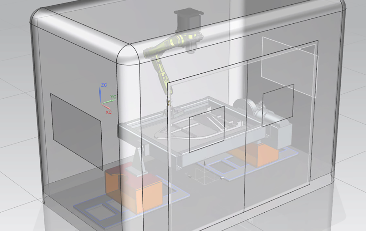
A turnkey solution from WAAM3D (Image: WAAM3D)

[Source / Images: Chronicle]


The post MULTI-FUN Consortium Aims to Improve Metal 3D Printing appeared first on 3DPrint.com | The Voice of 3D Printing / Additive Manufacturing.

Testing the Strength of Hollow, 3D-Printed PLA Spheres

Researchers from Romania have studied the mechanical properties of parts fabricated from polylactic acid, releasing the details of their recent study in ‘Mechanical Behavior of 3D Printed PLA Hollow Spherical Parts Under Axial Compression.’

Often used in the construction of bearings and spherical joints, spherical parts usually assist as intermediates in the movement of other components; for example, they may allow rotation to occur or for one part to slide smoothly toward another. Filled spheres tend to be more rigid, while cave spheres are elastic.

Users may employ both metallic and non-metallic materials, and the authors note that ‘plastics present a particular interest.’ In this study, the researchers focused on cave spheres produced from plastic while under compression.

Expected elastic behavior of a spherical hollow part under the action of an axial compression force

While there are numerous methods for fabrication of parts, additive manufacturing is of interest to the authors in this study—especially in terms of the following results:

  • Surface roughness
  • Surface layer properties
  • Material homogeneity

“In the case of the technological process of manufacturing the spherical parts, some process input factors can influence the surface roughness of the final product,” explain the researchers. “If 3D printing is taken into consideration as a manufacturing solution, then the process seems to be simple enough and of good quality from the surface aspect.”

“In practice, there is some important kind of stresses which are convenient for the technical uses of the parts. For example, the compression stress reveals how resistant is a spherical part under a certain force until the part is deformed and loses the properties of being used.”

A hollow sample part was 3D-printed to understand more about typical mechanical properties, along with compression-resistance, and elastic behavior.

“Sometimes there are situations when the elastic behavior under compression axial forces is of technical and functional interest,” said the authors.

The sample was composed in an L9 Taguchi orthogonal design, featuring four different variables for three experimental levels. Nine combinations are considered total with that particular design, revealing the effects of axial compression tests. A simulation was prepared, using the finite element method, offering insight into material behavior before beginning formal research—along with assisting in projections for crack generation.

Simulation using the finite element method of the new shape of the plastic
spherical hollow part under the action of the axial compression force
(wall thickness h= 2 mm, axial force max. Fa=7.189,97 daN)

Test pieces obtained by 3D printing before applying the axial compression tests

The test sample was printed with silver metallic PLA on an Ultimaker 2+, with no finishing permitted after fabrication—lest new elements introduced into the part could affect compression testing.

Experimental conditions and results

“One could remark the similarities between the plastic spherical hollow parts behaviors simulated employing the finite element method and the real behavior proved by the experimental testing; this means that the considerations formulated when theoretically analyzing the deformation conditions of the spherical parts were correct,” concluded the authors.

“The analysis of the model showed that the maximum influence on the elasticity of the parts was exerted by the printing plate temperature. As expected, the increase of the part wall thickness determines an increase of the plastic spherical part elasticity. In the future, extended experiments could be developed, to evaluate the effect exerted also by other manufacturing process input factors on the behavior of the parts under axial compression efforts.”

Researchers continue to find better ways to predict and improve mechanical properties, studying other influences like color, porosity, and more. What do you think of this news? Let us know your thoughts! Join the discussion of this and other 3D printing topics at 3DPrintBoard.com.

[Source / Images: ‘Mechanical Behavior of 3D Printed PLA Hollow Spherical Parts Under Axial Compression’]


The post Testing the Strength of Hollow, 3D-Printed PLA Spheres appeared first on 3DPrint.com | The Voice of 3D Printing / Additive Manufacturing.

Improving Foundry Production of Metal Sand Molds via 3D Printing

Saptarshee Mitra has recently published a doctoral thesis, ‘Experimental and numerical characterization of functional properties of sand molds produced by additive manufacturing (3D printing by jet binding) in a fast foundry.’ Delving into hybrid casting and improved methods for creating metal molds, Mitra analyzes varied printing parameters and their effects on mechanical properties.

Centered around improving production in foundries, the author investigates ways to create molds in a completely automated manner, taking advantage of some of the most classic benefits in 3D printing—from greater affordability and faster production time, to better quality in prototypes and parts.

“Besides, the absence of tooling costs makes this process particularly economical, and much complex geometry that cannot be manufactured using traditional sand casting can be reconsidered,” states Mitra. 3D printers are generally faster, easier to use and cheaper than other add-on technologies. It is also possible to make foundry sand molds of extremely small dimensions and very thin parts. Modern foundry industries gradually use this Hybrid Casting technology because they provide ease of sand molding with good surface finish.”

The goal of Mitra’s thesis is to create molds for metal casting with greater stiffness and permeability—ultimately, for use in both the aerospace and automotive industries—applications we have seen significantly impacted by AM processes from car parts to rocket engines, to the qualification of important end-use parts.

(a) Ancient Greece; bronze statue casting circa 450BC, (b) Iron works in early Europe: cast-iron cannons from England circa 1543 [4]

“Sand casting is the most widely used metal casting process in manufacturing, and almost all casting metals can casted in sand molds,” explained Mitra. “Sand castings can range in size from very small to extremely large. Some notable examples of items manufactured in modern industry by sand casting processes are engine blocks, machine tool bases, cylinder heads, pump housings, and valves.”

Metal casting requires:

  • Proper design
  • Suitable choice in material
  • Production of patterns for molds and cores
  • Selection of the casting process
  • Post-processing
  • Quality control

“Three-dimensional printing (3DP) of sand molds using binder jetting technology overcomes challenges faced in the traditional production method, e.g., limitations in terms of part complexity and size, production time and cost (which depends on the quantity and the part complexity, optimization in part design/design freedom for any castable alloys,” states Mitra.

Schematic representation of particle binder bonding and resin

Powder binder jetting process

A series of chemically bonded 3D printed samples were examined. While binder amounts were evaluated by Loss on ignition (LOI) experiments, mechanical strength was measured via standard 3-point bending tests. Permeability was measured by the air flow rate through the ‘samples at a given pressure.’

Mitra learned that molds could be stored extensively at room temperature, but permeability of samples did decrease as temperature was raised.

Printing recipe on ExOne 3D printer

3D printed 3PB test bars and permeability specimens

The author also noted that strength of the molds was ‘profoundly influenced’ by binder content, with increased amounts consequently increased mechanical strength.

“X-ray µ-CT images were used to compute the porosity, pore size, throat size and the permeability of the 3D printed specimens for different binder contents and grain sizes, using analytical and numerical methods,” concluded Mitra. “The permeability predicted in the steady-state was compared with experimental and analytical measurements for layered silica grain arrangement. A major advantage of using X-ray CT characterization is the nondestructive nature of the tests. The computed permeability can be used as input to numerical simulations of metal casting allowing the prediction of macroscopic defects.”

“The present findings represent a step forward towards improved prediction of mass transport properties of the 3DP sand molds. However, further characterization of permeability of such additively processed sand mold should be performed with varying average grain diameter, to check the convergence of the present model. Also, samples printed with other printing process parameters should be studied.”

Steps involved, (a) 3D printing of sand mold, (b) melting iron, (c) casting process
and (d) eroded molded with the respective positioning of thermocouples.

What do you think of this news? Let us know your thoughts; join the discussion of this and other 3D printing topics at 3DPrintBoard.com.

[Source / Images: ‘Experimental and numerical characterization of functional properties of sand molds produced by additive manufacturing (3D printing by jet binding) in a fast foundry’]

The post Improving Foundry Production of Metal Sand Molds via 3D Printing appeared first on 3DPrint.com | The Voice of 3D Printing / Additive Manufacturing.

University of Sheffield: Comparative Research of SLM & EBM Additive Manufacturing with Tungsten

Jonathan Wright recently submitted a thesis to the Department of Materials Science and Engineering at The University of Sheffield, exploring 3D printing with tungsten, a rare metal. In ‘Additive Manufacturing of Tungsten via Selective Laser Melting and Electron Beam Melting,’ Wright details the potential for powder bed additive layer manufacturing (ALM) of pure tungsten, using both selective laser melting (SLM) and electron beam melting (EBM).

Referring to the layered approach of 3D printing or additive manufacturing, Wright chooses to encompass most of this technology as ALM, reminding us that Chuck Hull of 3D Systems fame was granted the patent in 1986 after he created stereolithography (SLA).

Schematic Diagram of the SLA Process. Diagram taken from ’Apparatus for production of three-dimensional objects by Stereolithography’
Patent application [1]

“An advantage of the ALM approach is the fact that no additional tooling is required for new components,” stated Wright. “This tool-less approach results in shorter lead times and reduced cost for new products.”

Users in a variety of industries today also enjoy major benefits such as less waste in material, greater savings on the bottom line, and the potential for environmentally friendly processes in some cases, whether powder-based, liquid-based, or solid deposition.

An overview of ALM processes and hardware (adapted from [6])

Tungsten, derived from wolframite ((Fe,Mn)WO4) and scheelite (CaWO4), not only has the lowest vapor pressure of any element but also offers a high melting point and the capability for being ‘drawn into fine wire.’ Used in lamp filaments and a variety of other applications today, it can be used in high temperatures or in cases where high density is required such as X-ray shielding.

Wright also explains that because of tungsten’s thermal properties, ‘low spluttering yield, and short activation decay time,’ it is also suitable for nuclear fusion experiments.

“Tungsten can be machined, (drilled, turned, milled, etc.) however this is difficult, requires expertise, and close adherence to ideal conditions,” states Wright. “Structures with greater complexity can be formed by Electrical Discharge Machining (EDM) overcoming some of these difficulties.”

Because there are challenges and limitations due to the chemical, physical, and mechanical makeup of tungsten, alloying is a consideration; however, Wright notes that a ‘huge number’ of alloys have been examined but not found to be important. So far, tungsten-rhenium alloys have been considered to show the greatest potential for improving ductility.

A general flow diagram for the hydrometallurgy of tungsten [62]

During the experimental phase of Wright’s study, he used a Renishaw SLM 125 to fabricate sample parts, as well as a Renishaw AM 400 for other builds.

Renishaw SLM 125 System

For EBM processes, an Arcam S12 system was used.

Schematic of ARCAM S12 EBM System. Image from arcam.com

Wright discovered that it was not possible to create tungsten parts without defects, and that beam power was one of the greatest reasons for porosity, with all samples exhibiting high levels at 200W and for 400W, the lowest.

“As porosity in tungsten samples produced via SLM was reduced the number of cracks was found to increase, this was also therefore a function of beam power,” explained Wright.

“Further work needs to be carried out on SLM of tungsten in order produce crack free parts. This may include an investigation of adding an external heat source. A heated environment is likely to reduce residual stresses and raise material above the DBTT.”

A tungsten Langmuir Probe manufactured via SLM. 25mm in length

In experimenting with fabrication of EBM samples, Wright was able to pinpoint the proper parameters for tungsten samples with low defects. He identified speed, current, and hatch spacing as playing a large role in porosity.

A tungsten mono-block manufactured via EBM. External dimensions
of 20mm x 20mm x 25mm

A tungsten lattice structure manufactured via EBM. External diameter:
80mm. Thickness 20mm

“For the first time EBM of tungsten has been reported. Specifically, EBM was able to produce low porosity, crack free parts. EBM appears to the preferable manufacturing process due to its combination of a vacuum environment, high build temperatures and high beam power,” concluded Wright.

“Nonetheless, mechanical properties and geometric accuracy require further improvements before ALM can be used to manufacture tungsten for structural applications. For Applications where mechanical properties are non-critical and complex geometry is required, such as in x-ray collimation, the ALM techniques outlined here could provide a viable processing route.”

As researchers around the world continue to refine 3D printing and AM processes, tungsten is being investigated from examining its properties, to fabricating cutting tools, and large unalloyed parts.

What do you think of this news? Let us know your thoughts! Join the discussion of this and other 3D printing topics at 3DPrintBoard.com.

[Source / Images: ‘Additive Manufacturing of Tungsten via Selective Laser Melting and Electron Beam Melting’]

The post University of Sheffield: Comparative Research of SLM & EBM Additive Manufacturing with Tungsten appeared first on 3DPrint.com | The Voice of 3D Printing / Additive Manufacturing.

Barcelona: Electrostatic Jet Deflection for Ultrafast 3D Printing

Barcelona researchers Ievgenii Liashenko, Joan Rosell-Llompart, and Andreu Cabot have come together to author the recently published, ‘Ultrafast 3D printing with submicrometer features using electrostatic jet deflection.’ Following the continued trend for improving additive manufacturing processes as such technology begins to play an increasingly important role around the world—whether in industries like auto, aerospace, or medical—the authors focus on expanding the limits of production and performance of electrohydrodynamic jetting.

A common thread runs through many research papers today, regarding the immense benefits of 3D printing and additive manufacturing, but also the many challenges that still exist for users on any level. The research team points out that there are still ‘important limitations’ on the following:

  • Production speed
  • Availability and combination of materials
  • Control over microstructure and functionality

“Additionally, the cost and complexity of manufacturing equipment that enables producing submicrometer features are prohibitive for a true distributed production,” note the authors.

Nozzle-based 3D printing does offer affordability and simplicity, however, allowing for fabrication of ‘virtually any substance,’ to include polymers, metals, ceramics, wood, and of course a variety of different elements associated with bioprinting and tissue engineering:

“Such unmatched material versatility stems from the use of metal or polymer melts or solvent-based inks, which can be formulated to contain any component in the form of ions, molecules, nanoparticles, or even living cells,” stated the authors.

The electrostatic control of the jet trajectory. a Optical photographs of the nozzle, ink drop (below dotted line), Taylor cone, and the electrified jet generated by applying 1000 V between the nozzle and a printing substrate (not shown). Scale bars: 500 µm and 50 µm. b Schematic of an EHD 3D printer with jet-deflecting electrodes. c Set of jet-deflecting electrodes and needle used as nozzle. Scale bar: 5 mm. d Simulation of the electric potential and field around the jet in the presence of a jet-deflecting electrode. The deflecting electrode, nozzle and ink drop are shown in white for clarity but are at the specified potentials. The electric field streamline (also in white) starting at the tip of Taylor cone represents the theoretical trajectory of a massless jet. Additional simulation results can be found in the supplementary material, Supplementary Fig. 1 and Supplementary Movie 3. e High-speed video captures of the jet being deflected in 1D with a frequency of 100 Hz (video showing jet deflection at 10, 50 and 100 Hz can be found in the supplementary material, Supplementary Movie 1). Two jet-deflecting electrodes (not shown) were used, positioned on the left and on the right side of the video captures. Video captures show the nozzle, the Taylor cone at the end of the ink drop and the thin jet expelled. The trajectory of this jet and thus its point of arrival to the substrate were modulated by the voltage applied to the jet-deflecting electrodes. Scale bar: 500 µm

Electrohydrodynamic (EHD) jetting offers unique benefits to users seeking high resolution 3D printing, eliminating nozzle clogging, allowing for the use of many different inks, and with viscosities ‘ranging over several orders of magnitude.’ There are still serious challenges though in meeting the massive accelerations required for speed while fabricating small and complex geometries.

The researchers aimed to ‘unleash the potential of high-speed printing’ by deflecting the jet trajectory, thus controlling continuous electrified jets affecting the printing substrate.

Role of jet deflection parameters. a Optical photographs of the PEO fiber collected as the substrate is moved at 1 mm s−1 and the jet is deflected with a frequency of 100 Hz. The stepwise increase of amplitude of the jet deflection signal resulted in a stepwise increase of width of the PEO pattern, fiber straightening and alignment. The amplitude of the jet deflection was varied from 200 V to 2000 V as depicted in the micrographs and the two electrodes were located at 10 mm from the default jet trajectory. Scale bars are 200 µm on main panel and 25 µm on magnified panels. b Dependence of the width of the printed pattern on the signal amplitude at a fixed frequency of 100 Hz. The blue shaded area displays the amplitude range where fiber buckling would be obtained at this fixed frequency. The four points in red correspond to the four amplitudes experimentally tested and presented in a. At the lowest amplitude that provides straight fibers, the printing speed and the jet speed are matched (point D) and the jet speed can be computed as a product of the fiber length printed in one deflection period times the printing frequency. At this amplitude, the width of the printed pattern reaches a plateau and it cannot be increased by increasing the signal amplitude. c Experimental dependence of the jet deflection angle on the jet deflection frequency for two different jet deflection amplitudes, 200 V and 400 V (two opposing electrodes located at 3 mm from the default jet trajectory). A blue line corresponding to a jet deflection speed of 0.5 m s−1 is also plotted. The blued shaded area displays the region providing a jet deflection speed below 0.5 m s−1 , thus jets traveling at this speed would result in fiber buckling. Error bars were determined using the standard error of the mean of five or more measurements.

The authors used a traditional EHD printer; however, they customized the hardware by surrounding the jet with added electrodes for modification of the electric field.

“The voltages at these electrodes were synchronized and produced by amplifying a computer-generated signal in a range from about −2000 V to about 2000 V,” explained the authors. “The movement and position of the XY mechanical stage supporting the printing substrate was also controlled and synchronized through the same computer.”

Fiber length proved to be insufficient when patterns were printed more rapidly than the jet speed as it arrived at the substrate. As a solution, the researchers sought improved parameters, ‘easily accomplished’ with a different calibration pattern.

Printing 2D patterns. a–c Schematics (top panels) and optical photographs of the experimental PEO-PEDOT:PSS patterns printed as the substrate is
continuously moved in a straight line (bottom): a fiber buckling obtained with no jet deflection; b sawtooth pattern obtained using 1D jet deflection in an
axis normal to the translation of the mechanical stage; and c circular pattern obtained using 2D jet deflection. All optical images have the same scale of
250 µm. d, e Optical photographs of more complex 2D patterns printed using two jet-deflecting electrodes to define the pattern and the mechanical stage
to translate the substrate between printing events. A 4.7 wt% PEO ink containing Ag NPs was used to print these patterns. Scale bars (d, e): 1 mm.

“Ultimately, the range of printable materials is only constrained by the requirement that the ink has proper electrical conductivity and viscoelastic properties to flow and prevent its capillary breakup,” explained the researchers. “Therefore, except for minor adjustments in formulation, the electrostatic jet deflection strategy can be extended to produce 3D objects from any of the materials that have already been made into fibers by electrospinning, including biomaterials and even living cells.”

Printing 3D walls. a Schematic of the 3D printing of a wall. b–d SEM micrographs of PEO walls built by layer-by-layer assembly at a jet oscillation
frequency of 50 Hz, thus depositing two layers per period. Each wall was printed using exclusively electrostatic jet deflection to position the material on the
substrate. The XY translation stage was moved only in between walls. The periodic deflection of the jet during 1.5, 1 and 0.5 s resulted in walls of variable
height, composed of 150 layers, 100 layers and 50 layers, respectively. SEM micrographs in d shows the top view of the wall composed of 150 layers and
the 45° tilt view of walls composed of 150, 100 and 50 layers. Scale bars (b, c): 200 µm and 50 µm. All SEM micrographs on d have the same scale of 2 µm.

“Through electrostatic deflection of electrified jets, 3D structures of increasing complexity, including crossovers and bridges, were printed by precise electrostatically-driven layer-by-layer self-assembly at frequencies as high as 2000 layers per second,” concluded the authors. “Besides, controlling the ink viscosity and composition allowed adjusting the microstructure of the printed objects. To sum up, we believe that the advantages of EHD jet deflection printing will represent a significant step forward toward ultrafast additive micromanufacturing of 3D objects with virtually any composition and adjusted microstructure and functionality.

Printing 3D structures. a Schematic of the 3D printing of a cylinder. b–d SEM micrographs at different magnifications of PEO 3D cylindrical microstructures manufactured by EHD jet deflection printing. Scale bars (b–d): 200 µm, 5 µm and 1 µm. e SEM micrograph of a single suspended PEO fiber bridging a gap between 2 parallel nanowalls. Scale bar: 2 µm. f, g SEM micrographs of a PEO-Ag cylindrical structure printed using an ink containing 5 wt% 50 nm Ag nanoparticles. Scale bars: 5 µm and 1 µm. h High-speed video captures displaying the growth of a cylindrical structure at a frequency of 200 Hz. The jet of PEO ink had a diameter of ca. 200 nm and it is invisible on these captures (Supplementary Movie 2). Scale bar: 20 µm. i, j SEM micrographs of the crossing of three walls printed using an ink containing 50 nm Ag nanoparticles, where (i) is a top view of a crossing having a gap of 1 μm and (j) is a tilt view of the peak formed by walls crossing in one point. Scale bars (i, j): 1 µm and 5 µm. SEM micrographs (b–d, f, g, j) were taken with a 40 degree tilt, e with 30 degrees tilt, and (i) with no tilt. High-speed video captures (h) were taken at a shallow angle to the substrate. Image (f) was obtained by superimposing two images taken with secondary electrons and in-lens detectors, where printed fiber was false-colored in red and blue, respectively.

What do you think of this news? Let us know your thoughts! Join the discussion of this and other 3D printing topics at 3DPrintBoard.com.

[Source / Images: ‘Ultrafast 3D printing with submicrometer features using electrostatic jet deflection’]


The post Barcelona: Electrostatic Jet Deflection for Ultrafast 3D Printing appeared first on 3DPrint.com | The Voice of 3D Printing / Additive Manufacturing.

Cornet: Research Network in Lower Austria Explores Expanding 3D Printing Applications

Ecoplus Plastics and Mechatronics Cluster in Lower Austria has just completed their ‘AM 4 Industry’ Cornet project, outlining their findings regarding 3D printing—with the recently published work serving as the culmination of a large group of research partners and fifty-one companies (from Austria, Germany, and Belgium) working together on ‘industrial AM concepts’ for two years.

Begun in November of 2016, this ongoing research was funded with 2.1 million euros, and is comprised of the following organizations:

  • Research Institute for Rationalization (FIR) of the RWTH Aachen University
  • Research Subsidiary of FH Wiener Neustadt
  • Fraunhofer Institute for Casting, Composite and Processing Technology
  • Institute for Polymer Injection Molding and Process Automation of the Johannes Kepler University Linz
  • Chair of Polymer Processing of the University of Leoben
  • RHP-Technology GmbH
  • Belgian Collective Center for the technological industry – Sirris

Noting that 3D printing and additive manufacturing processes are becoming increasingly more popular around the world by users on every level, the researchers found that it is having impacts on industrial production, and often allows designers and engineers to create parts and prototypes made up of complex geometries—ones that may not have been possible with conventional techniques. New mechanical properties and functionality may be added to components also.

It is no secret that while 3D printing offers a host of advantages and the ability to offer infinite new designs and innovations, many companies are still not ready to completely embrace additive technologies, breaking free from traditional methods.

For those already using AM processes, some may be reaping the rewards by enjoying profitable results, while others have trouble in attempting to learn and use the technology. The researchers pointed out that users must understand the following:

  • Processes
  • Materials
  • Finishing
  • Quality assurance
  • Cost-benefit ratios

Industrial applications also require:

  • Definition of quality characteristics
  • Development of methods for design and construction
  • Reliable monitoring of production processes
  • Suitable guidelines for reworking
  • Appropriate cost-benefit model

Cooperation between all entities on the research project was ‘intensive’ and it has now been deemed ‘successfully completed.’ Results were so extensive that they were separated into five different publications for practice and research.

The five publications include: a catalog of errors for laser beam melting, a practical design methodology for additive manufacturing, a fundamental study of processes, a tool for quality optimization and cost analyses and an application-oriented example for getting started with OpenFoam and chtMultiRegion.

Residual stresses become apparent during separation from the building plate (post-process), as discussed in Project report – AM 4 Industry – LBM Additive Manufacturing Defect Catalogue

Concerns over tool accessibility during machining, which reduces the achievable geometric complexity – as discussed in ‘Design for Additive Manufacturing A feasable methodology’

“Thanks to the expertise and the committed and open-minded cooperation of the partners involved, we were able to develop several methodologies and guidelines that will prove to be extremely relevant for the industry,” said ecoplus project manager Benjamin Losert.

Find out more about the Cornet research here.

3D printing continues to offer benefits to a long list of fields today, allowing medical professionals to make huge strides with medical devices and implants, aerospace engineers to expand functionality and design of rockets, and so much more. What do you think of this news? Let us know your thoughts! Join the discussion of this and other 3D printing topics at 3DPrintBoard.com.

[Sources: Additive Manufacturing Association Austria; Images: AM 4 Industry ]

The post Cornet: Research Network in Lower Austria Explores Expanding 3D Printing Applications appeared first on 3DPrint.com | The Voice of 3D Printing / Additive Manufacturing.

Additive Manufacturing: Still a Real Need for Design Guidelines in Electron Beam Melting

Researchers from King Saud University in Saudi Arabia explore the potential—and the challenges—for industrial users engaged in metal 3D printing via EBM processes. Their findings are outlined in the recently published ‘Design for Metal Additive Manufacturing – An Investigation of Key Design Application on Electron Beam Melting,’ as authors Wadea Ameen, Abdulrahman Al-Ahmari, and Osama Abdulhameed not only explore metal 3D printing but work to establish more specific guidelines for designers and engineers.

Electron beam melting (EBM) is an additive manufacturing technique used in many critical applications today like the production of aviation and aerospace components, medical implants and devices, further development of materials, and more. The authors point out however that a lack of Design for Additive Manufacturing (DFAM) rules continues to cause challenge in using certain AM technologies.

Defined as a method that ‘considers the functional performance and other product considerations like manufacturability, reliability, and cost,’ DFAM is a system that helps designers choose parameters and create successful prototypes and necessary high-performance parts with less error.

While considerable research has been performed in assessing mechanical properties and improving methods, not so much attention has yet been given to design rules for EBM.

Following are procedures the researchers recommend guidelines for:

  • Benchmark parts – designed and 3D printed to offer a better way to test small features and overhang structures.
  • Minimum Resolvable Feature Size – assesses feasibility for production of wall thicknesses, slots, holes, and more.
  • Overhang structures – support structure limits should be added, considering three fundamentals: angle overhang with varying angles, convex overhang with varying radius, and hole overhang with varying diameters
  • Materials and equipment – for this study, Ti6Al4V in powder form with particles size of 30-50 µm was used, with an ARCAM A2 3D printer.

Features configurations (a) round holes (b) walls thickness (c) round bars (d) round slots (e) cubed slots

Overhang structures (a) angle overhang (b) convex overhang (c) round hole overhang

“In general, the results showed that the minimum though round hole is 0.5 mm diameter, the minimum wall thickness, minimum round bar, minimum round slot and minimum cubed slot that can produced by EBM are 0.6 mm, 0.65 mm, 0.1 mm and 0.4 mm, respectively. Also, the results showed the lowest self-supporting angle overhang is 50 degrees, the smallest radius of self-supporting convex curve overhang is 7 mm radius, and the smallest self-supporting hole is 18 mm diameter,” concluded the researchers.

“The change of the material builds orientation, and the process parameters will result in change of the manufacturability limitations. For future work, other features could be considered and the effect of features orientation as well as the process parameters could be investigated.”

Small fabricated holes

What do you think of this news? Let us know your thoughts! Join the discussion of this and other 3D printing topics at 3DPrintBoard.com.

Fabricated overhang test specimens by EBM

[Source / Images: ‘Design for Metal Additive Manufacturing – An Investigation of Key Design Application on Electron Beam Melting’]

The post Additive Manufacturing: Still a Real Need for Design Guidelines in Electron Beam Melting appeared first on 3DPrint.com | The Voice of 3D Printing / Additive Manufacturing.

Metal 3D Printing Research: Using the Discrete Element Method to Study Powder Spreading

In the recently published ‘A DEM study of powder spreading in additive layer manufacturing,’ authors Yahia M. Fouda and Andrew E. Bayly performed discrete element method simulations to study additive manufacturing applications using titanium alloy (Ti6AlV4) particles.

In discussing powder bed fusion AM techniques like electron beam melting (EBM) and selective laser melting (SLM), the authors remind us that these techniques include depositing a thin layer of powder over a substrate in an enclosed chamber, offering the potential for complex geometries and high-performance parts—often to be used in medical, dental, and aerospace applications. Fouda and Bayly delve further into the actual physics of AM processes too, employing the discrete element method (DEM) to assist them in researching powder flow dynamics, and powder spreading.

DEM allows researchers to keep track of every particle used, along with calculating the way particles interact, the connection with their geometry, and it also ‘resolves every particle–particle and particle–wall contact event. These types of simulations create data indicating:

  • Spatial positions
  • Linear and angular velocities
  • Applied forces and torques

All of these are used as ‘functions of time,’ resulting in critical quantitative results. Simulations were performed with the commercial DEM software EDEM®, and the ‘Hertz-Mindlin (no slip)’ model was employed by the researchers to calculate particle interactions reliably.

Materials properties and DEM input parameters

The system includes a spreader blade, heap, and horizontal build surface, although the authors point out that one of the main details in the spreading system is a vertical gap contained between the spreader blade and build surface:

“This gap controls the thickness of the deposited powder layer, which corresponds to the resolution of the 3D printed component. Throughout the simulations performed in this paper, this gap was varied between 100 and 300 µm; which covers most of the layer thickness range of a typical electron beam melting (EBM) machine, between 50 and 200 µm and is anticipated to be typical of the gap between the blade and the melted surface being recoated (this itself is determined by packing fraction of the deposited layer),” stated the authors.

The simulation mechanism was chosen by the authors as they endeavored to display the ‘longitudinal slice’ of a 3D printer or industrial AM hardware.

“The simulation employs periodic boundaries for the horizontal y-direction, which implies that the end effects in the y-direction are negligible. The simulation domain was further reduced by considering a 12 mm length in the horizontal x-direction, with 10 mm effective length monitored for the analysis of layer deposition.”

They studied the intrinsic behavior of powder spreading as well as what happened when they varied both gap thickness and spreader velocity.

Snapshots of powder motion in the spreading process at different time frames. a 0.0 s. b 0.01 s. c 0.02 s. d 0.03 s. e 0.09 s. f 0.122 s. vw=100 mm/s, δ=4d

Particle x-velocity in each sub-layer in front of the spreader with time, vw=100 mm/s, δ=4d

The authors then also began exploring the effects of process parameters (involving powder, machine and process characteristics), gap thickness, and spreader velocity.

Effect of spread velocity on the final layer packing fraction, δ=4d

Overall, three mechanisms led to much less packing friction when compared to the initial heap:

  • First mechanism – initial shear-induced dilation
  • Second mechanism – dilation and rearrangement of powder assimilating in the gap area
  • Third mechanism – mass conservation and particles cease to move in the layer of powder

“It was shown that varying either the gap thickness or the spreader velocity can control the final packing fraction via suppressing or promoting one or more of these mechanisms. The final layer packing fraction increases with the gap thickness and decreases with the spreader velocity,” concluded the researchers.  “The velocity profile that is generated in the gap is directly responsible for the final layer packing fraction and the mean velocity in this region dictates the final layer packing fraction.”

“The analysis presented in this idealized study can help to create a framework for rigorously studying and optimizing the process of powder spreading in AM. It could be used to understand the role of particle properties, such as size distribution, morphology and cohesivity, and their interaction with process parameters.”

Metal powder has been the subject of many studies today, and especially as manufacturers around the world work to harness its power, converting it into incredibly strong, high-performing parts thanks to studies involving improved alloys, precious metals, embedded electronics, and much more. What do you think of this news? Let us know your thoughts; join the discussion of this and other 3D printing topics at 3DPrintBoard.com

[Source / Images: ‘A DEM study of powder spreading in additive layer manufacturing’]

The post Metal 3D Printing Research: Using the Discrete Element Method to Study Powder Spreading appeared first on 3DPrint.com | The Voice of 3D Printing / Additive Manufacturing.

Additive Manufacturing Open Cluster in Bavaria: TUM, Oerlikon, GE Additive & Linde Collaborate

Several heavy hitters on the international additive manufacturing scene have come together to form a research cluster. With the goal of researching AM processes from one location, a ‘single hub,’ The Technical University of Munich (TUM), Oerlikon, GE Additive and Linde are collaborating on how to integrate AM into manufacturing processes and help companies transition to the use of newer technology.

Designated as an ‘open cluster,’ the collaboration will include numerous universities responsible not only for researching AM but also teaching. Regulatory authorities are also involved in the cluster, as they continue to perform oversight and regulation regarding industry technologies. The collaboration will be open to expansion with new participants as time goes on.

“By having all of the players located in a single hub, we are accelerating the development and application of the technology for the various industries,” commented Professor Dr. Michael Suess, Chairman of the Board of Directors of the Oerlikon Group, in a recent press release sent to 3DPrint.com. “Bavaria is the perfect place for us to house this initiative as it promotes energy and production efficiency, which supports Germany’s sustainability goals and the country’s desire to incorporate new technologies.”

From left to right: Dr. Sven Hicken (Business Unit Head, Oerlikon AM), Prof. Dr. Thomas Hofmann (President, TUM), Jason Oliver (President and CEO, GE Additive), Dr. Wolfgang Dierker (CEO, GE Germany), Dr. Christoph Laumen (Executive Director R&D, Linde AG), Prof. Dr. Michael Suess (Chairman of the Board of Directors, Oerlikon Group), Dr. Christian Haecker (Head of Industrialization, Oerlikon AM), Dr. Andreas Lessmann (Managing Director, GE Additive Germany GmbH, Senior Leader, Legal Operations), Dr. Christian Bruch (Executive Vice President & CEO, Linde Engineering), Andreas Rohregger (Head of Global Properties, GE Additive), Dr. Alice Beck (Deputy Director, TUM ForTe). Signing Letter of Intent in Dec. 2018.

Organizations such as TUM, Oerlikon, GE Additive and Linde are highly invested in the transformative powers of AM, as well as helping companies adjust to the accompanying changes to the following:

  • Supply chain
  • Production
  • Employee training
  • Quality inspection
  • Product validation
  • Regulation

 “The project is an excellent example of close collaboration between industry, academia and politics to innovate and industrialize a technology like additive manufacturing,” commented Dr. Roland Fischer, CEO of the Oerlikon Group. “AM is a technology that supports our aim of providing sustainable solutions for all industries.”

The group has chosen a progressive locale for their work in AM:

“Bavaria already enjoys a stellar reputation as a global hotspot for additive technology – with a thriving ecosystem and a rich seam of talent,” said Jason Oliver, President and CEO of GE Additive. “We’re excited to be part of this initiative from the very beginning and look forward to building on that solid foundation and driving tangible impact both for the region itself and further afield.”

One of the initial steps taken on by the research cluster will be the opening of The Additive Manufacturing Institute, a site dedicated to:

  • Interdisciplinary research in raw material powders
  • Optimized AM production
  • End-to-end process integration (plus automation and AM digitalization)

As they continue to offer a comprehensive program regarding AM research and operating procedures, Oerlikon will be sending both engineers and scientists to TUM faculties—also assisting in verification and qualification of product development.

“We see this opportunity to collaborate as a win for the companies and TUM, as well as for the region,” said Dr. Christian Bruch, Member of the Executive Board, CEO of Linde Engineering. “We expect the new hub will bring jobs to the area, while also delivering new technologies and capabilities to the companies located here.

The institute will be open to other companies and universities also, but not until after the initial foundation is set, with frameworks established. Projects such as this are an extension for companies like GE Additive, already heavily involved in offering innovation such as development of new combat vehicles, new materials like metal powders, magnetic components, and much more.

“An integrated collaboration between powerful partners from industry and science is necessary for the industrialization of additive manufacturing processes,” said Professor Dr. Thomas Hofmann, President of TUM. “This is the only way we will be able to overcome technological obstacles and find answers to unresolved issues in the field of standardization.”

The new additive manufacturing cluster and research institute are being highlighted at the Munich Technology Conference (MTC3), which is currently taking place at the Technical University of Munich in Germany (October 8-10, 2019). The conference this year addresses the industrialization of additive manufacturing and features top speakers from the industry, academia and political sectors.

What do you think of this news? Let us know your thoughts! Join the discussion of this and other 3D printing topics at 3DPrintBoard.com.

[Source / Images: Oerlikon press release]

The post Additive Manufacturing Open Cluster in Bavaria: TUM, Oerlikon, GE Additive & Linde Collaborate appeared first on 3DPrint.com | The Voice of 3D Printing / Additive Manufacturing.