Michigan Tech Develops Open Source Smart Vision for 3D Printing Quality Control

Monitoring and quality control systems are becoming more widespread in additive manufacturing as a means of ensuring repeatability and aiming for first-time-right parts. A greater need for quality control are now trickling down to items that are more commonly made by the average consumer using FFF 3D printers, as detailed in “Open Source Computer Vision-based Layer-wise 3D Printing Analysis,” by Aliaksei L. Petsiuk and Joshua M. Pearce.

Dr. Joshua Pearce, an associate professor of materials science & engineering, and electrical & computer engineering at Michigan Technical University has performed extensive research into 3D printing, recyclability, and open-source platforms, along with protocrystallinity, photovoltaic technology, nanotechnology, and more.

As a proponent of 3D printing household items rather than purchasing them, Pearce foresees that the technology will infiltrate the mainstream and the average household much more deeply in the future. While there are many skeptics, this thinking is in line with many other tech visionaries who see great potential for 3D printing on all levels.

In a press release sent to 3DPrint.com, Pearce explains that quality control continues to be an issue at the household level—leading him to create a visual servoing platform for analysis in multi-stage image segmentation, preventing failure during AM, and tracking of errors both inside and out. In referring to previous research and development of quality control methods for “more mature areas of AM,” the authors realized that generally there is no “on-the-fly algorithm for compensating, correcting or eliminating manufacturing failures.

Analysis in Pearce’s program begins with side-view height validation, measuring both the external and internal structure. The approach is centered around repair-based actions, allowing users to enjoy all the benefits of 3D printing (speed, affordability, the ability to create and manufacture without a middleman, and more) without the headaches of wasted time and materials due to errors that could have been caught ahead of time. The overall goal is to “increase resiliency and quality” in FFF 3D printing.

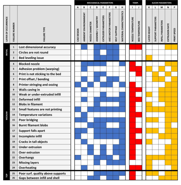
3D printing parameters allowing failure correction

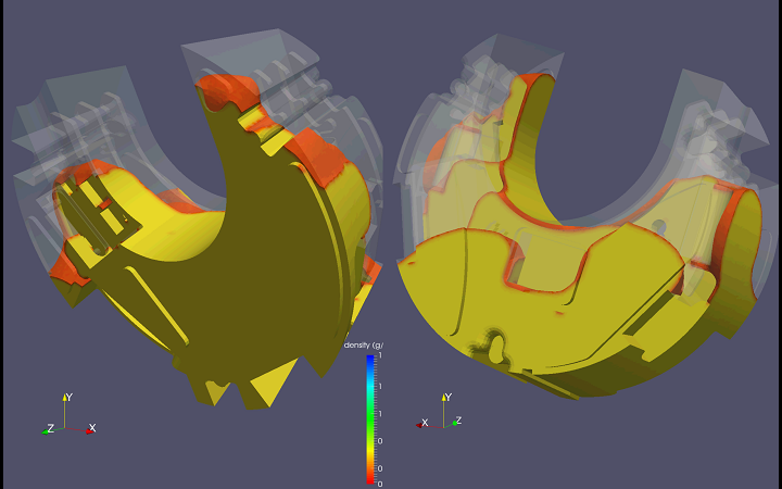
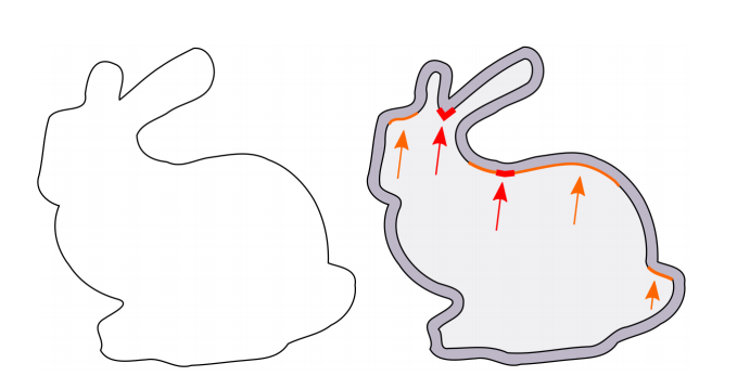
“The developed framework analyzes both global (deformation of overall dimensions) and local (deformation of filling) deviations of print modes, it restores the level of scale and displacement of the deformed layer and introduces a potential opportunity of repairing internal defects in printed layers,” explain Petsiuk and Pearce in their paper.

Parameters such as the following can be controlled:

  • Temperature
  • Feed rate
  • Extruder speed
  • Height of layers
  • Line thickness

While in most cases it may be impossible to compensate for mechanical or design errors, a suitable algorithm can cut down on the number of print failures significantly. In this study, the authors used a Michigan Tech Open Sustainability Technology (MOST) Delta RepRap FFF-based 3D printer for testing on a fixed surface improving synchronization between the printer and camera, based on a 1/2.9 inch Sony IMX322 CMOS Image Sensor and capturing 1280×720 pixel frames at a frequency of 30 Hz.

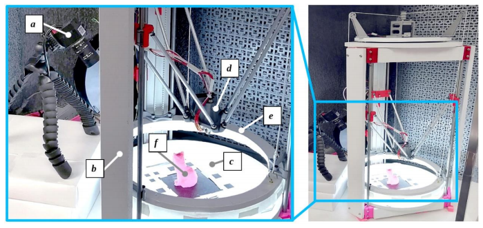
Visual Servoing Platform: working area (left), printer assembly (right): a – camera; b – 3-D printer frame; c – visual marker plate on top of the printing bed; d – extruder; e – movable lighting frame; f – printed part.

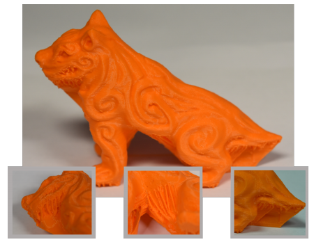
Projective transformation of the G-Code and STL model applied to the source image frame: a – camera position relative to the STL model; b– G-Code trajectories projected on the source image frame. This and the following slides illustrate the printing analysis for a low polygonal fox model [63].

The algorithm monitors for printing errors with the one camera situated at an angle, watching layers being printed—along with viewing the model from the side:

“Thus, one source frame can be divided into a virtual top view from above and a pseudo-view from the side.”

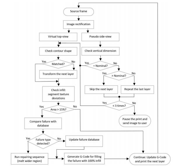
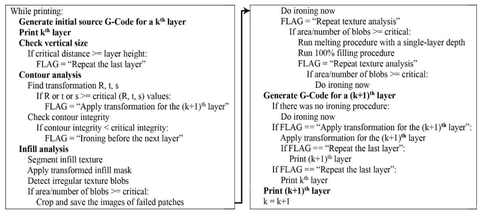
3D printing control algorithm

Currently, the study serves as a tool for optimizing efficiency in production via savings of time and material but should not be considered as a “full failure correction algorithm.”

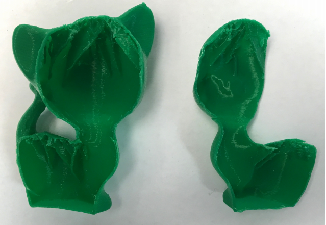
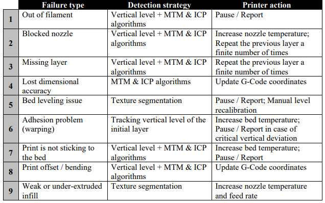
Example of failure correction

Interested in finding out more about how to use this open-source analysis program? Click here.

[Source / Images: “Open Source Computer Vision-based Layer-wise 3D Printing Analysis”]

The post Michigan Tech Develops Open Source Smart Vision for 3D Printing Quality Control appeared first on 3DPrint.com | The Voice of 3D Printing / Additive Manufacturing.

Julia Körner’s 3D-Printed Setae Jacket Inspired by Butterfly Wings

The delicate wings of a butterfly have inspired a great deal of 3D-printed innovations, such as stronger structures for electronics and ultra lightweight geometries for better load bending, unique artwork, and even fashion. Pioneering 3D-printed fashion designer, architect, adjunct professor at UCLA, and, most recently, 3D-printed costume designer, Julia Körner has long used the technology in her work. Now, she has turned to 3D printing once again for the design of her eye-catching Setae Jacket, which was, as you may have guessed, inspired by butterfly wings.

“Julia Koerner is an award-winning Austrian designer working at the convergence of architecture, product and fashion design. She is internationally recognised for design innovation in 3D-Printing, Julia’s work stands out at the top of these disciplines,” her website states. “The constantly intriguing aspect of Julia’s work is its embodiment of a beautiful organic aesthetic.”

She was one of 15 designers chosen by non-profit organization Austrianfashion.net to show her work—the 3D printed Setae jacket—at its recent Virtual Design Festival (VDF). The organization is a platform that is focused on promoting contemporary Austrian fashion designers and partnered with VDF to exhibit innovative fashion designs and accessories by designers who were either born, or are currently based, in Austria, and also produce their work locally and sustainably.

Austrianfashion.net said, “[Körner’s] work on the future of 3D, as well as on its current applications, can be seen as revolutionary practice. Strongly believing that the future of fashion is 3D, Körner is making sure she is at the forefront of the revolution.”

Her beautiful, 3D-printed Setae Jacket is part of the 3D printed Chro-Morpho fashion design collection by Stratasys, which we’ve discussed here before, and was also inspired by colorful butterfly wings. The collection is meant to show how technology and textiles can work together, and even create commercially viable pieces of clothing. The jacket was 3D printed out of flexible Vero material on one of the company’s multimaterial printers, either the J750 or the J850, and every bristle resembles setae, which is a stiff structure akin to a hair or a bristle.

“The research explores digital setae pattern design and multi-color 3D printing on fabric, inspired by microscopic butterfly wing patterns. Butterfly wings are made up of membranes which are covered by thousands of colorful scales and hairs, plate-like setae,” Körner’s website states.

She used photographs of Madagascan Sunset Butterfly wings, and the setae on the wings were actually digitized into an algorithm, “which translates the color pixels into 3D bristle patterns which correspond to the form of the garment design.”

“The digital designs are 3D printed in an innovative way, without any support material and directly on fabric,” the site continues. “The relation between the colourful rigid setae and the flexible fabric create enigmatic visual effects when the garment is in motion.”

To form the jacket, the bristles were 3D printed on denim. When the garment is worn, the setae move along with the person, which is a really interesting effect.

“Due to the movement and delicate color transformation, it expresses a true organic animal flow that comes to life,” Stratasys states.

Do I spy a zipper?

It is definitely a unique piece, and while lack of comfort and wearability is always one of my biggest critiques when it comes to 3D-printed fashion, the Setae Jacket absolutely looks wearable to me.

What do you think? Discuss this story and other 3D printing topics at 3DPrintBoard.com or share your thoughts in the comments below.

(Source: Dezeen / Image Credits: Ger Ger 2019)

The post Julia Körner’s 3D-Printed Setae Jacket Inspired by Butterfly Wings appeared first on 3DPrint.com | The Voice of 3D Printing / Additive Manufacturing.

Free Automated Software to Design 3D Printable Cranial Implants

Repairing skull defects with custom cranial implants, otherwise known as a cranioplasty, is expensive and takes a great deal of time, as the the existing process often results in bottlenecks due to long wait times for the implant to be designed, manufactured, and shipped. While 3D printing the implants can help with these issues, a team of researchers from the Graz University of Technology and Medical University of Graz in Austria published a paper, “An Online Platform for Automatic Skull Defect Restoration and Cranial Implant Design,” about an automated system for cranial implant design they’ve devised that can do even better.

“Due to the high requirements for cranial implant design, such as the professional experience required and the commercial software, cranioplasty can result in a costly operation for the health care system,” the researchers wrote. “On top, the current process is a cause of additional suffering for the patient, since a minimum of two surgical operations are involved: the craniotomy, during which the bony structure is removed, and the cranioplasty, during which the defect is restored using the designed implant. When the cranial implant is externally designed by a third-party manufacturer, this process can take several days [1], leaving the patient with an incomplete skull.”

In the case study they cited above, the researchers explained that a professional design center in the UK designed the cranial implant for a patient who lived in Spain. The CT scans had to be transferred from the hospital in Spain to the UK design center, and then a separate UK company 3D printed the titanium implant, which was shipped back to Spain. That’s a lot of unnecessary back and forth.

“Therefore, the optimization of the current workflow in cranioplasty remains an open problem, with implant design as primary bottleneck,” they stated.

“Illustration of In-Operation Room process for cranial implant design and manufacturing. Left: a possible workflow. Right: how the implant should fit with the skull defect in terms of defect boundary and bone thickness.”

One option is developing ad hoc free CAD software for cranial implant design, but the design process still requires expertise and an extended wait.

“In this study, we introduce a fast and fully automatic system for cranial implant design. The system is integrated in a freely accessible online platform,” the team explained. “Furthermore, we discuss how such a system, combined with AM, can be incorporated into the cranioplasty practice to substantially optimize the current clinical routine.”

The system they developed has been integrated in Studierfenster, an open, cloud-based medical image processing platform that, with the help of deep learning algorithms, automatically restores the missing part of a skull. The platform then generates the STL file for a patient-specific implant by subtracting the defective skull from the completed one, and it can be 3D printed on-site.

“Furthermore, thanks to the standard format, the user can thereafter load the model into another application for post-processing whenever necessary,” the researchers wrote. “Multiple additional features have been integrated into the platform since its first release, such as 3D face reconstruction from a 2D image, inpainting and restoration of aortic dissections (ADs) [4], automatic aortic landmark detection and automatic cranial implant design. Most of the algorithms behind these interactive features run on the server side and can be easily accessed by the client using a common browser interface. The server-side computations allow the use of the remote platform also on smaller devices with lower computational capabilities.”

3D printing the implants makes the process faster, and combining it with an automated implant design solutions speeds things up even more. The researchers explained how their optimized workflow could potentially go:

“After a portion of the skull is removed by a surgeon, the skull defect is reconstructed by a software given as input the post-operative head CT of the patient. The software generates the implant by taking the difference between the two skulls. Afterwards, the surface model of the implant is extracted and sent to the 3D printer in the operation room for 3D printing. The implant can therefore be manufactured in loco. The whole process of implant design and manufacturing is done fully automatically and in the operation room.”

The cost decreases, as no experts are required, and the wait time is also reduced, thanks to the automatic implant design software and on-site 3D printing. The patient’s suffering will also decrease, since the cranioplasty can be performed right after removal of the tumor.

“Architecture of automatic cranial implant design system in Studierfenster. The server side is responsible for implant generation and mesh rendering. The browser side is responsible for 3D model visualization and user interaction.”

The team’s algorithm, which processes volumes rather than a 3D mesh model, can directly process high dimensional imaging data, and is accessible to users, and easy to use, through Studierfenster. Another algorithm on the server side of the system converts the volumes of the defective, completed skull, and the implant into 3D surface mesh models. Once they’re rendered, the user can inspect the downloadable models in the browser window.

“An example of automatic skull defect restoration and implant design. First row: the defective skull, the completed skull and the implant. Second row: how the implant fits with the defective skull in term of defect boundary, bone thickness and shape. To differentiate, the implant uses a different color from the skull.”

“The system is currently intended for educational and research use only, but represents the trend of technological development in this field,” the researchers concluded. “As the system is integrated in the open platform Studierfenster, its performance is significantly dependent on the hardware/architecture of the platform. The conversion of the skull volume to a mesh can be slow, as the mesh is usually very dense (e.g., millions of points). This will be improved by introducing better hardware on the server side. Another limiting factor is the client/server based architecture of the platform. The large mesh has to be transferred from server side to browser side in order to be visualized, which can be slow, depending on the quality of the user’s internet connection.”

Discuss this and other 3D printing topics at 3DPrintBoard.com or share your thoughts below.

The post Free Automated Software to Design 3D Printable Cranial Implants appeared first on 3DPrint.com | The Voice of 3D Printing / Additive Manufacturing.

What is Metrology Part 15: Inverse Filtering

Signal Processing

Signal processing is the name of the game that must be played in order to do image processing. Image processing is such a fascinating subject that I am excited to expand upon it.  It has amazing cross sectionality within various fields such as metrology, 3D printing, biomedical industries, and any industry that uses imaging as its main technology. Today we will be taking a look into inverse filtering as a specific method within signal processing. Signal processing is a general domain of expertise that can be applied in different settings. For the purposes of where we are in our metrology series, we will only focus on image processing.

imagerestoration.gif

Inverse Filtering

Inverse filtering is a method from standard signal processing. For a filter g, an inverse filter h is one that where the sequence of applying g then h to a signal results in the original signal. Software or electronic inverse filters are often used to compensate for the effect of unwanted environmental filtering of signals. Within inverse filtering there is typically two methodologies or approaches taken: thresholding and iterative methods. The point of this method is to essentially correct an image through a two way filter method. Hypothetically if an image is perfect, there will be no visible difference. The filters applied will correct a majority of errors within an image.

When we know of or have the skill to create a good model for a blurring function of an image, it is best to use inverse filtering. This is because having a model, or let’s say algorithm, allows us to efficiently and succinctly apply mathematical constraints to data in an instantaneous manner. The inverse filter is typically a high pass filter. 

ECG high-pass filter

A high-pass filter (HPF) is an electronic filter that passes signals with a frequency higher than a certain cutoff frequency and attenuates signals with frequencies lower than the cutoff frequency. In physics, attenuation is the continuous loss of flux intensity through an object. Flux is a rate of flow through a surface or substance in physics. For instance, dark glasses attenuate sunlight, lead attenuates X-rays, and water and air attenuate both light and sound at variable attenuation rates. The amount of attenuation for each frequency depends on the filter design. A high-pass filter is usually modeled as a linear time-invariant system. It is sometimes called a low-cut filter or bass-cut filter. If the cutoff frequency is lower than the cutoff frequency, our image will not allow for certain features to be shown in the next image transformation. This efficient method is great for low frequency signals, but the world and image data is not low frequency.  The outputs from the world are typically noisy. The linear time-invariant system of a high pass filter is needed in order to constrain the outputs one receives from the universe. When time is added as a variable for a signal, wild things can happen in terms of frequency. In order to conduct an inverse filter we have two techniques: thresholding and the iterative procedure. 

Thresholding

The word threshold can be defined as a level, point, or value above which something is true or will take place and below which it is not or will not. Thresholding in image processing refers to setting a value limit on the pixel intensity of an image. This threshold can be thought of in terms of our earlier discussion on filters. The image processing method is able to create a binary image. This technique is usually applied to grayscale images, but it can be applied to color images as well. We are able to dictate the level of intensity that we want to have our transformed image at. Pixels that are below this value are converted to black – this is the value of zero in binary code. Pixels above the threshold value are then converted to white – this is the value of one in binary code. 

The iterative method within inverse filtering is more of a mathematical guess and check solution. The goal is to guess what the original image was in terms of image processing.  With each mathematical guess, a user is able to build a better fitting model to represent a digital image. This method is more of a brute force algorithm method. This method is not as efficient as the thresholding method, but it does have the advantage of better stability when dealing with noise. We do not need to be time invariant when dealing with this method. 

Overall, this is only one of the many examples of image processing techniques. As a follow up to this article, I will do some interactive code and I’ll showcase some of the power of these methods when we are taking a look at these problems through the lens of computer science and engineering.

The post What is Metrology Part 15: Inverse Filtering appeared first on 3DPrint.com | The Voice of 3D Printing / Additive Manufacturing.

3Dflow Computer Vision Software

3Dflow

3Dflow

3Dflow is a private software company operating in the field of Computer Vision and Image Processing. It was established in 2011 as a spin-off of the University of Verona, and in  2012 it became a spin-off of the University of Udine. 3Dflow is a company that provides solutions in Photogrammetry, 3D modeling of reality, 3D processing, and 3D visual effects. Their customers range from small industries competitors to large scale entertainment companies. In this article we will be analyzing this company as well as showcasing their workshop for 3D imaging and photogrammetry, as well as their world cup competition.

3Dflow is a company that is based in Italy. It is a small organization with fewer than 15 employees. The main value proposition this organization gives is its ability to use computer vision and software in combination to create 3D image data. For the stitching of the point cloud data of multiple photos, the organization provides software that does this for the user. The software is called 3DF Zephyr. 3DF Zephyr comes in the following forms:

  • 3DF Zephyr Free
  • 3DF Zephyr Lite
  • 3DF Zephyr Pro
  • 3DF Zephyr Aerial

Image result for 3d flow photogrammetry

3DF Zephyr Free

The free version of 3DF Zephyr includes full 3D construction, a 50 photo limit, single NVIDIA GPU support, basic exporting capabilities, and basic editing tools, and full forum support. 3DF Zephyr Lite differences include Dual NVIDIA GPU Support, 1 year upgrades included, basic email, and full forum support. The 3DF Zephyr Pro version has full exporting capabilities, advanced editing tools, control points & measurements, laser scan support, 1 year upgrades included, full email, and forum support. 3D Zephyr Aerial has all the previous abilities and GIS, CAD, and Survey Tools. 

3Dflow still comes from an educational background in terms of its founding story. It explains how they have transitioned to a consulting company as well as an organization that is focused on research and development. It also explains why they offer a free version of their software as an educational version for students. They care about building software for the future of photogrammetry as well as 3D imaging. They have developed specific algorithms and frameworks that are proprietary to their organization. This includes:

  • 3DF Samantha
  • 3DF Statsia
  • 3DF Sasha
  • 3DF Masquerade

3DF Stasia is the proprietary algorithm to extract very accurate dense point clouds from a set of 2D images. In Computer Vision this process is best known as a multiview stereo. The first step is to extract the corresponding points in two images and the second step is the 3D reconstruction with algorithms like Discrete Linear Transform. The Discrete Linear Transform, or Discrete Fourier Transform used in a linear model, converts a finite sequence of equally-spaced samples of a function into a same-length sequence of equally-spaced samples of the discrete-time Fourier transform (DTFT), which is a complex-valued function of frequency. The function we are dealing with in this case is the stitching together or images into 3D object data. Using DLT, the reconstruction is done only where there are SCPs. By increasing the number of points, the results improve but it is time consuming. This method has low accuracy because of low reproducibility and time consumption. This method is dependent on the skill of the operator. This method is not suitable for bony structures with continuous shape. This method is generally used as an initial solution for other methods. Hence the other technology developed by 3DF is vital. 

Mathematics of Discrete Fourier Transform

3DF Sasha is their proprietary algorithm for mesh extraction: given a dense point cloud full of details, it is important to preserve as much detail as possible when extracting the surface. Sasha allows one to get sharp edges on a 3D model and that is why it is more suitable for applications such as architecture, industrial surveying, and urban monitoring. Without the precision of point cloud data, the resulting stitch of 2D images would come out to be noisy. 

To clean up residual noise from the data, 3Dflow employs their 3DF Masquerade tool. This tool has been developed as an external executable that is included in the 3DF Zephyr installation package. Masquerade can mask images so it can save time during masking operations. 3DF Masquerade is helpful when there is a lot of background noise or when the subject has been moved incoherently with the background: the most common scenario is a subject that is being acquired on a turntable.

Image result for noisy 3D data

Example of a Noisy 3D mesh


The first photogrammetry & 3D scanning training course in the English language by 3Dflow in Verona (Italy), next September 30th, October 1st and October 2nd! One will learn photogrammetry with 3DF Zephyr: this course will tackle everything from photography for photogrammetry (basic and advanced shooting techniques) to data processing with 3DF Zephyr, on both photogrammetry-only workflows and a external-data oriented workflows (e.g. laser scanners). Theory and practice on the software will be paired with an actual test-acquisition Verona, a world-famous history-rich cities in Italy and home of 3Dflow. 

I will be attending this workshop to learn and report on this next month, but I encourage others to look into the 3Dflow organization and see what they are doing. Also be sure to signup for their workshop here.


The post 3Dflow Computer Vision Software appeared first on 3DPrint.com | The Voice of 3D Printing / Additive Manufacturing.

Simulation First Initiative Helps Honeywell Engineers Find Optimal Parameters for 3D Printed & Machined Parts

Honeywell FM&T, an engineering, manufacturing and sourcing enterprise that’s part of aerospace company Honeywell, manages and operates the Kansas City National Security Campus (KCNSC) for the US Department of Energy (DOE). In addition to providing technical services like metallurgy, analytical chemistry, and simulation tools, its mission is to make non-nuclear mechanical, electronic, and engineered material components for national defense systems. Honeywell and the KCNSC are collaborating with Sandia National Laboratories on a new initiative called Simulation First.

Sim First was launched by Honeywell engineers at the campus, and is helping them reduce costs, while driving manufacturing speed and productivity, at the same time – before they even reach the prototype stage.

“The effort uses physics-based tools to simulate production operations – all while in the concept phase,” Tanya Snyder, the Communications Manager for Honeywell and a Contractor for the KCNSC, told 3DPrint.com. “This reduces the number of tests required to find the right process and manufacturing parameters for 3D-printed and traditionally machined parts, resulting in less cost and production time.”

Kansas City National Security Campus [Image: DOE]

This strategic partnership marries Sandia’s code development skillset with the KCNSC’s use of simulation in critical and continuing production processes. In the past, the KCNSC has partnered with Sandia on 3D printing replacement parts for a nuclear warhead, and has also worked with Honeywell on tool design.

Before Honeywell’s ideas even leave the concept phase, the Sim First program uses tools and algorithms to figure out when and where materials could break, in addition to how well they will stand up under extreme temperatures and shock…obviously important when it comes to applications regarding the country’s national security. The program lets the engineers know if their parts are the right firmness, structure, and weight. Finally, calculations will optimize the final design and develop the optimal manufacturing parameters and processes for the product, whether they’re traditionally or additively manufactured parts.

Snyder provided us with a good example of how Sim First works that involves creating foam parts, which, because of their processing procedures and complicated chemical make-up, have always had low production yields in the past.

“Under SimFirst, the KCNSC and Sandia worked together to find a way to predict the expansion of Polyurethane foam in an enclosure,” Snyder explained.

“Sandia developers created a model that’s now been applied 400+ times at the KCNSC. The model predicts the fill behavior of every encapsulated component being developed for production. The end result has been the creation of fewer physical prototypes and a faster development schedule.”

In the above image, you can see an encapsulation fill simulation, which provides Honeywell engineers with the product’s “optimal density and fill levels,” all before they even start to work on the final prototype itself. Early access to this kind of data can really help lower the costs and time that are part of the life cycle of product development.

What do you think about this initiative? Discuss this story and other 3D printing topics at 3DPrintBoard.com or share your thoughts in the Facebook comments below. 

The post Simulation First Initiative Helps Honeywell Engineers Find Optimal Parameters for 3D Printed & Machined Parts appeared first on 3DPrint.com | The Voice of 3D Printing / Additive Manufacturing.

What is Metrology Part 8: Complex Analysis, Optics, and Metrology

The field of metrology is interesting for me as it integrates a lot of what I enjoy in physics and technology. The field from the outside seems very bland, but when you delve into the background, it becomes a more colorful picture. The field is reliant on the physics behind optics and image processing. These are areas of extreme interest to me. Visualization and capturing visualization data is essential for the field. A lot of this data is difficult to interact with as well because the data must be interpreted as a function that can be manipulated for reconstruction purposes from point cloud data. The mathematics behind this is what can be referred to a complex analysis. Today I will give some basic insight into these advanced concepts of physics and how they open us to learning more about metrology and 3D scanning. 

Let’s first talk about the field of optics. Optics is the branch of physics that studies the behaviour and properties of light, including its interactions with matter and the construction of instruments that use or detect it. Optics usually describes the behaviour of visible, ultraviolet, and infrared light. Because light is an electromagnetic wave, other forms of electromagnetic radiation such as X-rays, microwaves, and radio waves exhibit similar properties.

Optical science is studied in many related disciplines including astronomy, various engineering fields, photography, and medicine. Practical applications of optics are found in a variety of technologies and everyday objects, including mirrors, lenses, telescopes, microscopes, lasers, and fibre optics, as well as metrology practices.


Yes Imaginary Numbers are useful

I personally have a strong fascination with the field of optics. Firstly, I wear glasses and my glasses help me “see” more. The field of optics quickly takes a dive into metaphysical thought processes on human perception as well as what we actually see. Optics is the center of how most of us “see” the world. When we are in the field of metrology we are relying on man-made technology to measure what we see as humans. The realization that we as humans are measuring reality and physical dimensions is a bit mind-boggling. We do not necessarily know what reality is, but we use metrology to measure for us what is within our “grasp”.

Here is where it starts to become a bit more interesting. What defines the system we are in as humans who are measuring within their current state of reality? There must be a larger system that allows for this to occur. This is where complex analysis comes into play. Complex analysis, traditionally known as the theory of functions of a complex variable, is the branch of mathematical analysis that investigates functions of complex numbers. It is useful in many branches of mathematics, including algebraic geometry, number theory, analytic combinatorics, applied mathematics; as well as in physics. As a differentiable function of a complex variable is equal to the sum of its Taylor series (that is, it is analytic), complex analysis is particularly concerned with analytic functions of a complex variable (that is, holomorphic functions).

Complex Analysis 3D Function

For those of you intimidated by math, I will explain the meaning behind the math. Complex analysis is the branch of mathematics that is trying to understand the imaginary or complex plane of the universe we are confined to. We are working within 3 degrees of freedom or 3-dimensionality within our universe. The system of the universe is not determined by what is seen in the 3-dimensional world. Our perception is not what easily moves the universe. The forces that work on our 3-dimensional universe are applied through the fourth dimension or the complex plane of the universe. For all those who want to learn more physics be sure to enjoy immense philosophical implications. So why is all of this relevant to metrology and optics? Think about this. The signals or data we receive from viewing images is distorted by the complex realm. If it was not, there would be extremely high resolution images taken on a consistent basis. That tiny bit of blur in a photo, for example, is a byproduct of the complex world interacting with the physical realm we are within. This is what typically creates a noisy signal typically in physics. In signal processing, noise is a general term for unwanted (and, in general, unknown) modifications that a signal may suffer during capture, storage, transmission, processing, or conversion. Noise reduction, the recovery of the original signal from the noise-corrupted one, is a very common goal in the design of signal processing systems, especially filters. The mathematical limits for noise removal are set by information theory, namely the Nyquist–Shannon sampling theorem.

The data we are collecting, or information, is prone to noise. We live in the 3rd dimensions and the complex plane consistently is interacting with our signals or data. Thus we use filters to help with noise cancellation. This is the basis of image processing and digital image reconstruction. The algorithms being created currently for photogrammetric filters are extremely vital for the future of 3D reconstruction. These filters will rely heavily on the field of complex analysis to build better filters. Then we will have very clean 3D reconstructions from our metrology practices. For all those who are intrigued, I will continue to explain different items within the 3D metrology field.

The post What is Metrology Part 8: Complex Analysis, Optics, and Metrology appeared first on 3DPrint.com | The Voice of 3D Printing / Additive Manufacturing.

French Researchers Develop Algorithm to Generate Interior Ribbed Support Vaults for 3D Printed Hollow Objects

Hollowed Bunny printed with our method, using only 2.2% of material inside (compared to a filled model). The supports use 316 mm of filament over a total of 1,622 mm for the print).

In 3D printing, every layer of material must be supported by the layer below it in order to form a solid object; when it comes to FFF 3D printing, material can only be deposited at points that are already receiving support from below. French researchers Thibault Tricard, Frédéric Claux, and Sylvain Lefebvre, from the Université de Limoges (UNILIM) and the Université de Lorraine, wanted to look at 3D printing hollow objects, and proposed a new method for hollowing in their paper “Ribbed support vaults for 3D printing of hollowed objects.”

The abstract reads, “To reduce print time and material usage, especially in the context of prototyping, it is often desirable to fabricate hollow objects. This exacerbates the requirement of support between consecutive layers: standard hollowing produces surfaces in overhang that cannot be directly fabricated anymore. Therefore, these surfaces require internal support structures. These are similar to external supports for overhangs, with the key difference that internal supports remain invisible within the object after fabrication. A fundamental challenge is to generate structures that provide a dense support while using little material. In this paper, we propose a novel type of support inspired by rib structures. Our approach guarantees that any point in a layer is supported by a point below, within a given threshold distance. Despite providing strong guarantees for printability, our supports remain lightweight and reliable to print. We propose a greedy support generation algorithm that creates compact hierarchies of rib-like walls. The walls are progressively eroded away and straightened, eventually merging with the interior object walls.”

Figure 2: A Stanford bunny model is hollowed using a standard offsetting approach. The resulting cavity (R) will not print properly due to local minima (red) and overhanging areas (orange).

While most people think of 3D printing supports as external ones that support overhanging parts of an object, the interior of an object may also need support structures.

“Hollowing a part is not trivial with technologies such as FFF,” the researchers explained. “In particular, the inner cavity resulting from a standard hollowing operator will not be printable: it will contain regions in overhang (with a low slope, see Figure 2) as well as local minima: pointed features facing downwards. There is therefore a need for support structures that can operate inside a part.”

Inner supports should occupy a small amount of space with the print cavity, and the impact on overall print time should be slight. Other researchers have contributed a variety of ideas in terms of support structures with 3D printed hollowed objects, including:

  • sparse infills
  • self-supported cavities
  • external supports as internal structures

“We propose an algorithm to generate internal support structures that guarantee that deposited material is supported everywhere from below, are reliable to print, and require little extra material,” the researchers wrote. “This is achieved by generating hierarchical rib-like wall structures, that quickly erode away into the internal walls of the object.

“Our algorithm produces structures offering a very high support density, while using little extra material. In addition, our supports print reliably as they are composed of continuous, wall-like structures that suffer less from stability issues.”

Hollow kitten model printed with our method and split
in half vertically.

The researchers explained how to support a 3D object by “sweeping through its slices from top to bottom” and searching for any unsupported parts, then adding necessary material below them in the next slice; this material doesn’t need to cover the entire unsupported area, and can take any shape.

“The amount of material added can also be larger than the area needing support. Depositing more material than necessary comes at the price of longer printing times, but can be interesting to significantly improve printability,” the researchers explained. “Large, simple support structures often are faster to print than complex, smaller structures. Indeed, when multiple disconnected locations need to be supported, it is in many cases more effective to print a single, large structure. It encompasses and conservatively supports many small locations. This is more effective than supporting isolated spots, which individual support size may be very small and therefore difficult to print, and which will inevitably increase the amount of travel and therefore print time (taking nozzle acceleration and deceleration into account).”

The team then explained their algorithm for ribbed support vault structures. The idea is to use three main operations to produce supports: propagating and reducing supports from the above slice, detecting areas that appear to be unsupported in the current slice, and adding the supports needed for it.

“Our inspiration comes from architecture, where supports are generally designed in an arch (and vault) like manner. In particular, vaults tend to join walls in any interior space, with only a few straight pillars directed towards the floor. Similarly, many vault structures present hierarchical aspects. Such hierarchies afford for dense supports while quickly reducing to only a few elements – much like trees,” they wrote.

“Within each slice we favor supports having a rectilinear aspect: they provide support all around them while eroding quickly from their ends. Thus, within a given slice, we seek to produce rectilinear features covering the areas to be supported.

“We propose to rely on 2D trees joining the object inner boundaries. Through the propagation-reduction operator, the trees are quickly eroded away (from their branches). Taken together across slices, the trees produce self-supported walls that soon join and merge with the object inner contours, much like the ribs of ribbed vaults.”

The team 3D printed a variety of PLA models with the same perimeters on different systems. Orange models were fabricated on an Ultimaker 3, while the yellow Moai was printed on an Ultimaker 2 and the octopus on a CR-10. A Prima P120 was used to make white models, the blue Buddha was printed on an eMotion Tech MicroDelta Rework, and a dual-color fawn was made on a Flashforge Creator Pro.

Demon dog printed using our method for external support.

The quality of these prints matches models with a dense infill, thanks to the full support property offered, and the algorithm generates multiple small segments that require individual printing, which led to many “retract/prime operations surrounding travels.”

“Depending on the printer model used, the quality of the extrusion mechanics, the user-adjustable pressure of the dented extrusion wheel on the filament, as well as the brand of the filament itself, a small amount of under-extrusion may happen,” the team explained.

“To compensate for this, we perform a 5% prime surplus at the beginning of each support segment: if the filament was retracted by 3 mm before travel, we push it back by 3.15 mm after travel. Because the extra prime may create a bulge, we avoid doing it when located too close to perimeters, so as to not impact surface quality.”

The team also evaluated how much material their method needed, and compared this with materials used for iterative carving and support-free hollowing methods. They also noted how layer thickness impacted support size, and recorded processing times.

Comparison with Support-Free Hollowing and Iterative Carving. The input volume represents the volume (in mm3) and height (in mm) of the model.

“While producing supports of small length, our algorithm is clearly not optimal. This is revealed for instance on low-angle overhangs,” the team wrote. “The inefficiency is due to the local choice of connecting support walls to the closest internal surface, ignoring the material quantity that will have to appear in slices below. While a more global scheme could be devised, it could quickly become prohibitively expensive to compute.”

The researchers concluded that their algorithm ensures complete support of deposited material, which can be helpful for extruding viscous or heavy materials like concrete and clay. They believe that their method for 3D printing hollowed objects through generating ribbed internal support structures could one day lead to novel external support structures as well.

Discuss this and other 3D printing topics at 3DPrintBoard.com or share your thoughts below.

Nervous System Works with Rice University Researchers 3D Printing Vascular Networks

Nervous System has been heavily engaged in experimenting with 3D and 4D printing of textiles in the past years, and all their research is paying off now as they find themselves engaged in the realm of tissue engineering. The Somerville, MA company is known for their generative design process, combining both programming and art within most of their serious projects, drawing bioengineers from Rice University to turn to them for added expertise.

Assistant professor Jordan Miller invited the Nervous System team to join his researchers on an incredible journey to fabricate examples of possible vascular networks via bioprinting—harnessing their knowledge of software and materials to find a way to create soft hydrogels. Kind of not a phantom but more a path towards ideas that can lead to concepts that may let us build true vascularized structures at one point. As Miller explains, in their research they were able to create large tissue blocks easily, but as so many scientists engaged in bioprinting today have discovered before them, it is extremely challenging to keep cells alive. Viability becomes the goal, and as that becomes more comprehensively mastered overall in bioprinting, it may finally unlock the door to true fabrication of organs that can be transplanted into the human body.

Open-source technology, mainly centered around 3D printing has offered huge opportunity for the bioengineers from Rice University to make progress in their work—and that was what drew them to Nervous System in the first place. Jordan became ‘captivated’ with the structures they were creating, specifically in their Growing Objects series, which was featured as an exhibit at the Simons Center for Geometry and Physics in Stonybrook, NY in August and September of 2014. In speaking with Nervous System, his proposal involved what they describe as an ‘epic task,’ to create simulated synthetic tissue and human organs.

Rendering showing lung-mimicking structures generated within different volumes

“The idea of taking our generative systems which are inspired by nature and using them to actually make living things was a dream come true,” states the Nervous System team in their case study.

Elsewhere the research did,

“…show that natural and synthetic food dyes can be used as photoabsorbers that enable stereolithographic production of hydrogels containing intricate and functional vascular architectures. Using this approach, they demonstrate functional vascular topologies for studies of fluid mixers, valves, intervascular transport, nutrient delivery, and host engraftment.”

As Miller and his expanding team continued to work on developing the necessary tools for bioengineering, part of their research resulted in a new 3D printing workflow called SLATE (stereolithography apparatus for tissue engineering). Their proprietary hardware can bioprint cells encased in soft gels that act just like vascular networks. Nervous System accompanied them (going back as far as 2016) in this bioprinting evolution by designing the materials for the networks—but with their background in programming, the contribution went far beyond designed materials and included customized software for creating ‘entangled vessel networks.’ These networks can be connected to both inlets and outlets for oxygen and blood flow, as they use specific algorithms to ‘grow’ the branching airways.

“Air is pumped into the network and it pools at the bulbous air sacs which crown each tip of the network,” states Nervous System in their case study. “These sacs are rhythmically inflated and deflated by breathing action, so called tidal ventilation because the air flow in human lungs is reminiscent of the flows of the ocean tides.

“Next we grow dual networks of blood vessels that entwine around the airway. One to bring deoxygenated blood in, the other to carry oxygen-loaded blood away. The two networks join at the tips of the airway in a fine mesh of blood vessels which ensheathes the bulbous air sacs. These vessels are only 300 microns wide!”

This project, bringing together scientists and art designers, was featured in the American Association for the Advancement of Science (AAAS) in ‘Multivascular networks and functional intravascular topologies within biocompatible hydrogels,’ authored by Bagrat Grigoryan, Samantha J. Paulsen, Daniel C. Corbett, Daniel W. Sazer, Chelsea L. Fortin, and Alexander J. Zaita.

The recently published article goes into great detail about SLATE 3D printing, indicating that this hardware is capable of rapid bioprinting, and offering possible sustainability to human cells—along with maintaining functionality of stem cells and necessary differentiation.

The project was created by Jordan Miller at Rice University and Kelly Stevens at the University of Washington, and included 13 additional collaborators from Rice, University of Washington, Duke University, and Rowan University.

Nervous System is undeniably one of the most fascinating companies producing 3D printed innovations today. Their versatility has led them to create everything from 4D textiles and 3D printed stretched fabrics to their famed Kinematics Petal Dress. With their latest project delving into 3D printed tissue, the stakes become higher—and their impact on the world much greater. Find out more here.

What do you think of this news? Let us know your thoughts! Join the discussion of this and other 3D printing topics at 3DPrintBoard.com.

The Miller Lab fabricated and tested the architectures we generated showing that they can withstand more than 10,000 ventilation cycles while being perfused with human red blood cells. Study of the printed gels shows that the architecture we designed promotes red blood cells mixing and bidirectional flow which is hypothesized to occur in the human lung.

[Source / Images: Nervous System]

Researchers Create Fuzzy Like PI Controller to Control FFF 3D Printer Extruder and Bed Heaters

Not this kind of fuzzy…
[Image: Utrecht University]

I learn all kinds of interesting things writing about 3D printing every day. Much to my chagrin, today I learned that a fuzzy print controller is not actually fuzzy or furry. For those of you who are also in the dark, fuzzy control systems are based on what’s called fuzzy logic: a mathematical system, introduced in 1965, where the truth values of variables could be any real number between 0 and 1 inclusive. It handles the concept of partial truth, where the truth value could be anywhere between totally true and completely false. The opposite is Boolean logic, which sets the truth values of variables as only true and false, or respectively, 1 and 0.

A trio of researchers from the Arab Academy for Science, Technology and Maritime Transport and the Electronics Research Institute in Egypt used fuzzy logic for a new study, titled “Fuzzy Controller Algorithm for 3D Printer Heaters,” about creating an easily tunable, closed-loop controller to run the heaters in an FFF 3D printer, which require its heaters to operate within temperature ranges that are well-suited for the specific material being printed.

The abstract of the study reads, “PID controllers are the most widely used. To efficiently design this controller, parameter-tuning must be done which is a time-consuming process. To save time, tuning could be performed by simulation, but this requires the system’s model. Some system models are difficult to deduce, thus other controllers that are independent of the system model and do not require multiple tuning iterations are used. An example of such controllers is the fuzzy like PI controller. This paper presents the design and implementation of a fuzzy like PI controller. The results for testing the controller are presented.”

System block diagram of fuzzy like PI controller

Heated beds can prevent warping and increase print quality, so it’s important to be able to control them properly. The team designed and implemented a model-free fuzzy like PI controller for the study, as it can capably control a non-LTI system with an unknown model. An FFF 3D printer with a heated bed and an extruder that can feed 1.75 mm filament was used, so the researchers could try to control the temperatures of both the bed and the extruder heater with the controller.

“To conduct this study, a 40-watt cartridge heater was used for the extruder and a 90-watt heater for the heat bed,” the researchers wrote. “Both heaters’ parameters were unavailable which made building their models difficult. The heat bed’s heater takes about 10 minutes to reach 100°C. Thus, system identification techniques are time consuming. Without the system model and with the time taken for the heat bed’s heater to reach the set point temperature, tuning a PID controller can be time-consuming. The heaters’ parameters could also be time-variant or have a dependency on other variables.”

They implemented the fuzzy like PI controller on an Arduino Nano board with a microcontroller that runs at 16 MHZ clock speed and has 32 KB of flash memory. A 12V 40W cartridge heater inserted in the heating block of the extruder assembly serves as the extruder heater, and the MK3 aluminum heat bed operates at 19 V; both can be seen in the figures below and are controlled by, as the researchers wrote, “varying the duty cycle of a PWM control signal produced by the microcontroller.”

The team tested the controller with both the heat bed and extruder heater, then used an Arduino serial monitor to send the data from the microcontroller to the computer. They determined that their fuzzy like controller displayed “adequate performance” while controlling the two heaters. With only minimal tuning and no need to perform system identification, steady state errors in the heat bed were as low as 0.95%, and 12.15% (due to lack of sensor sensitivity) in the extruder heater.

“The controller was suitable to be used on small microcontrollers as it occupied 7.5 Kb of Flash memory and 0.3 Kb of RAM, which leaves room to use other complex applications on the microcontroller,” the team concluded. “Therefore, the use of fuzzy like PI controller is highly justified.”

To learn more about the mathematics and logic behind the team’s fuzzy like PI controller, because I can absolutely not explain them to you, check out the research paper. Co-authors are A. E. El-Fakharany, M. R. Atia, and Mohamed I. Abu El-Sebah.

Discuss this research and other 3D printing topics at 3DPrintBoard.com or share your thoughts in the Facebook comments below.