
Stratasys has launched its new J55 3D printer. Aimed at professional designers and engineers, the PolyJet system looks to produce in-house ‘enterprise-quality’ prototypes at a third of the price of industrial-grade competitors. According to Stratasys, the J55 is a smaller but equally capable counterpart to the company’s established J8 series of PolyJet machines. Full-color capabilities […]
FDM 3D Printing & PLA: Fabrication of a Splint for Mallet Finger
Researchers from Australia and the UK are finding ways to improve treatments for injuries to the hand, detailing their results in the recently published ‘Patient-specific 3D-printed Splint for Mallet Finger Injury.’ The goal is to offer better outcomes for patients who may have experienced damage to the tendon responsible for straightening the joint found at the end of the finger (or thumb).
Mallet finger injuries most commonly occur due to trauma after being struck by an object that bends the finger or thumb tip painfully.
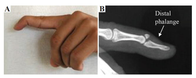
(A) Mallet finger fracture (Image courtesy from Sachin J Shah, MD, online), (B) anatomy of finger
While there are many injuries and illnesses far more seriously affecting lives today, losing the use of a finger or hand can be debilitating as we must use them for so many tasks—primarily at work. Many types of splints may be uncomfortable for the patient to wear, but are also labor-intensive and expensive to make, resulting in the use of excess material during production too.
3D printing and additive manufacturing processes are beginning to make an impact in manufacturing of orthotics, offering benefits like greater affordability, speed in production, and best of all—total customization. Innovation around the globe has resulted in new software and improved workflow for creating medical devices like orthotics, the production of more comfortable foot/ankle orthotics, myoletric orthotics, and more.
“Mallet finger is often left untreated by patients unless severe restriction in extensor ability is present, or there is lingering pain. This injury, in the case, that there are functional shortfalls, can impede the whole hand in everyday fine motor skill tasks,” explained the authors. “Furthermore, this deformity can develop additional medical conditions in the finger and hand as overcompensation can create hyperextension of proximal interphalangeal joint, a swan neck deformity.”
“Effective use of AM may lead to a reduction in size and weight of the splint making it more comfortable for the user.”
Today, the most common splints are the prefabricated stack splint, the dorsal aluminum splint, and the customized thermoplastic splint. Generally they are worn for six to eight weeks, but with the first two choices there may be ongoing comfort issues as the splints may not fit well causing the skin to become irritated, the patient may experience added pain, and the splint itself may break due to inferior materials or manufacturing. Many patients are also unhappy with the size and style of their splints.
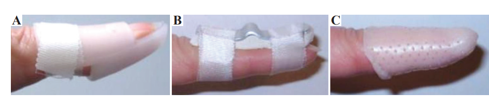
(A) Stack, (B) dorsal aluminum, and (C) personalized thermoplastic splints
“… customized splints, fitted to the exact dimensions of a patient’s finger, have the ability to provide successful treatment in more cases than the other two splint types,” stated the authors.
FDM 3D printing was chosen for the course of this study as the researchers made samples, noting that they would be taking advantage of the ability to fabricate complex geometries not previously possible through conventional techniques in manufacturing. More importantly is the ability to offer patient-specific treatment like never before—especially with medical devices like prosthetics and orthotics. In this study, the issue of comfort could be addressed with comprehensive customization, splints made quickly, and revised simply by changing the 3D design and printing a new one in the case of growth (these issues are common with children who may outgrow an orthotic made with conventional methods before it even arrives to them!), damage, or other requirements.
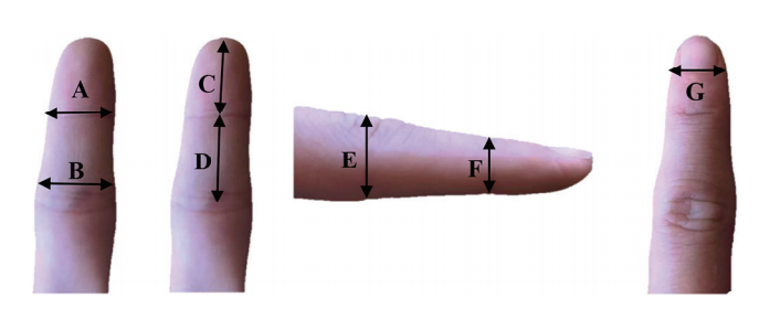
The seven measurements required to create a personalized finger splint computer-aided drawing model.
The research team used Autodesk Inventor for entering the measurements for their sample, including a built-in constraint:
“When the user clenches their fist, without this material removed, the skin of their middle phalanx finger can push into the back of the splint dislodging its correct position. The stack splint is designed with an open ventilation section above the fingernail to allow some airflow to reduce sweat when being worn and to allow limited access for washing.”
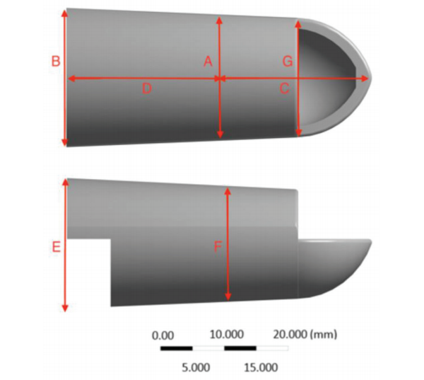
Geometry of a sample 100% mass design according to a patient’s finger.
Addressing the issue of wasted material and recycling of products later, the researchers point out that patient-specific devices like the splints they designed cannot be re-used by another individual later due to the level of customization, so they must be disposed of; however, with the use of PLA as their 3D printing material, a discarded splint can be ‘composted’ within six to eight weeks.
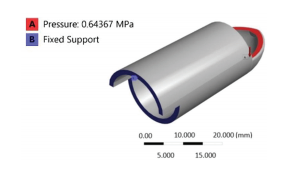
Schematic view of boundary conditions on a sample splint design.
One of the main objectives in the study was to develop a highly functional orthotic with topology optimization, eliminating as much material as possible while still maintaining the splint’s required volume fraction and stiffness.
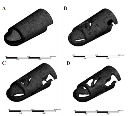
Domains discretization with tetrahedral elements for (A) 100%, (B) 79.49%, (C) 71.13%, and (D) 62.51% mass
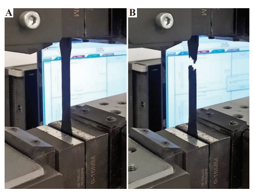
A three-dimensional-printed dog-bone poly-lactic-acid sample (A) before, and (B) after tensile test.
An Ultimaker2 Extended+ 3D printer was used for fabrication, while tensile testing was performed on an Instron 300LX.
“In FDM topology optimized and original design, finger splints were fabricated, original (100% mass), 62.51% mass, 71.13% mass, and 79.49% mass, by the same 3D printer and processing parameters used for the dog-bone specimens,” stated the researchers.
Noting that deflection results did not correlate exactly with heat dissipation, a trade-off analysis was required in choosing the best splint since the initial splint operating at 100 percent mass offered the best mechanical performance, but the 71.13 percent mass splint performed optimally in heat dissipation.

From left to right 62.51%, 71.13%, 79.49%, and 100% mass splints
“This splint is simpler to print than lower percentage mass splints that can require more printing support structures. It was found that inevitably reducing the amount of material in a load-bearing finger splint would increase the deflection of it. However, when the distribution of that material is chosen to optimize the stiffness in that situation, the deflection value was low enough to justify its use,” concluded the researchers.
“The results of this project would pave the way for the medical industry to utilize superior advanced manufacturing and minimum materials that have been shape optimized to better serve their purpose while improving patient comfort.”
What do you think of this news? Let us know your thoughts! Join the discussion of this and other 3D printing topics at 3DPrintBoard.com.
[Source / Images: ‘Patient-specific 3D-printed Splint for Mallet Finger Injury’]
The post FDM 3D Printing & PLA: Fabrication of a Splint for Mallet Finger appeared first on 3DPrint.com | The Voice of 3D Printing / Additive Manufacturing.
South Africa: FEA & Compression Testing of 3D Printed Models
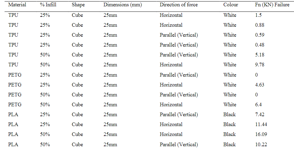
Researchers D.W. Abbot, D.V.V. Kallon, C. Anghel, and P. Dube delve into complex analysis and testing in the ‘Finite Element Analysis of 3D Printed Model via Compression Tests.’ For this study, the researchers used an FEA tool for simulation and testing of 3D printed parts, with a central focus on experimenting with ‘specific imposed conditions’ on the sample models—employing a strategy that allows for much faster, more affordable assessment of parts.
FEA allows researchers (and ultimately, manufacturers) to prove a variety of different prototypes created through other methods—but now a serious focus is being placed on parts printed in numerous different materials, to include ABS, PLA, and more. Square block samples were chosen for the study due to the potential for better accuracy and distribution of stress along surfaces—with the goal of allowing engineers to finally ‘trust’ FEM in terms of 3D printed objects.

Properties of some 3D printing materials.
Compression testing involved labeling 3D printed samples as either isotropic or anisotropic, with a focus on avoiding anisotropy and inter-layer voids. In examining the samples, the researchers were able to see the internal structures of FDM 3D printed parts, along with evaluating densities. Both experimental and computational tests were performed.
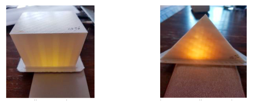
(left) 15% quality prototype in ABS (right) 85% quality prototype in ABS
“Results obtained using Autodesk Inventor are compared to the experimental test results. The arrow represents the direction in which the load has been applied to that of the axes experiencing the load. The horizontal axes, the original axis that the objects are printed on, representing an axially distributed load from above, against the grain of the layers, the vertical axis represents an axial load that would be experienced from the side of the test specimen, with the grain of the layers.”
FEA is centered around both the materials and techniques used, along with design—and the researchers point out that this could be different depending on the simulation software used. Both porosity and adhesion are both issues too. The researchers continued to note the ‘large discrepancy’ also between both experimental and simulated results, with test pieces exhibiting 50 percent more solidity than the experimental samples.

(left) before applied load (right) after applied load
On noting that samples ‘behaved poorly’ regarding horizontal/perpendicular loads, the researchers realized the 3D printed block samples were anisotropic. Infill simulated results and experimental results differed greatly too, as the Autodesk design and simulation were viewed as a solid (instead of porous) object; in fact, in some cases, the samples were not similar at all.
Practical test results
In observing samples (or functional parts), it is critical to evaluate:
- Area of application
- Environment of use
- Operational associated stress at specific axis
“The results obtained from this study on different materials at different applied loads across the two different layering axes showed a large variation in compressive strength,” concluded the researchers. “This establishes that the design of 3D parts strongly depends on the application of the part.”
While 3D printing offers a wide range of benefits, the ability to edit designs and create one iteration after another at will is one of the greatest draws in comparison to more conventional methods of production. Researchers today are engaged in many different types of feasibility studies, ways to introduce new workflow features and learn more about cost analyses.
What do you think of this news? Let us know your thoughts! Join the discussion of this and other 3D printing topics at 3DPrintBoard.com.
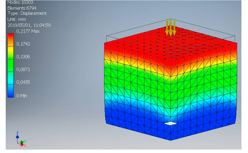
Maximum displacement at 12200N for ABS Plastic using Autodesk Inventor
[Source/Images: ‘Finite Element Analysis of 3D Printed Model via Compression Tests’]
The post South Africa: FEA & Compression Testing of 3D Printed Models appeared first on 3DPrint.com | The Voice of 3D Printing / Additive Manufacturing.
On-demand manufacturing service Xometry raises $50 million in equity funding
Xometry, a Maryland-based on-demand manufacturing and 3D printing service, has raised $50 million in equity funding. The funding round was led by Greenspring Associates, a venture capital firm in Maryland. Randy Altschuler, co-founder and CEO of Xometry, said, “We’re planning to invest these funds behind growth initiatives, product development and global expansion.” “Xometry’s vast network, massive […]
SOLIDWORKS 2019 workshop by Solid Solutions, a three hour introduction
SOLIDWORKS is among the most popular and widely used professional CAD/CAE software, primarily for product designing and engineering applications. Next week 3D Printing Industry will be reporting from the annual SOLIDWORKS World conference, ahead of this we take a look at some of features found in the software and a little of the history behind […]