3D Printing News Briefs: January 16, 2020

In today’s 3D Printing News Briefs, we’ve got a little business news, followed by stories about materials, and finally ending with some 3D printed fashion. PostProcess Technologies is expanding in Japan with a new partnership. Smart International has launched a material partnership program, and CRP Technology is introducing a new Windform material. Finally, a Spanish fashion brand is using BCN3D’s technology to make some of its clothing.

PostProcess Technologies Enters Asian Market with New Partnership

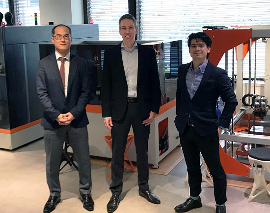
Executives from PostProcess and K.K. IRISU (C. ILLIES & CO., LTD.)

Automated post-printing solutions provider PostProcess Technologies Inc. announced that it’s entering the Asian additive manufacturing market, and expanding the reach of its solutions, by naming K.K. IRISU (C. ILLIES & CO., LTD.) as its first distribution partner in Japan. PostProcess chose the high-quality industrial machinery and technologies specialist, to help serve its growing base of customers in Japan and represent its data-driven technologies because of its expertise and experience. The partnership is mutually beneficial, as ILLIES can now offer its customers access to technology that will automate common post-printing processes and enable “additive manufacturing at scale.”

“K.K.IRISU’s main objective is to educate the Japanese market in additive manufacturing and to continue to be the solution provider for the Japanese 3D manufacturing world. We feel that by adding PostProcess Technologies to our lineup, will help assist the Japanese market to compete with other countries in Additive Manufacturing as well as globally maintain the high standards of the tag ‘Made in Japan’,” said Dr. Frank Oberndorff, President of K. K. IRISU.

Next month, both companies will exhibit at the Design Engineering & Manufacturing Solutions (DMS) 2020 Expo.

Smart International Introduces Material Partnership Program

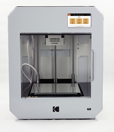
This week, Smart International, the global brand licensee in 3D printing for KODAK, announced the launch of a new Materials Partnership Program in order to help its customers achieve a repeatable 3D printing experience, while also meeting the demand for high-quality, yet easy-to-print, engineering materials. The company has already developed, and tested, material profiles for filaments from its partners BASF, Clariant, and DSM, which will help provide optimal conditions for these third party materials on the Portrait 3D printer. Print profiles were created from this data, and can either be accessed from the KODAK 3D Cloud or downloaded from the Smart3D website.

“We feel it is of vital importance to continually adapt to the ever-evolving 3D printing market. Partnering with top filament companies like BASF, Clariant and DSM gives the customer the opportunity to choose the material that best fits their project, and gives them confidence to use these high-quality 3rd party materials with the KODAK Portrait 3D Printer,” said Roberto Gawianski, the CEO of Smart International. “We are pleased to be able to assist in the development and evolution of 3D printing filaments, and will continue to support progress in this area.”

BASF material profiles include Ultrafuse ABS Fusion+, Ultrafuse PAHT CF15, Ultrafuse PA, and Ultrafuse Z PCTG, while Clariant now has a profile for its popular 20% carbon fiber-reinforced polyamide 6/66 PA6/66-CF20 filament. Smart International also created material profiles for DSM’s Novamid ID1030, Novamid ID1030 CF10, a carbon fiber filled PA6/66 copolymer filament and Arnitel ID2060 HT.

CRP Technology’s New Windform P2 Material

Italian company CRP Technology is introducing the latest material from its Windform P-LINE range – the glass fiber-reinforced thermoplastic polyamide Windform P2, which the company states has “excellent mechanical properties” for its High Speed Sintering (HSS) technology. The new material has high tensile strength (39.24 MPa), combined with increased stiffness (2925.20 MPa), and is great for insulating, as it is glass fiber-filled. Windform P2 is good for producing end-use parts that need high stiffness, as well as manufacturing components with detailed resolution.

“Windform® P2 is the second polymer from P-LINE, the new Windform® range of materials for high speed production-grade 3D printing, introduced on the market less than a year ago,” said Engineer Franco Cevolini, CRP Technology CTO and VP.

“This is a very important property. Windform® P2 is stiffer than Windform® P1 because Windform® P2 is reinforced (Windform® P1 is not reinforced). Most of the reinforced materials for similar technologies currently on the market, show a decrease in the tensile strength property. My staff and I have been able to preserve the high tensile strength in Windform® P2. Therefore, Windform® P2 overall’s performance is superior than the performance of similar materials currently on the market for similar technologies.”

ZER Collection 3D Printing Clothes with BCN3D

The 3D printed parts are made in TPU due to the flexibility of this material.

Spanish fashion brand ZER Collection introduced its first collection at the most recent Mercedes Benz Fashion Week in Madrid. The label, which was founded in 2017 by Núria Costa and Ane Castro and designs ‘futuristic, functional and urban clothing with sporty aesthetics,’ incorporated 3D printed parts, made with BCN3D’s Sigma printer, into 12 of the outfits; this system allows for the printing of two different materials, including flexible TPU. ZER Collection is using 3D printing in order to accelerate its production manufacturing processes and reduce waste, while also contributing to the use of sustainable new technologies in the apparel industry.

“We work much faster, because we can print two fabrics at the same time,” Costa said when explaining some of the benefits of using 3D printing to make their clothing, including their ability to “digitize all patterns in order to produce only the necessary fabric.”

“We believe that the use of 3D printing represents a revolution in fashion, in environmental care and in society.”

Discuss these stories and other 3D printing topics at 3DPrintBoard.com or share your thoughts in the Facebook comments below.

The post 3D Printing News Briefs: January 16, 2020 appeared first on 3DPrint.com | The Voice of 3D Printing / Additive Manufacturing.

3D Printed Cellular Fingers Offer Material Balance Required for Modern Robotics

In ‘Toward a Smart Compliant Robotic Gripper Equipped with 3D-Designed Cellular Fingers,’ authors Manpreet Kaur and Woo Soo Kim delve into the world of combining 3D printing and robotics. Their recently published paper focuses on the design of a robotic structure with deformable cellular structures that are easy to fabricate.

The conventional metal robot or robotic components are increasingly being upstaged by softer materials that offer more versatility for industrial applications. Not only that, many of these new materials are able to morph to their environment, affected by environments such as temperature or moisture. Kaur and Kim remind us that many of these innovations are originally inspired by nature, such as the movement of and the frictional properties of the snake.

Design and fabrication of multi‐material auxetic structure: A) 2D sketch of the re‐entrant honeycomb unit cell with defined parameters. B) Schematic demonstration of filament extrusion–based multi‐material 3D printing. C) Different designs of auxetic unit cells with two important parameters, α (the ratio of length of vertical strut h by re‐entrant strut l) and θ (the re‐entrant angle), defined in the sketch (A). D) The CAD image of the 3D re‐entrant honeycomb structure made by joining two 2D structures at 90°. The single tone gray color indicates the usage of a single material that is a TPU‐based flexible material. E) A dual‐material‐based auxetic unit cell where the re‐entrant struts (red) made of flexible material and the vertical struts (gray) made of rigid material. F) Different designs of dual‐material‐based auxetic unit cell, where the joints (gray) are made of flexible material and the rest of the portion of the struts (blue) are printed with the combination of both flexible and rigid material with equal proportion.

In creating soft robotics, however, there is the challenge of finding a balance between flexibility and structural stiffness and incorporating electronics which usually consist of a variety of different bulky systems. The cellular finger noted in this research can be made with embedded sensors in the fingertips, allowing for a significant gripping force of 16N, and the ability to pick up numerous objects—and acting as an example of more complex architectures for better functionality and performance overall.

“Stretching‐dominated cellular solids, such as octet, octahedral, and so on, show higher initial yield strength compared with bending‐dominated foamed materials, which is due to their different layout of structural components and makes them better alternatives for lightweight structural applications. One such unique spatially arranged structure produces a negative Poisson’s ratio (NPR); these are called auxetics. Like other types of mechanical metamaterials, the NPR of auxetics is generally a direct consequence of the topology, where the joints rotate to move the structure,” state the researchers.

Characterization of 3D printed auxetic structures: A) Compressed samples from the design with α = 1.5 and θ = −20°. Three different material distributions in the unit cell (single, dual 1, and dual 2 designs) are studied. Images were captured for each sample at 0%, 20%, and 40% strains. B) Stress–strain graph of three samples with different combinations of α = 1.5, 2 and θ = −20°, −30 ° for designs (single, dual 1, and dual 2). The legends read as “a” for alpha, “t” for theta, and S, D1, D2 for single, dual 1, and dual 2, respectively. C) Finite element analysis (FEA) simulation analysis of compressed auxetic unit cell to study the different stress distributions in the elastic region for the three different designs. The color code is kept constant and is defined next to each image. The corresponding elastic curves from experiment and simulation are compared for each case. D) The cellular finger is designed using the rigid stretching‐dominated octet structure for the main body and using chosen auxetic structure (α = 1.5 and θ = −20°) with dual 2 designs for the joints.

NPR materials are also able to deform and show ‘compliant-bending behavior.’ In this research project, Kaur and Kim used honeycomb structures—again, inspired by nature—examining their ability to absorb energy and bend. These re-entrant structures are more easily translated to the 3D realm and allowed the authors to experiment regarding parameters and resulting cell properties. The end goal was to achieve deformity, along with suitable durability and energy efficiency.

With the use of porous cellular materials meant to meet the balance of both softness and flexibility and the need for firmness also, the researchers were able to roll their knowledge of materials, manufacturing, and robotics into one—along with 3D printing and the use of triple materials. The robotic gripper finger was made up of the following lightweight parts:

  • Three octet segments
  • Two auxetic joints (mimicking human bones and joints)
  • Integrated pressure sensor on the fingertip

The following materials were used for 3D printing the single, dual 1, and dual 2 designs: SemiFlex, PLA, and carbon fiber reinforced PLA (CFRPLA). The porosity level allowed for the sought-after balance in a lightweight structure as well as offering the proper rigidity for various gripping functions. The overall design was also responsible for the system of fingers able to deform as needed, in tune with objects and their specific shapes—while the fingertip sensors monitoring the environment.

Mechanical properties of the samples from compression test

“Our architectured robotic finger is a starting point of cellular design concept. Therefore, there is a lot of room for further research in this topic. Design of other mechanical metamaterials has lots of opportunities, so other lattice structures can be investigated to tune additional mechanical deformation functionality in the robotic finger,” concluded the researchers.

“The optimization of sensor design and addition of other sensors can also be investigated to achieve its ubiquitous performance. This compliant robotic design with metamaterial body can prove to enhance the functionality and durability of robotic bodies for prosthetic or industrial applications, thus developing new generation of robotic systems with better performance and greater adaptability in a variety of tasks.”

Robotics and 3D printing are paired up often these days, in projects ranging from uses in furniture manufacturing to soft robotics, and more. What do you think of this news? Let us know your thoughts! Join the discussion of this and other 3D printing topics at 3DPrintBoard.com.

Auxetic unit cell designs based on different α and θ parameters

[Source / Images: ‘Toward a Smart Compliant Robotic Gripper Equipped with 3D-Designed Cellular Fingers’]

The post 3D Printed Cellular Fingers Offer Material Balance Required for Modern Robotics appeared first on 3DPrint.com | The Voice of 3D Printing / Additive Manufacturing.

US Army Characterized Continuous 3D Printed Carbon Fiber-Reinforced Thermoplastic Composite Parts

Geometry of Tensile Specimens.

A trio of researchers with the US Army Tank-Automotive Research Development, and Engineering Center (TARDEC) in Michigan recently published a study, titled “Characterization of Continuous Fiber-Reinforced Composite Materials Manufactured Via Fused Filament Fabrication,” that worked to characterize continuous carbon fiber-reinforced thermoplastic composite parts that were 3D printed on a Mark Two 3D printer.

The abstract reads, “The current work has focused on characterizing the tensile performance of continuous fiber reinforced specimens manufactured via Continuous Filament Fabrication (CFF). The specimens were tested in multiple orientations with and without continuous carbon fiber reinforcement. When comparing 0⁰ carbon fiber reinforced specimens to specimens without continuous reinforcement, the average yield strength, tensile strength, and elastic modulus increased by factors of 20X, 15X, and 240X, respectively. When comparing the results for specimens with 90⁰ oriented continuous reinforcement to the 0⁰ specimens, there was a 60% drop in yield strength, 62% drop in tensile strength, and 52% drop in elastic modulus. These results indicated that mechanical performance is reduced significantly when load is applied perpendicular to the fiber orientations. The adhesion between adjacent layers was tested by printed specimens standing vertically on the print bed. These specimens had the lowest strength of all specimens. The authors recommend follow on testing using rectangular specimens with bonded tabs per ASTM D3039-17 to reduced issues with fiber alignment that were encountered with the dog bone specimens.”

As most 3D printed parts are built from the bottom up, it’s not unusual for out-of-plane material properties to be weaker than in-plane ones. When in-plane printing occurs of continuous fibers, the completed parts can have increased stiffness and in-plane strength, but researchers don’t have a clear idea as to how continuous fiber reinforcements affect an as-manufactured part’s mechanical anisotropy.

“In order for design engineers to utilize continuous fiber-reinforced AM parts in structural applications, they will require the mechanical properties of these materials in three dimensions,” the researchers explained.

The researchers used the nylon-based thermoplastic Onyx by Markforged in their study, along with continuous carbon fiber tow coated with a binder material, and 3D printed several test specimens in order to gain a better understanding of how much of an influence the continuous carbon fiber reinforcement would be:

• Group 1: Onyx (in plane, Nylon/Carbon plastic): ID# 1-1, 1-2, 1-3
• Group 2: 0⁰ fibers (in-plane, aligned carbon fibers):: ID# 2-1, 2-2, 2-3
• Group 3: 90⁰ fibers (in-plane, perpendicular to carbon fibers): ID# 3-1, 3-2, 3-3
• Group 4: z direction (out-of plane, perpendicular to carbon fibers): ID# 4-1, 4-2, 4-3

To make analysis easier, the team only tested specimens with unidirectional fiber orientations. The pure Onyx specimens in the first group were 1.8 mm thick and used as a baseline, while the 0° specimens from Group 2 featured two 0.125 mm layers of Onyx on the roof and floor, along with two Onyx layers on the side walls; the rest was filled with carbon fiber that were “oriented longitudinally in the direction of pull for a tensile test.”

“Additional specimens 3-1, 3-2, and 3-3 were printed with fibers oriented perpendicular to the tensile pull direction. These specimens had the same thickness of Onyx on the roof, floor, and walls as the previous set of specimens,” the researchers explained. “It is noteworthy that for these specimens, since fibers were oriented perpendicular to the direction of tensile pull, the print head must turn corners within the gauge section, and therefore, the fiber orientation within the gauge section was not perfectly unidirectional.”

Schematic of specimens on print bed to show specimen placement and fiber orientation (where relevant).

The Group 4 specimens were 3D printed vertically, and were tested for adhesion evaluation between fiber-reinforced layers. Then, the researchers conducted Thermogravimetric Analysis (TGA) and Fourier Transform Infrared (FTIR) Analysis on the Onyx specimens in order to gain a better understanding of the material’s thermal characteristics; tensile testing was also conducted until total specimen failure.

“When comparing 0⁰ carbon fiber reinforced specimens to pure onyx specimens, the mechanical properties increased by orders of magnitude,” the researchers explained. “For example, the average yield strength, tensile strength, and elastic modulus increased by factors of 20X, 15X, and 240X, respectively. When comparing mechanical performance of the fiber-reinforced specimens to the Onyx material, the significant improvement in mechanical performance is consistent with traditional laminated composites, where unidirectional specimens have strength and stiffness orders of magnitude higher than a homogenous epoxy matrix material. When comparing the results for the 90⁰ specimens to the 0⁰ specimens, there was a 60% drop in yield strength, 62% drop in tensile strength, and 52% drop in elastic modulus. These results indicated that mechanical performance is reduced significantly when load is applied perpendicular to the fiber orientations. However, the relative drop in mechanical performance was not as significant as what is observed for many traditional unidirectional composites tested at 90⁰ orientation. The adhesion between adjacent layers was tested by printed specimens standing vertically on the print bed. These specimens had the lowest strength of all specimens.”

Detailed views of fracture surface of specimen 1-1, showing fiber breakage, fiber pullout, and matrix cracking.

The researchers determined that the materials used in this study have a high degree of mechanical anisotropy, and that others need to consider the 3D anisotropic mechanical properties when they are used in structural applications.

In addition, the team also determined that the traditional dog bone-shaped tensile bars they used for the study were not the best choice for specimens manufactured using CFF, mainly because of “the unique fiber placement process and local variations in fiber angle around the curved radii,” and recommend that other researchers use rectangular specimens with bonded tabs, per the ASTM D3039-17 Standard Test Method for Tensile Properties of Polymer Matrix Composite Materials.

Co-authors of the paper are Robert J. Hart, PhD, Evan G. Patton, and Oleg Sapunkov.

Discuss this research and other 3D printing topics at 3DPrintBoard.com or share your thoughts below. 

Caracol Factory Using Roboze Technology and Materials to Deliver Finished 3D Printed Parts

Italian 3D printer manufacturer Roboze, which expanded into the United Arab Emirates and opened a new headquarters in Bari in the last few months, is well known for its 3D printers’ abilities to print with high-performance materials.

In this same vein, the company is pleased to announced that Caracol Factory, a department of Italian production service Caracol Studio that offers manufacturing and prototyping, has chosen Roboze and its 3D printing solutions to help it respond to the ever-growing demand for 3D printed, finished parts made out of high-performance materials for more extreme applications.

In a press release, Paolo Cassis, a designer at and the co-founder of Caracol Studio, said the company selected Roboze due to its “indepth knowledge of the treatment of highly performing polymers and technopolymers.”

“Among all 3D printing technologies, Roboze was the only one to rely on for the realization of such unique components,” Cassis said.

The two companies have already completed one part for a project that needed a material with high mechanical performance – a custom flange.

The decision was made to use Carbon PA –  carbon fiber reinforced polyamide – for the specific soft material-handling application. By using this material, Caracol Factory was able to save on costs, and provide its customer with a fully functioning, more lightweight 3D printed piece, created specifically for its necessary non-standard processing, with an attractive and contemporary design.

Caracol Studio digitally designed the flange for the application, which included a pneumatic gripping system and a 6-axis robotic system. In order to fulfill its customer’s needs, the component was manufactured on the Roboze One 3D printer, which offers freedom of mechanical properties and design and helps lower both cost and production time.

Jacopo Gervasini, Co-founder and the CEO of Caracol, said, “We have partnered with Roboze for the supply of 3D printers because it is the only one that allows you to work the most sophisticated engineering plastics. This, together with the extraordinary mechanical solidity that characterizes the printer, offer our customers the only valid solution capable of guaranteeing repeatability and complete reliability in the manufacturing of large batches of functional components for the industry.”

According to the release, 3D printing was the only existing manufacturing method was able to complete this component and make it as lightweight as possible. More specifically, the Roboze One was an ideal choice for this particular application, as it was able to use the required material and realize the design of the flange “based on the forces involved.”

The functioning 3D printed flange is now lighter, and able to increase the customer’s overall productivity, as well as the 6-axis robot’s processing speed. This is only the latest example of how 3D printing can be used to design and manufacture custom components for many applications, extreme or not, and replace more conventional, expensive manufacturing methods and obsolete, unsustainable materials.

Discuss this story and other 3D printing topics at 3DPrintBoard.com or share your thoughts in the Facebook comments below. 

[Images provided by Roboze]

Comparing FDM 3D Printed Parts with Carbon Nanotubes, Continuous Carbon Fiber and Short Carbon Fiber

Fused deposition modeling, or FDM, 3D printing has several advantages – thermoplastics can be used, which are easy to handle and are strong and durable enough to be used for producing both prototypes and practical parts. Additionally, FDM 3D printers use a simple mechanism to melt and extrude resin that doesn’t need expensive parts, like lasers, which makes the machines less expensive. But, the technology does not always provide enough strength for mechanical parts.

That’s why additional materials with good mechanical properties, such as carbon nanotubes (CNT) and fiber reinforced composites, are often added to improve strength; depending on the length, carbon fiber can also be divided up into both short and continuous fiber. A group of researchers from Doshisha University and Kyoraku Co., Ltd., both in Japan, recently published a study, titled “Comparison of strength of 3D printing objects using short fiber and continuous long fiber,” that compared the usefulness and strength of objects 3D printed with short carbon fiber, continuous carbon fiber, and multi-wall carbon nanotube (MWCNT).

The abstract reads, “In this research, composite materials were used to improve the strength of FDM 3D printed objects. The nanocomposites made from polylactic acid as matrix and multi-wall carbon nanotube as filler, short carbon fiber reinforced composite and continuous carbon fiber reinforced composite were prepared, and tensile test was carried out. As a result, the continuous fiber reinforced material exhibited tensile strength of about 7 times and elastic modulus about 5 times that of the other two materials. The strength was greatly improved by using the continuous fiber. The fracture surface after the test was observed using a scanning electron microscope. The result of observation shows that adhesion between the laminated layers and the relationship between the fiber and the matrix are bad, and improving these are necessary to increase strength. Comparing those materials, it is possible to improve the strength in some degree by using short fiber while maintaining ease of printing. On the other hand, by using continuous fiber it can be achieved significant strength improvement while printing was complicated.”

The fracture surface of PLA/MWCNT

To make their PLA/MWCNT nanocomposite, the researchers used polylactic material as a matrix, with MWCNT as a filler, and formed the material into a 1.75 mm filament. They used commercial ONYX, carbon fiber, and NYLON materials from Markforged to 3D print tensile test pieces from continuous carbon fiber reinforced thermoplastic (continuous CFRTP) and short carbon fiber reinforced thermoplastic (short CFRTP).

“The specimen shape is different due to the limitation by the performance of the 3D printer,” the researchers wrote in the paper. “For PLA/MWCNT, smaller one was chosen to avoid warp and print quickly. The PLA/MWCNT has three outer walls and fills inside alternately at 45 degrees and -45 degrees.”

For the continuous CFRTP, carbon fibers oriented in the load direction were 3D printed in the center, while the outside was covered with either neat resin or short fiber reinforced composite; this last was used to 3D print the short CFRTP in the same manner as the PLA composite had been fabricate.

The researchers completed a tensile test on the pieces, and used a scanning electron microscope to observe images of the specimen’s fracture surface. They also looked at their stress and strain.

“In PLA/MWCNT, the stress increased almost linearly until fracture,” the paper explained. “The breaking strain was about 1 ~ 2%, and no stress reduction was occurred. Compared with neat PLA, the elastic modulus was not greatly improved but the tensile strength was improved and increased by 48% when 1wt% of MWCNT is added. In that case, the tensile strength was 53 MPa and the Young’s modulus was 3 GPa. Until 1 wt%, the tensile strength was improved as more CNT is added, but strength was decreased when 3wt% was added. It is because the aggregation of MWCNT. The aggregations are considered to act as internal defects of the material.”

Aggregates and voids

When more MWCNT was added, the number of aggregates increased. The researchers found that the relationship between the fiber and the matrix, along with adhesion between the laminated layers, was not good – when these are improved, the strength will increase. Significant strength improvements can be achieved by using continuous fiber, but the 3D printing process is complicated, and it’s necessary to use modified equipment, such as a special nozzle. But short fiber is easier to print, and still offers some degree of improved strength.

“The short CFRTP and PLA/MWCNT are inferior in mechanical properties compared to the continuous. But they can be printed with conventional 3D printers without special modifying,” the researchers explained. “Especially the nanocomposites demonstrate its effect by adding a small amount. The mass concentration of fiber was 35.7 wt% for continuous CFRTP and 14.3 wt% for short CFRTP, but MWCNT was 3wt% or less. Generally, the smaller the amount of reinforcement, the more easy to print. In fact the PLA/MWCNT nanocomposite can be printed with commercially available 3D printer without special modified in this study. Continuous fiber and short fiber material should each have merits and demerits and should be used properly.”

The broken specimen (continuous CFRTP)

Co-authors of the paper are T. IsobeT. TanakaT. Nomura, and R. Yuasa.

Discuss this and other 3D printing topics at 3DPrintBoard.com or share your thoughts below.

AFPALM: A New 3D Printing Technology Combines 3D Printing with Automated Fiber Placement

Several methods have been developed for the creation of lightweight composite structures. Two of the most commonly used are automated fiber placement (AFP) and automated tape laying (ATL). These two techniques are well-suited for large and/or geometrically complex structures, and their advantages over manual laydown include productivity and reproducibility. These methods hold a lot of potential for the aerospace industry, where high tolerances are required. However, these methods have their weaknesses: particularly on complex or double-curved surfaces, gaps can appear, reducing the mechanical properties of the composite structure. To counteract this, several layers are laid on top of each other, but this makes the component heavier and more expensive to produce. 

In a new paper entitled “A Novel Approach: Combination of Automated Fiber Placement (AFP) and Additive Layer Manufacturing (ALM),” which you can access here, the authors argue that combining 3D printing with AFP can avoid these problems. So what is AFPALM exactly? 

“As the standard, the heads simultaneously lay 8, 16, 24, or 32 layers in the usual widths of 1/800 to 1/200 directly next to each other at the same time,” the researchers explain. “Thermoplastic or thermoset unidirectional (UD)-Prepregs are often used for the automated production of modern high-performance composite materials.”

Prepregs are strips of reinforcing fabric that already have resin, including the proper curing agent, within them. 

“The challenge of automated fiber placement is to completely lay down the Prepregs with a defined fiber orientation without gaps or overlaps,” the researchers continue. “Successful fiber placement without gaps or overlaps is dependent on many parameters, such as mold geometry, tape width, and fiber orientation. The Prepregs must be laid down parallel to the flow of force in order to show their optimal properties.”

On a flat surface, prepregs can generally be placed without gaps or overlaps. With complex geometries, however, gaps or overlaps are common, and they can reduce the mechanical properties of the component, and lead to unnecessary material consumption, additional weight, and local thickening. 

The researchers present the idea of combining 3D printing with AFP in order to fill in the gaps without adding extra weight. They created three samples: a laminate without gaps, a laminate with gaps, and a laminate in which the gaps were filled with 3D printed unidirectional carbon fiber-reinforced plastic (CFRP-UD). 

Microscope images of the laminate structure. (a) Laminate without gaps; (b) Laminate with gaps; (c) Laminate with printed CFRP-UD.

“The tensile strength, interlaminar shear strength, and flexural strength of the laminate with gaps were reduced by about 13% compared to the laminate without gaps,” the researchers state. “Accordingly, the tensile strength of the laminate with printed CFRP-UD was approx. 2%, the interlaminar shear strength was approx. 4%, and the flexural strength was approx. 1% less than that of the laminate without gaps.”

Importantly, the CRFP-UD does not add significant weight to the component, unlike adding multiple layers of prepregs to fill in gaps. The carbon fiber was laid down after an integrated edge detector in the 3D printer head detected the gaps online between the fiber tapes. Another option, the researchers add, would be to have the gaps be detected with a thermal camera integrated in the AFP head. 

“By combining the 3D printing and AFP technology, composite parts can be manufactured in a more homogeneous manner,” they conclude. “Subsequently, the components are produced faster, cheaper and even lighter because of the avoidance of the additional layers.”

Authors of the paper include Mohammad Rakhshbahar and Michael Sinapius. AFPALM could be a highly automated process that is very advantageous in terms of costs and parts built for aerospace and other carbon fiber applications. AFPALM itself could be a labor-saving way to create very high strength carbon fiber components for industry. More industries looking at lightweight and lightweight components now have a possible alternative to handlayup and other methods of making carbon fiber parts with AFPALM. 

Discuss this and other 3D printing topics at 3DPrintBoard.com or share your thoughts below.