
Enable Manufacturing, a UK-based metal 3D printing service provider, has announced that it is now able to produce metal parts with its Additive Casting process in more than 130 metals. The company’s Additive Casting process uses a combination of 3D printed molds and traditional casting techniques to create metal parts. By using a combination of […]
VELO3D Develops Process for 3D Printing Aluminum F357 on Sapphire Systems
California-headquartered digital manufacturing company VELO3D, which recently raised $28 million in a Series D funding round, just announced that it has developed a process for 3D printing parts out of foundry-grade Aluminum F357 on its Sapphire metal 3D printers. The commercial release of this capability is significant, because the material is traditionally manufactured with casting technology, but now it can be 3D printed in intricate, complex shapes that casting just can’t achieve.
“Aluminum F357 has already been certified for mission-critical applications—unlike some exotic alloys—so it was a logical addition to our materials portfolio. We will continue to add more compatible materials that enable customers to print parts they couldn’t before, yet with even better material properties than traditional manufacturing,” explained VELO3D Founder and CEO Benny Buller.
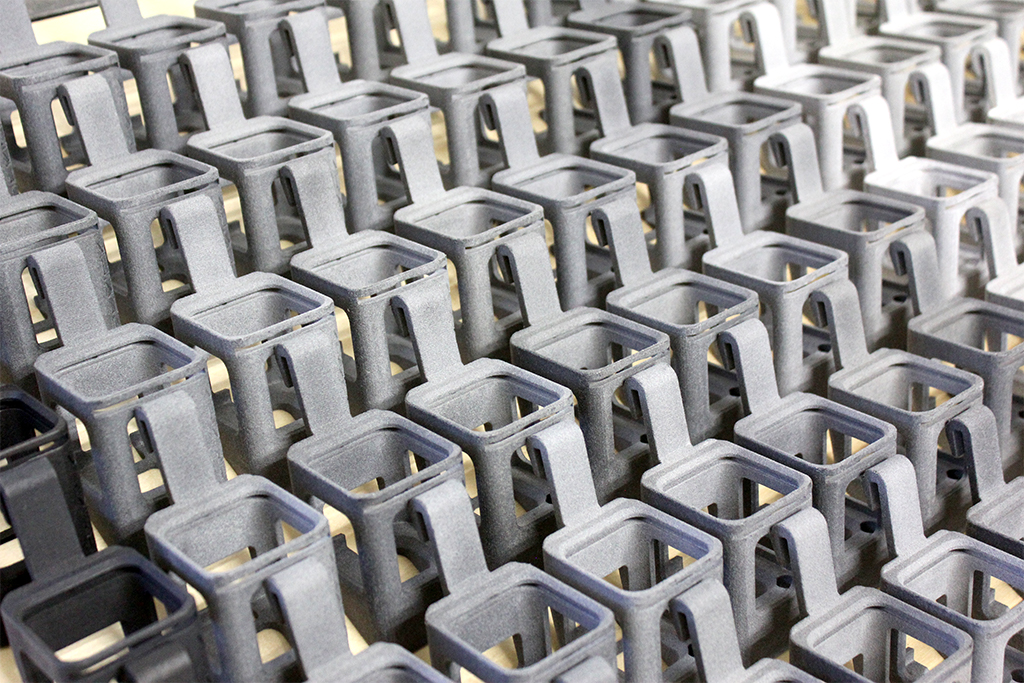
This aircraft-grade aluminum alloy, which is well-suited for laser powder bed fusion 3D printing, lets companies in the aerospace, defense, and military sectors 3D print parts that used to be made through casting. Specific components that VELO3D specializes in 3D printing with Aluminum F357 are for thin-walled heat transfer applications.
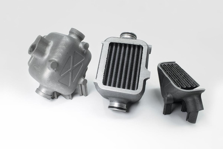
These photos of 3D printed components demonstrate various perspectives of the design freedom that VELO3D’s SupportFree capabilities offer when it comes to heat exchangers.
VELO3D worked with global advanced cooling solutions supplier PWR to develop the Sapphire metal 3D printing process for Aluminum F357. This was a smart partnership, as PWR has provided cooling solutions to several racing series, including Formula 1 and NASCAR, and customers in the aerospace, automotive, and military industries.
Matthew Bryson, General Manager for PWR, said, “We chose Aluminum F357 due to its ideal material properties to suit thermal performance, machining and weldability.
“Our ability to print free-form and lightweight structures for heat transfer applications with our Sapphire system from VELO3D will further enhance performance and packaging optimization opportunities for our product range and provide significant value to our customers.”
VELO3D’s patented SupportFree capability for metal 3D printing means that support structures for steep overhangs, low angles, and complex passageways are not required, allowing users to attain geometric freedom. The Sapphire metal 3D printing system is built with a semiconductor mindset to ensure repeatability in serial manufacturing, and paired with a con-contact recoater, its print process is able to fabricate the high aspect ratios and extremely thin wall structures needed for flight-critical applications.
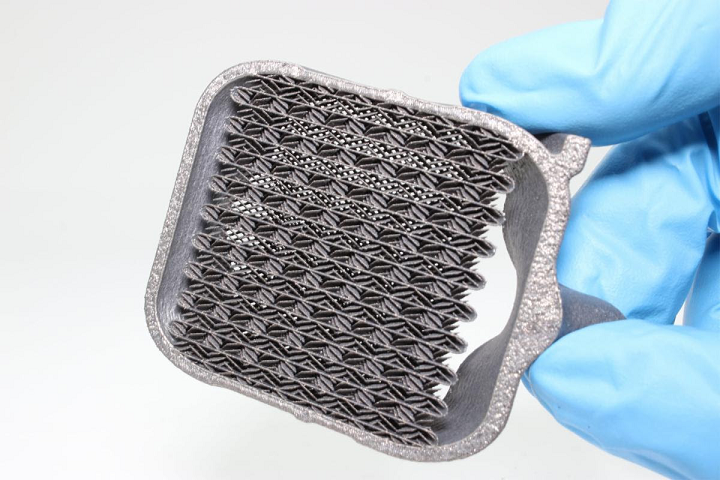
Notice the ultra-thin features in the core (cross-section image). Such complexity is near-impossible to attain with existing AM technologies.
While other aluminum alloys, like AlSi10Mg, are used in metal 3D printing more often, Aluminum F357 is ideal for thin-walled AM applications due to shared characteristics with popular casting alloy A356, and because it can be anodized. SmarTech Analysis reports that aluminum alloys accounted for close to 10% of 3D printed metal content last year, which led to a 43% growth in shipments of aluminum powder. The lightweight material is obviously growing in AM popularity, as VELO3D wasn’t the only company this week to roll out the material – Optomec just announced the use of its LENS DED systems for 3D printing aluminum parts.
VELO3D’s Sapphire metal 3D printer is now compatible with Aluminum F357, INCONEL alloy 718, and Titanium64. If you’re interested in a 3D printed aluminum alloy prototype, contact the company. Last month, VELO3D also announced that a 1-meter tall Sapphire system would be available in Q4 2020 for industrial customers, like Knust-Godwin, interested in using LPBF technology to print tall parts without supports.
Discuss this story and other 3D printing topics at 3DPrintBoard.com or share your thoughts in the Facebook comments below.
The post VELO3D Develops Process for 3D Printing Aluminum F357 on Sapphire Systems appeared first on 3DPrint.com | The Voice of 3D Printing / Additive Manufacturing.
Ultra Realistic Eyes Using 3D Printing and Casting
Eye jokes get cornea and cornea but this is a project you must see!
via Ikkalebob on instructables
In my pursuit to design an effective and reproducible 3D-printed eye mechanism, It became apparent that I would need a reliable system to make realistic eyes. In this instructable I’ll show you the process of making these eyes and provide you with the STLs so that you can make your own.
Make All the Things Part 2: Ring Creation and Casting a Wax Ring, Part 1
A curious mind and a makerspace results in interesting potential. Previously I had explained my intention to create a ring with the materials in my local MakerSpace of Pumping Station One. The last month was dedicated to a bunch of preparation and learning the process. It has been an immense experience that is still continuing, but I will inform everyone about the first developments of this project and follow ups as needed.
Original Ring Design
Firstly, I was curious and wandering around Pumping Station One and learned about the Small Metals Area. I just saw the material there and realized what I could do almost instantaneously. I am a firm component of being able to create items for oneself. It is a very empowering mindset to realize that we can do things for ourselves. Coming up with an idea and driving it to completion is a great feeling and experience. Honestly, it is one of the best feelings I get within this world. But let’s stop my geeking out, and let’s get into the details.
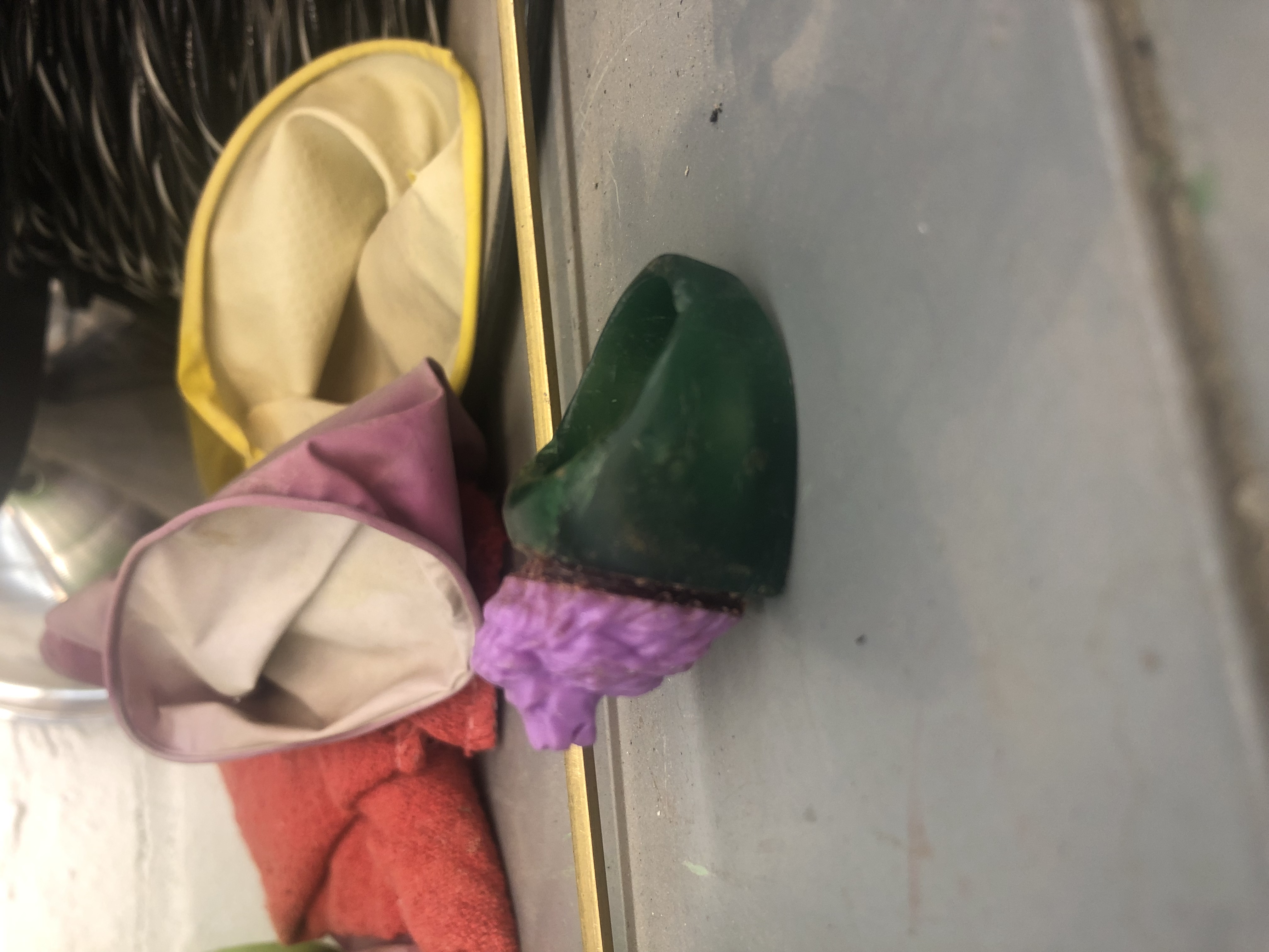
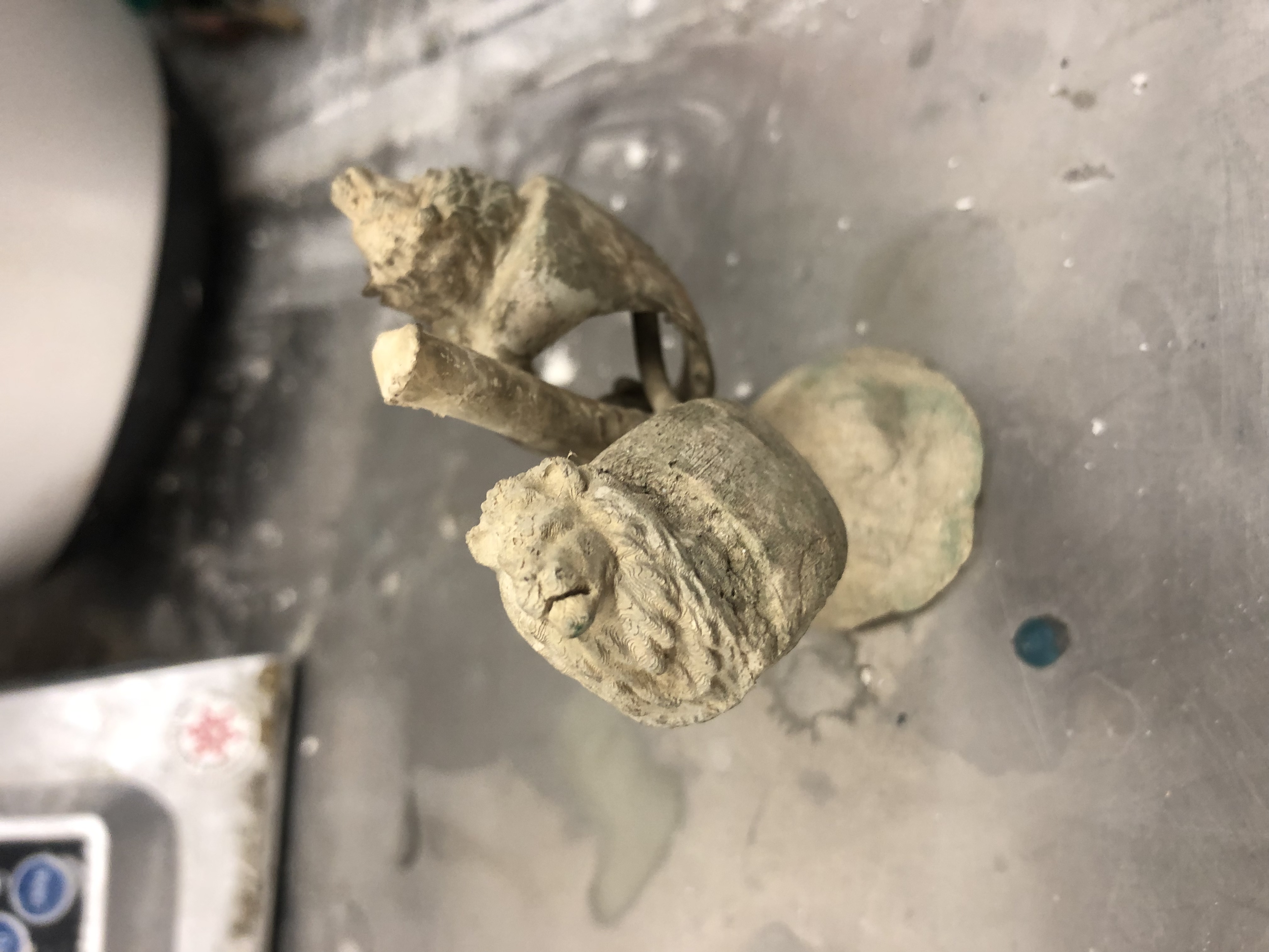
I wanted a lion ring. I then put in substantial effort towards this goal. To create this ring I utilized carver’s wax initially for the body of the piece. Then I found a 3D printed lionhead online that I thought was stylish. This then was used for the front facing design of the model. I attached this onto the ring body with sticky wax in a uniform manner. This then created my prototypical design for a ring. The majority of the work done in this stage was dedicated to sanding, as well as molding the ring, to the specific weight I wanted to use. This work took a couple of days of crafting, but now that I understand the process more, it will take even less time than the next time I want to do this.
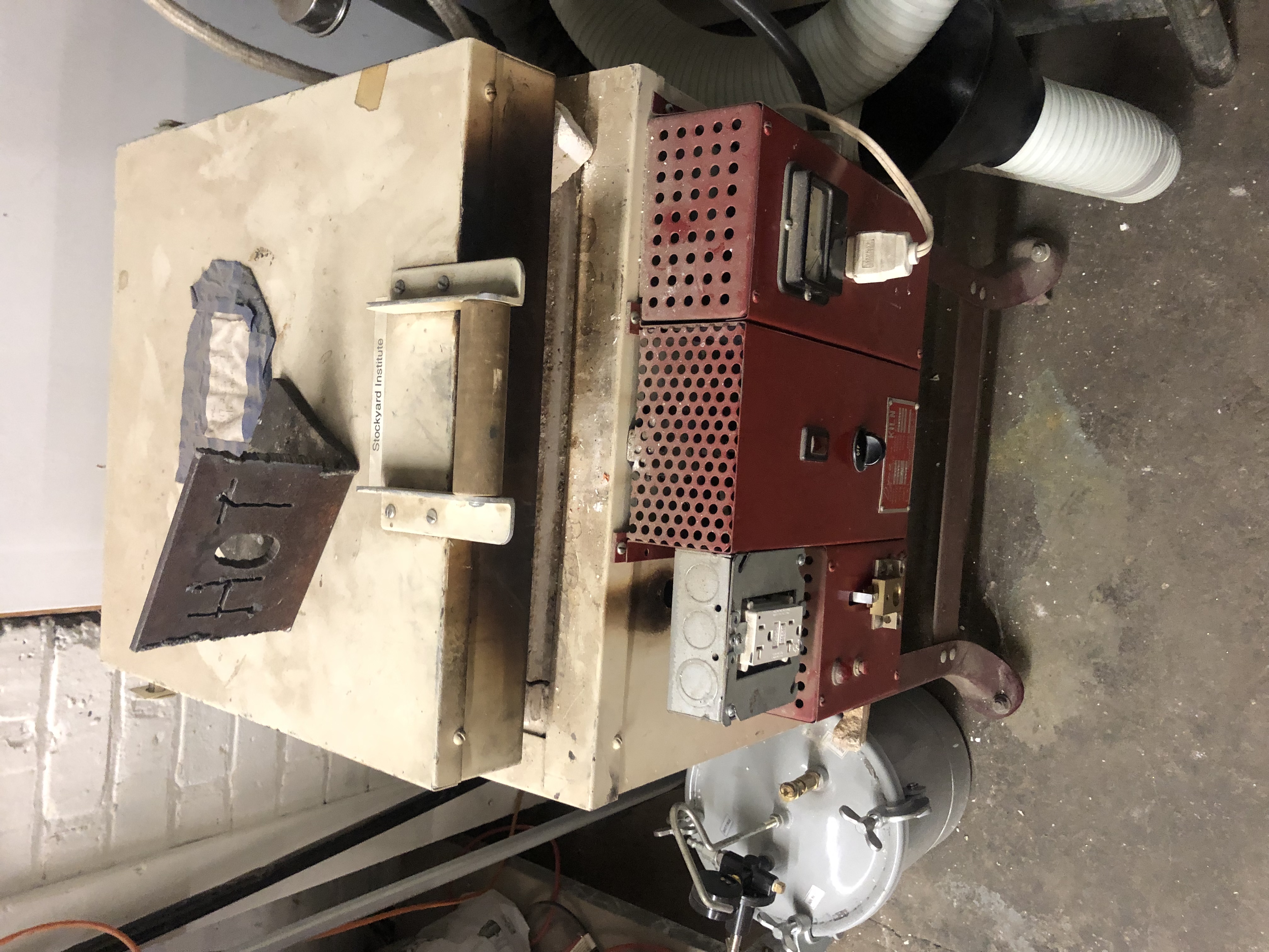
Kiln
The next part of this project was filled with lots of hot wax and continuous failure. Sprues of hot wax are needed in terms of attaching a model. This model is plastic and wax, which means that it will be burned within a kiln for metal creation purposes. Chemistry is a fun thing, but I digress.
The sprues must be attached in almost a tree-like structure in order for an item to be cast from plastic or wax into a metal such as silver. This tree structure is placed in a container. In order to cast this, we utilize silicon powder. The silicon powder is weighed in terms of a conversion sheet that a jeweler would use. Then it is mixed with water in order to create a gel. This gel is placed into the aforementioned container and it is left there until it hardens. Once it hardens the container is prepped for placement within the kiln. Mind you, a kiln temperature is around 1500 degrees Fahrenheit. So it is indeed a dangerous process if one is not careful.
Ring After
Once the container is taken out of the kiln, it is now important to understand the conversion of plastic or wax into metal. The tree like structure built is now flipped upside down. A metal of a choice is also melted at a very high temperature. Again, high temperatures are dangerous. Fortunately, I had the help of people at Pumping Station One. This metal is then poured into the container that was taken out of the kiln. The molten metal travels down the tree-like system and it effectively burns the plastic and wax. The silicon powder essentially holds the piece in place and creates a barrier so that the material does not dissipate and lose form. When the molten metal cools down, the container then may be taken to a water bath for cooling. This then concludes the first part of the process. What is needed after this is post-processing, and I will tackle that in a new article.
The post Make All the Things Part 2: Ring Creation and Casting a Wax Ring, Part 1 appeared first on 3DPrint.com | The Voice of 3D Printing / Additive Manufacturing.
Researchers Compare Microstructure of As-Cast, Hot-Extruded, and 3D Printed Magnesium Alloy Samples
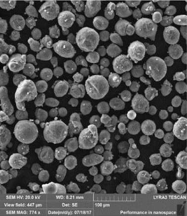
Fig. 1: SEM micrographs of the WE43 alloy powder
Alloys of the shiny gray chemical element magnesium (Mg) feature a high strength-to-weight ratio and a low density of about 1700 kg/m3, making them good options for technical applications in the automotive, aviation, and medical fields. But it’s been determined that their weight can be further decreased if porous structures are formed – which can be achieved with 3D printing. A team of researchers from the University of Chemistry and Technology Prague and the Brno University of Technology, both in the Czech Republic, wanted to study the microstructure of a particular magnesium alloy after it had been fabricated using three different methods: as-cast, hot-extruded, and 3D printed with SLM technology.
SLM 3D printing can achieve complex geometric shapes, but there are issues when it comes to fabricating magnesium alloys with this process, mainly high reactivity of magnesium powder, which can lead to unsafe oxide particles forming within 3D printed parts. Patrícia Krištofová, Jiří Kubásek, Dalibor Vojtěch, David Paloušek, and Jan Suchý recently published a study, titled ” Microstructure of the Mg-4Y-3RE-Zr (WE43) Magnesium Alloy Produced by 3D Printing,” about their work mapping an SLM 3D printed magnesium alloy’s microstructure.
“Magnesium alloys made in the form of 3D printing are relatively new production processes,” the researchers wrote. “The study therefore this process compared with current processes, which are now well known and mapped. It was therefore studied the microstructure produced by three different processes of production. The microstructure and chemical composition of present phases were studied using scanning electron microscopy (SEM) and energy dispersive xray spectrometry (EDS). Based on the microstructural examination, significant differences were found between the materials produced by different production processes. The microstructure of the as-cast alloy consisted of relatively coarse α-Mg dendrites surrounded by eutectics containing intermetallic phases rich-in alloying elements. During hot extrusion, the eutectics fragmented into fine particles which arranged into rows parallel to the extrusion direction. The 3D printed alloy was characterized by significantly refined microstructure due to a high cooling rate during the SLM process. It consisted of very fine dendrites of α-Mg and interdendritic network enriched-in the alloying elements. In addition, there were also oxides covering original powder particles and the material showed also some porosity that is a common feature of 3D printed alloys.”
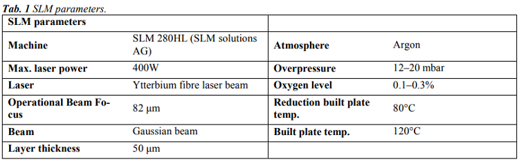
The team used an SLM Solutions 280HL 3D printer to fabricate 15 × 5 × 60 mm rectangular samples of WE43 magnesium alloy, and used SEM and EDS to study their microstructures; then, these were compared to identical materials that had been manufactured through simple gravity casting and hot extrusion.
“The first sample was an as-cast ingot of 60×80×500 mm in size purchased from an industrial supplier. The second WE43 alloy sample was prepared by hot extrusion of the ingot. Cylinders with a diameter of 30 mm and a length of 60 mm were directly cut from the ingot and then extruded at 400°C, extrusion rate of 2 mm/s and extrusion ratio of 16. The resulting extruded rods had a diameter of 7.5 mm,” the researchers explained.
“The analysis revealed that 10% of the WE43 alloy powder particles had a size of 26.9 μm, 50% to 39.8 μm and 90% to 57.9 μm. Thus, the powder contains a sufficient amount of both larger and smaller particles. With respect to the particle size, the size of the building layer was 50 μm.”
The team conducted microscopic observations of the samples, and you can see the views of their microstructures in Figure 2.
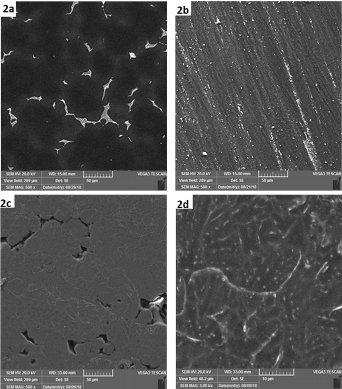
Fig. 2: SEM micrographs of the WE43 alloy: a) as-cast, b) hot extruded, c) 3D printed by SLM, d) 3D printed by SLM – detail.
The as-cast alloy has a coarse microstructure, while the microstructure of the sample fabricated with hot extrusion was “considerably” modified. The microstructure of the 3D printed sample is completely different from the other two, featuring regions about 20-50 µm in size that are surrounded by thin boundaries.
“In addition, residual porosity is observed as dark areas between grey regions. The shape and size of grey regions indicates that these regions correspond to original powder particles, either totally or partly melted by laser beam,” the researchers explained. “A more detailed image in Fig. 2d shows very fine internal microstructure of these particles. It contains α-Mg dendrites (dark) surrounded by interdendritic regions (light) enriched in Y and RE elements. The average thiskness of dendritic branches is only approx. 3 µm, suggesting very high cooling rates during the SLM process. In literature focused on the SLM process, cooling rates of 103-106 K/s are often reported.”
The researchers also studied the distribution of elements in the material’s structure, which showed that both the hot-extruded and as-cast material samples had very low oxygen concentration. But the SLM 3D printed sample showed a different story, illustrated in Figure 5 and Table 4.
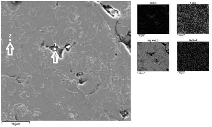
Fig. 5 Microstructure of the SLM WE43 alloy (SEM) and elements distribution maps (EDS).

“First, element maps and point analysis demonstrate an increased concentration of oxygen in the material which is located mainly in pores (point 1) and also at bondaries between melted powder particles. In the particle interior the O-concentration is very low (point 2),” the researchers wrote. “Second, element map in Fig. 5 also indicates increased content of Y at powder particle boundaries. It can be assumed, that partial oxidation of the powder occurred during the SLM process inside the building chamber. Most probably, the atmosphere contained traces of residual oxygen which reacted preferentially with yttrium due to a high chemical affinity of these elements. For this reason, imperfect connection between powder particles and porosity are observed.”
Results show that an SLM material’s microstructure is “extremely fine” because of high cooling rates, and will also feature a high oxygen concentration “due to a high affinity of the alloy to this gas.” This creates an “imperfect connection” between powder particles and porosity. The researchers plan further studies of this magnesium alloy in order to produce pore-free compact material and decrease the “harmful influence of residual oxygen.”
Discuss this research and other 3D printing topics at 3DPrintBoard.com or share your thoughts below.
The post Researchers Compare Microstructure of As-Cast, Hot-Extruded, and 3D Printed Magnesium Alloy Samples appeared first on 3DPrint.com | The Voice of 3D Printing / Additive Manufacturing.
Interview with Ken Burns of Forecast3D on Manufacturing as a Service
I was very impressed with Ken Burns’ presentation at Additive Manufacturing Strategies in Boston. Ken is the technical sales director of the 3D printing services and manufacturing company Forecast3D. Originally set up to do urethane casting, the company now deploys HP MJF, FDM, DMLS, SLA, and Polyjet 3D printing technologies as well as casting. Focusing on bridge manufacturing and short-run production the company recently has bet big on MJF as a manufacturing technology. Many bureaus are continually under threat and expanding because of renewed interest in 3D printing. On the one hand, 3D printing news brings in new customers but some of these then switch to desktop and in house 3D printing. Can service bureaus cross the chasm and play a role in manufacturing millions of products with 3D printing? Or will they succumb to pressures from much larger firms? In different verticals we see that companies are taking very different approaches to adopt 3D Printing while in some industries there is a sharp division between the outsourcers and companies that do in house 3D printing. In medical device, for example, some companies are making huge investments in doing in house production while others immediately outsource. Millions of hearing aids are made in house while only car companies have significantly invested in taking prototyping in house. It is a very exciting time to be a pioneering 3D printing service so we asked Ken to tell us more.
How did Forecast3D get started?
Forecast 3D started with two brothers: Corey & Donovan Weber when they were in their early 20’s. They started in their garage and eventually purchased a single SLA machine (with the help of a loan from their grandfather). Corey developed an innovative method for urethane casting, which helped establish them and differentiate them from other service providers.
How did you go from a regional player to a national one?
Having a strong, reliable, and passionate team that gave our early customer base a unique customer experience and dedicated customer service – this helped us to grow our technology offerings and be able to afford to adopt the latest equipment. It sounds cliché but we listened to what customers needed and answered by creating a national team. Whether it is a phone call or a face-to-face meeting we were committed to the resources to engage with our customers however the needed us. We have also never been complacent with our technology, processes and business systems.
You seem to have always been at the forefront of adopting new technologies. In hindsight, it all looks beautiful but surely you’ve also gotten bitten by adopting new technologies?
We wouldn’t say any of the technologies “bit us” but we have certainly had more success with some over others. The technologies all promise something “ground-breaking”; which is true to an extent, but it doesn’t mean they are the right fit for our business model. We have target customers and industries so we focus on technologies that can help us be successful with that lens. So if we miss the mark, it is usually a small miss.
Do you still do a lot of casting?
Absolutely. Like most traditional processes, they are not going away. In fact, 3D printing has helped improve some of these services like casting. We can do hybrid processes with casting and 3D printing. Casting is and remains a long term focus for us.
What do your customers use Polyjet for?
Fast prototypes – attractive show models. When they want full color parts, or parts with multiple materials and durometers in a single piece. Often used in the entertainment industry.
And FDM?
Robust parts – used in aerospace and automotive mostly, often when demanding environments (high heat resistance, chemical resistance, UV stability) are present. When part strength (and not so much aesthetics) is a priority.
What do you use DMLS for?
Prototype and end-use parts. Often times when a smaller quantity of metal parts is needed, and the geometry would be impossible or too difficult to machine.
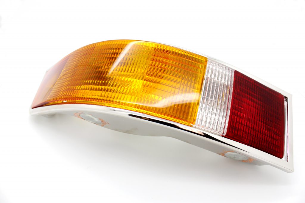
SLA Chrome plated award part.
What was it like buying an SLA machine in 1996?
Exciting. It is still exciting to buy new 3D printing equipment in 2019. To be on the forefront of the 3D printing industry in the 90s was an incredible opportunity.
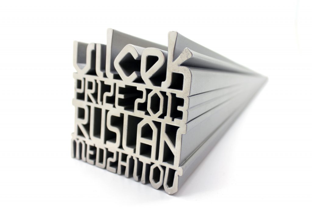
A ProCast Part.
What is ProCast?
Our proprietary urethane casting process, used for producing a short-run (4 to 400) quantity of parts. Often times the next step after a single prototype, and used when only low volume production is needed (product lines that don’t require thousands of parts). We typically start by 3D printing a master model using SLA, FDM, or PolyJet. Then the master model is sanded and finished to the customer’s desired surface finish/texture, and then that part is encapsulated into a silicone mold (which is the soft tool). And from that mold, we produce 20-30 parts at a time. We can cast in any color or texture.
What new technologies are you excited about?
There is a lot to be excited about these days. On the metals side you have a lot of movement with HP’s Metal Jet, DesktopMetal’s Production System, GE Additive and a few others. In the plastics space we are watching a lot of the OEMs looking at solving new problems…HP MJF’s color printer, Carbon, Evolve and Titan Robotics are a few that seem to be doing something different. We are also looking at a lot of technologies surrounding the printer ecosystem from software to automation equipment.
What advice would you give me if I were a company new to 3D printing?
Be realistic with what you are going to do with 3D printing. It’s not the silver bullet that solves all problems. It can be an amazing tool for prototyping or production if you have a good approach. Working with a service provider to test and qualify which technology is always a great start as you can assess lots of technologies.
What about if my firm wanted to use 3D printing for manufacturing?
Yes, there are several technologies now capable of manufacturing. We primarily use the HP’s Multi Jet Fusion (MJF), Stratasys Fused Deposition Modeling (FDM) and SLM (metals) technologies for manufacturing. Our 3D Manufacturing center has 24 of the HP MJF systems so we have the capacity to print tens of thousands of production parts a day. Industries like Aerospace and Healthcare have been taken advantage of FDM and SLM processes in production.
Is lack of automation in post processing holding 3D printing back?
Yes. Until recently there wasn’t a big demand for this type of equipment because there wasn’t a lot of production in high volumes happening in 3D printing; outside of a few niche applications. We have surveyed the market and while some equipment works we have spent a lot of our time developing these tools.
You seem to have taken a big bet on MJF?
Oh yes. We believe in the technology, and its ability to take 3D printing to the next level (beyond being used primarily for prototyping).
Why?
One word. Production. We want to go after high volume production opportunities in manufacturing. We firmly believe this technology is solving new problems and creating new opportunities for our customers. We have already seen it utilized in many great applications and expect that it grows exponentially over the next several years.
What do you use the MJF machines for?
Production. We also do a lot of prototyping with them. There are certainly applications and industries it is better suited for as we are limited by materials, part size, surface finish and a few other constraints.
What is the market like now for a service bureau?
The service bureau market has certainly changed over the last few years. There are several companies focusing on the software component and it some ways attempting to commoditize the space while others have differentiated with specific technologies. We have been position Forecast 3D as a Digital Manufacturing company. Going beyond typical service bureau capabilities to meet the requirements for production. With so many service bureaus we think it is important to focus on what you do best and execute that with laser focus.
When Should 3D Printing Be Used in Sand Casting?
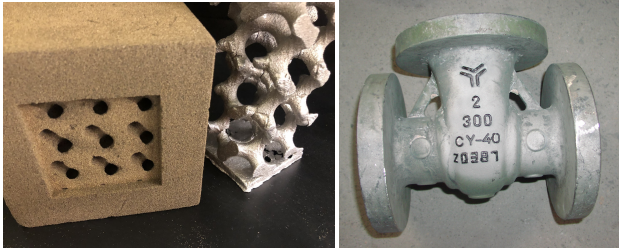
Complex casting with 3D printed mold (left) and traditional casting with traditional cores and molds (right)
Sand casting is a technology with a long history, but it’s being reinvented by additive manufacturing. 3D printed sand molds allow for highly geometrically complex castings, and in a paper entitled “Economies of Complexity of 3D Printed Sand Molds for Casting,” a group of researchers outlines the benefits of using additive manufacturing in sand casting:
- the integration of structural elements such as periodic lattices in order to optimize weight versus strength
- the structural inclusion of unique features such as embossed part numbers and/or other details of the production history
- complex geometries that generate new casting applications not possible previously
In the paper, the researchers describe a complexity evaluation tool that scores CAD models to determine the most economical casting approach based on slicing and 2D geometry evaluation. The three potential outcomes include traditional sand casting; AM-enabled sand casting and a hybrid of the two with 3D printed cores in traditional casting flasks.
“Four algorithms were developed that all began by slicing each of the benchmark STL files and performing analysis per layer producing an average complexity across all layers,” the researchers explain. “This process was repeated for three orientations of each part and the results were averaged including: an unrotated case, a rotated case 90 degrees in X axis and rotated 90 degrees in Y axis. The rotations were completed in order to detect a complexity bias relative to orientation. For each orientation, the complexity numbers from all layers were individually calculated and then the total was divided by the number of layers for a mean value that was independent of the number of slices selected. By using more layers, the accuracy was expected to improve by improving the statistical sampling; however each additional layer meant an increase in the duration of computation.”
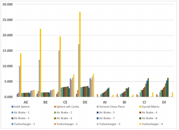
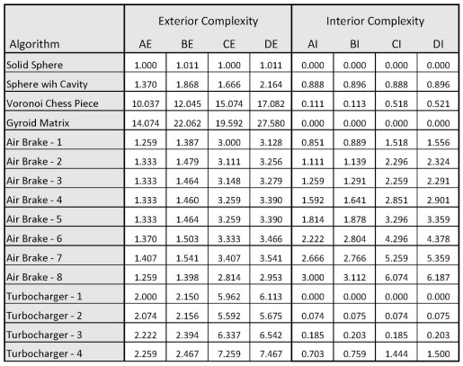
The complexity factor values for Algorithms AD are shown for each of the benchmark castings. E indicates exterior. I indicates interior.
Algorithm A was the simplest and summed the number of contours detected for each layer. Algorithm B was similar to A except that instead of incrementing the sum of contours, a ration was calculated and added to a running sum. Algorithm C summed the number of contours but also included a sum of concavity defects that were sufficiently concave. Algorithm D was an aggregate of the other algorithms: the contours, the ratio of perimeter over area and the number of concavity defects summed together.
16 structures were selected for casting, ranging in complexity from simple spheres to a gyroid matrix and a Voronoi tesselation chess piece. The different castings were run through the complexity software, and the resulting data was compared to complexity scores assigned by previous work in which the scores were generated manually and correlated well with the decision as to which casting process was most suitable.
Of the four algorithms, Algorithm D gave values that “provide a decision boundary that was in line with the intuition of the authors as well as obvious extreme cases (sphere as a case of simplicity or a gyroid matrix for a case that can only be cast with the help of 3D printing),” according to the researchers.
“This layerwise complexity factor was compared to a known complexity factor for conventional casting fabrication method and showed similar results but without requiring design knowledge of the traditional methods,” the researchers state. “The economics of complexity and quantity were shown for a traditional casting tooling method and then compared to three methods that involved additive manufacturing.”
The researchers presented four options:
- Traditional manufacturing (TM): Traditional subtractive processes to make molds / cores.
- 3D Sand Printing (3DSP): Complete sand printing of both molds and cores.
- 3D Sand Printed Core (3DSPC): 3D sand printing of cores and conventional pattern making for the mold cope and drag.
- FDM Patternmaking (FDMP): Conventional core making and 3D printing using fused deposition modeling of hard patterns for conventional mold making with the advantage of faster mold fabrication.
The most economical method depended on the complexity and quantity of the parts being made. For example, for an air brake, 3DSP was the most cost effective regardless of level of complexity. However, 3DSPC was the most cost effective for more complex objects or objects in quantities of 100 or higher. For castings of low complexity, FDMP was the best choice, while for quantities of 1,000 3DSPC was the most cost effective for the full range of complexities.
Authors of the paper include Ashley Martof, Ram Gullapalli, Jon Kelly, Allison Rea, Brandon Lamoncha, Jason M. Walker, Brett Conner and Eric MacDonald.
Discuss this and other 3D printing topics at 3DPrintBoard.com or share your thoughts below.