What is Metrology Part 22 – 3D Translation and Rotation

3D Translation

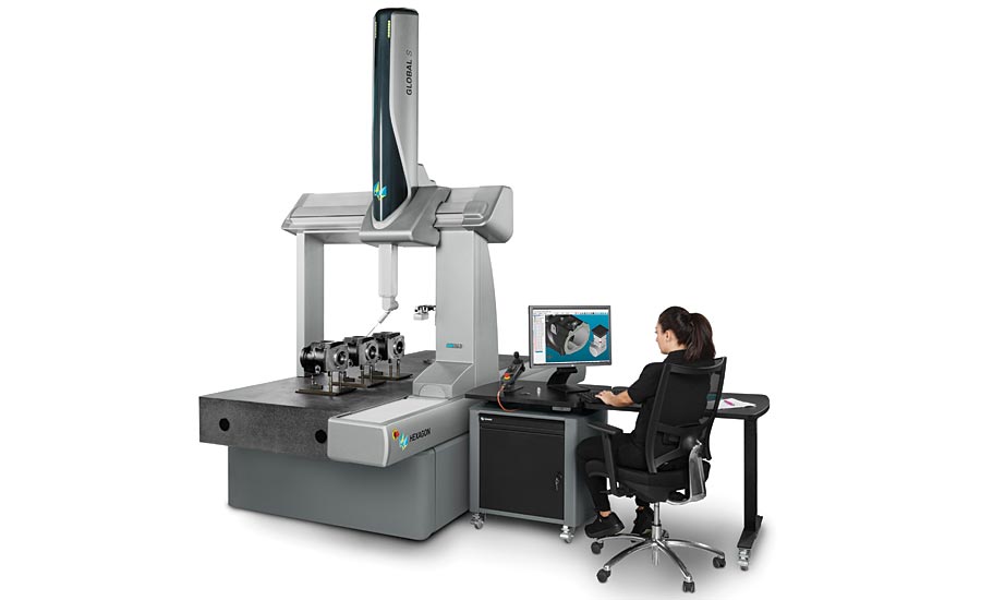
3D translation and rotation is vital within a 3D environment. We have discussed the importance of this within metrology previously in CMM systems. Interfacing the physical world and digital world requires precise measurement coordinates. Within 3D environments, movement is vital. In particular, movement is our focus today. We will talk about how example code within Processing can help us interface the digital world and physical realm. How does one simulate the real world within a virtual space? VR and 3D build environments are critical. So what are the basics needed for measurement and calculating space in a digital field? Metrology systems and laser scanning help. Tracking movement in terms of translation within a coordinate system is vital. So how could we learn about the basics of all of this? Let’s look into Processing as our main digital coding tool. How does Processing compute translational movement? If one wants to understand coding in a 3D environment, it is highly recommended that you understand object oriented program. We will not do a deep dive into this today, but a lot of the operations we are doing are object oriented. The following code is how I will demonstrate movement within Processing:

size(640,360,P3D);

background(0);

lights();

pushMatrix();

translate(130, height/2, 0);

rotateY(1.25);

rotateX(-0.4);

noStroke();

box(100);

popMatrix();

pushMatrix();

translate(500, height*0.35, -200);

noFill();

stroke(255);

sphere(280);

popMatrix();

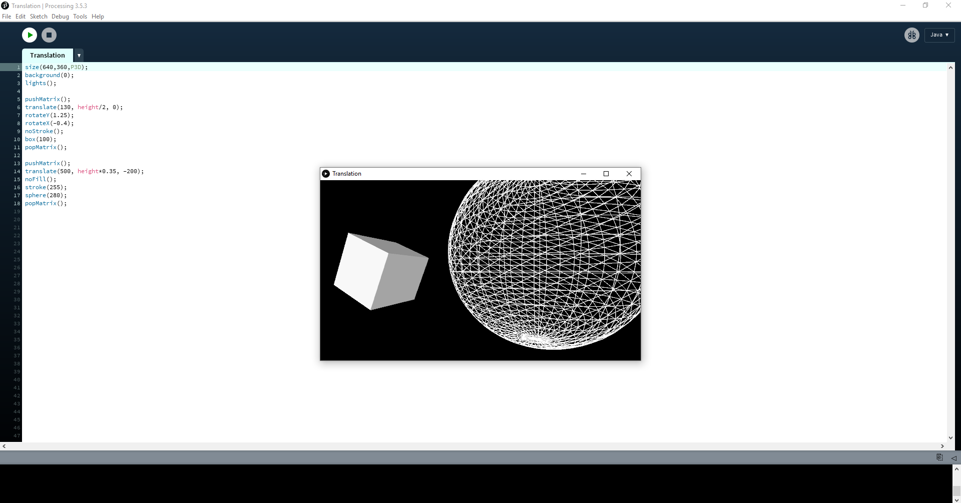
Processing Example Code

Let’s take a look at this line by line. The first line is dedicated to building the 3D environment. The background of this window is denoted by the color value 0 which corresponds to black. The lights() function allows us to use ambient light, directional light, and specular values within our environment. In this case we are using the default light structure. pushMatrix(), we have discussed before as a function that allows us to set our original matrix of data that will be manipulated later. Our manipulation will come in the form of translational and rotational forces implemented. translate(130, height/2, 0) manipulation in question. The rotateY() function is used to move the window towards a particular angle based on units from the Y-axis of our viewport. The rotateX() function is similar except it is rotating within the X-axis. noStroke() allows us to be free from bordered 3D image renderings. box(100) allows us to create a 3D box with a float dimension of 100 in the x-dimension. popMatrix() ends the manipulation of the original data set. We then are able to start a new data manipulation through translation with pushMatrix(). This time, we have used the following command to apply a translation: translate(500, height*0.35, -200). Instead of a box though, we created a sphere for rotation.

Planar Rotation

We have focused a lot on coding basics within this metrology series as a whole. Being able to have standardized measuring devices within our metrology equipment is key. Without such, we would lack tangibility. If a 3D environment cannot be built with a computer, there is no way to interpret the data from a 3D world that we interact with. Being able to set a coordinate based on the world around us is still a difficult task though. So how can we do this? It makes us question how most of the devices we use in metrology are able to accurately set values of measurements based on the real world. These set of questions are things I would further like to explore.

The post What is Metrology Part 22 – 3D Translation and Rotation appeared first on 3DPrint.com | The Voice of 3D Printing / Additive Manufacturing.

What is Metrology Part 2: CMM

Image result for cmm

CMM

A CMM is a widely used machine used to measure objects. A CMM is a coordinate measuring machine. This refers to any machine that measures the geometry of physical objects by sensing discrete points on the surface of the object with a probe. This is the essence of many a metrology system. The precision of a CMM is vital for determining the geometry of objects. This then leads to more precision in the manufacturing and replication of objects. 

Probes are the engine of a CMM. They sense objects through their surfaces. There are various types of probes as well.  The types of probes used in CMMs include mechanical, optical, laser, and white light. Mechanical probes typically have a ball and rod looking setup attached to them, or have a nozzle setup. These physically touch the surface of a material that is in need of measuring. Optical probes typically refer to spectral analysis and measuring through these means. One can think of a fiber optic probe in particular. These type of probes are usually used in Raman spectroscopy, and diffuse reflection applications. Raman spectroscopy is a spectroscopic technique based on inelastic scattering of monochromatic light, usually from a laser source. Inelastic scattering means that the frequency of photons in monochromatic light changes upon interaction with a sample. The scattering of the photons within a monochromatic light source allows for a device to detect if an object is within the path of monochromatic light. This thus leads to measuring capabilities that are important in terms of a CMM as well. Diffuse reflection is similar to Raman Spectroscopy aside from the optical source is typically infrared. When an IR beam passes through a physical object, it can be reflected off the surface of a particle or be transmitted through a particle. The IR energy reflecting off the surface is typically lost. This transmission‐reflectance event can occur many times in the object, which increases the pathlength. This pathlength is vital for measuring. Finally, the scattered IR energy is collected by a spherical mirror that is focused onto the detector. The detected IR light is partially absorbed by particles of the object, collating the object information.

Image result for raman spectroscopy

Typical Raman Spectroscopy Setup

A CMM is heavily reliant on a built-in coordinate system of, typically, three axes. This is similar to the coordinate systems we are aware of within a 3D build environment. This is a Cartesian Coordinate system. The main structure of which includes three axes of motion. The material used to construct the moving frame has varied over the years. Granite and steel were used in the early CMM ‘s. Today the major CMM manufacturers tend to build frames from aluminium alloy or some derivative and also use ceramic to increase the stiffness of the Z axis for scanning applications. CMM axises need to be stiff because there should be minimal outside inference with forces that may misalign the device during measurement. Any misalignment will cause higher error ranges for measurement. 

Image result for cartesian coordinate system

Cartesian Coordinate System

Scanning techniques are becoming more reliant on data collection and compilation. These methods use either laser beams or white light that are projected against the surface of a part. Thousands of points can then be taken and used not only to check size and position but also to create a 3D image of the part also. This “point-cloud data” can then be transferred to CAD software to create a working 3D model of the part. The ability to hold various point cloud data from these methods is essential for the future development of the field. Big data is something of interest most definitely for this field. 

CMM’s are very interesting and are the basis of most metrology methods. It is important to understand how in-depth and fascinating this field is. It is a very vital one as well for the future in terms of 3D printing and manufacturing. Stay tuned for the next installment where we take a look into different subfields within Metrology as well.

The post What is Metrology Part 2: CMM appeared first on 3DPrint.com | The Voice of 3D Printing / Additive Manufacturing.

KREON Technologies release new 3D scanner, the Zephyr III

KREON Technologies, a French manufacturer of metrology equipment, has released its latest high-end 3D scanner, the Zephyr III. With a 150mm laser line, the Zephyr III scans complex parts efficiently and is unhindered by previously difficult black or glossy surfaces. The Zephyr III Debuting at the Control Trade Fair in Stuttgart, Germany earlier this month, the […]