Researchers Compare Microstructure of As-Cast, Hot-Extruded, and 3D Printed Magnesium Alloy Samples

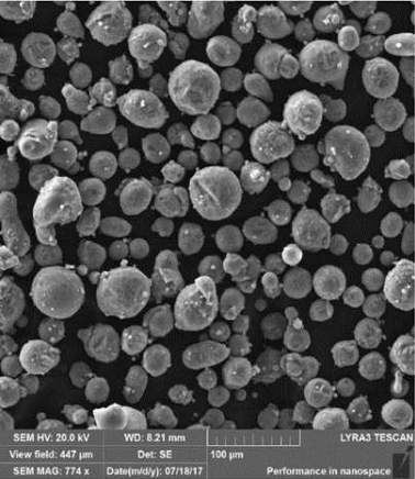
Fig. 1: SEM micrographs of the WE43 alloy powder

Alloys of the shiny gray chemical element magnesium (Mg) feature a high strength-to-weight ratio and a low density of about 1700 kg/m3, making them good options for technical applications in the automotive, aviation, and medical fields. But it’s been determined that their weight can be further decreased if porous structures are formed – which can be achieved with 3D printing. A team of researchers from the University of Chemistry and Technology Prague and the Brno University of Technology, both in the Czech Republic, wanted to study the microstructure of a particular magnesium alloy after it had been fabricated using three different methods: as-cast, hot-extruded, and 3D printed with SLM technology.

SLM 3D printing can achieve complex geometric shapes, but there are issues when it comes to fabricating magnesium alloys with this process, mainly high reactivity of magnesium powder, which can lead to unsafe oxide particles forming within 3D printed parts. Patrícia Krištofová, Jiří Kubásek, Dalibor Vojtěch, David Paloušek, and Jan Suchý recently published a study, titled ” Microstructure of the Mg-4Y-3RE-Zr (WE43) Magnesium Alloy Produced by 3D Printing,” about their work mapping an SLM 3D printed magnesium alloy’s microstructure.

“Magnesium alloys made in the form of 3D printing are relatively new production processes,” the researchers wrote. “The study therefore this process compared with current processes, which are now well known and mapped. It was therefore studied the microstructure produced by three different processes of production. The microstructure and chemical composition of present phases were studied using scanning electron microscopy (SEM) and energy dispersive xray spectrometry (EDS). Based on the microstructural examination, significant differences were found between the materials produced by different production processes. The microstructure of the as-cast alloy consisted of relatively coarse α-Mg dendrites surrounded by eutectics containing intermetallic phases rich-in alloying elements. During hot extrusion, the eutectics fragmented into fine particles which arranged into rows parallel to the extrusion direction. The 3D printed alloy was characterized by significantly refined microstructure due to a high cooling rate during the SLM process. It consisted of very fine dendrites of α-Mg and interdendritic network enriched-in the alloying elements. In addition, there were also oxides covering original powder particles and the material showed also some porosity that is a common feature of 3D printed alloys.”

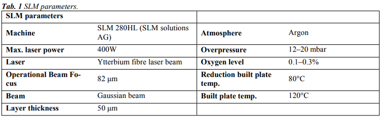
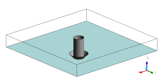
The team used an SLM Solutions 280HL 3D printer to fabricate 15 × 5 × 60 mm rectangular samples of WE43 magnesium alloy, and used SEM and EDS to study their microstructures; then, these were compared to identical materials that had been manufactured through simple gravity casting and hot extrusion.

“The first sample was an as-cast ingot of 60×80×500 mm in size purchased from an industrial supplier. The second WE43 alloy sample was prepared by hot extrusion of the ingot. Cylinders with a diameter of 30 mm and a length of 60 mm were directly cut from the ingot and then extruded at 400°C, extrusion rate of 2 mm/s and extrusion ratio of 16. The resulting extruded rods had a diameter of 7.5 mm,” the researchers explained.

“The analysis revealed that 10% of the WE43 alloy powder particles had a size of 26.9 μm, 50% to 39.8 μm and 90% to 57.9 μm. Thus, the powder contains a sufficient amount of both larger and smaller particles. With respect to the particle size, the size of the building layer was 50 μm.”

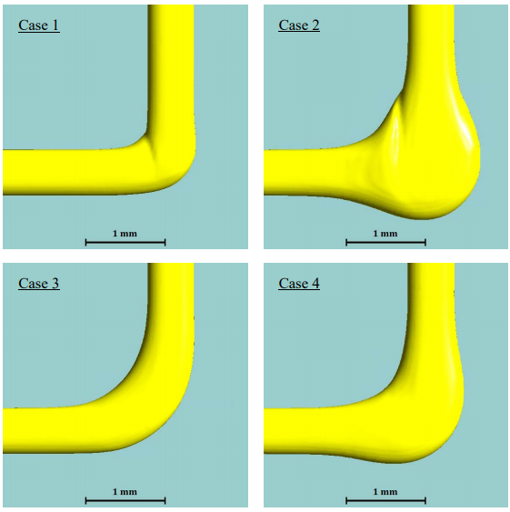
The team conducted microscopic observations of the samples, and you can see the views of their microstructures in Figure 2.

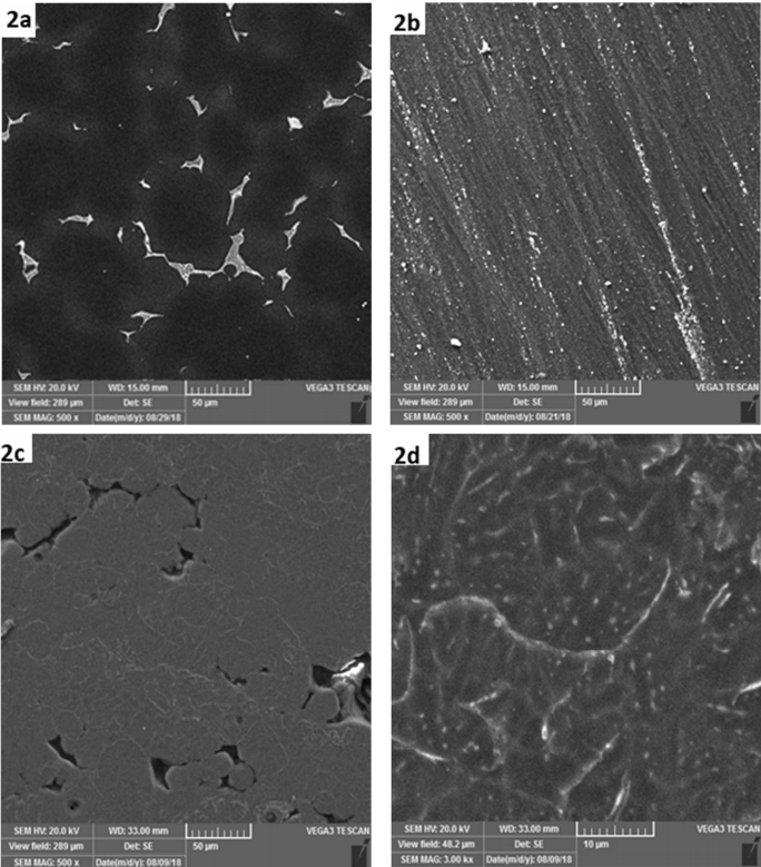
Fig. 2: SEM micrographs of the WE43 alloy: a) as-cast, b) hot extruded, c) 3D printed by SLM, d) 3D printed by SLM – detail.

The as-cast alloy has a coarse microstructure, while the microstructure of the sample fabricated with hot extrusion was “considerably” modified. The microstructure of the 3D printed sample is completely different from the other two, featuring regions about 20-50 µm in size that are surrounded by thin boundaries.

“In addition, residual porosity is observed as dark areas between grey regions. The shape and size of grey regions indicates that these regions correspond to original powder particles, either totally or partly melted by laser beam,” the researchers explained. “A more detailed image in Fig. 2d shows very fine internal microstructure of these particles. It contains α-Mg dendrites (dark) surrounded by interdendritic regions (light) enriched in Y and RE elements. The average thiskness of dendritic branches is only approx. 3 µm, suggesting very high cooling rates during the SLM process. In literature focused on the SLM process, cooling rates of 103-106 K/s are often reported.”

The researchers also studied the distribution of elements in the material’s structure, which showed that both the hot-extruded and as-cast material samples had very low oxygen concentration. But the SLM 3D printed sample showed a different story, illustrated in Figure 5 and Table 4.

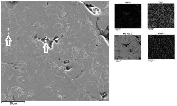
Fig. 5 Microstructure of the SLM WE43 alloy (SEM) and elements distribution maps (EDS).

“First, element maps and point analysis demonstrate an increased concentration of oxygen in the material which is located mainly in pores (point 1) and also at bondaries between melted powder particles. In the particle interior the O-concentration is very low (point 2),” the researchers wrote. “Second, element map in Fig. 5 also indicates increased content of Y at powder particle boundaries. It can be assumed, that partial oxidation of the powder occurred during the SLM process inside the building chamber. Most probably, the atmosphere contained traces of residual oxygen which reacted preferentially with yttrium due to a high chemical affinity of these elements. For this reason, imperfect connection between powder particles and porosity are observed.”

Results show that an SLM material’s microstructure is “extremely fine” because of high cooling rates, and will also feature a high oxygen concentration “due to a high affinity of the alloy to this gas.” This creates an “imperfect connection” between powder particles and porosity. The researchers plan further studies of this magnesium alloy in order to produce pore-free compact material and decrease the “harmful influence of residual oxygen.”

Discuss this research and other 3D printing topics at 3DPrintBoard.com or share your thoughts below.

The post Researchers Compare Microstructure of As-Cast, Hot-Extruded, and 3D Printed Magnesium Alloy Samples appeared first on 3DPrint.com | The Voice of 3D Printing / Additive Manufacturing.

3D Printed Meat: Great Potential for the Future, But Challenges Still Persist

In ‘Application of 3D Printing in Meat Production,’ researchers delve further into the possibilities of additive manufacturing with food. While there have been some forays into 3D fabrication with meat, most viable production of food has related more to extrusion of sweets, breads, and items more conducive to being expressed through a nozzle. The authors point out that some of the greatest benefits in 3D printing can be translated to use with food as so many consumers today have special dietary needs—and 3D printing technology allows for complete customization, even with the possibility of adding specific vitamins to food, along with flavors and different structures.

Food customization is certainly nothing new, as chefs around the world have been creating special dishes for eons; however, ‘artisans’ today are often challenged in creating one-of-a-kind dishes as such an exercise can be cost-prohibitive.

Hypothetical 3D printed meats such as a) sausage, b) steak, c) patty

“Digital gastronomy brings in cooking knowledge into food fabrication so that our eating experience can go beyond merely taste and cover all the aspects of gastronomy,” state the researchers.

So many different health conditions can be addressed too, and especially for individuals who may have trouble eating, chewing, or swallowing their food. The research team explains that the greatest potential for customized food lies in 3D printing techniques such as:

  • Extrusion
  • Inkjet printing
  • Binding deposition
  • Bioprinting

Their number one choice for creating food, however, is a natural one, with extrusion:

“The syringe-based extrusion unit is suitable to print food materials with high viscosity and high mechanical strength, to fabricate complex 3D structures with high resolution. The air pressure-based extrusion and syringe-based extrusion do not allow the continuous feeding of food materials during printing. The viscosity of the soft material should be both low enough to be easily extruded through a fine nozzle, and high enough to hold the subsequently deposited layers,” stated the researchers.

Significant challenges are still present, however, regarding precision in fabrication, performance in processing, and issues with flavor, structure, and ‘binding mechanisms.’ So far, most processing of meat in 3D printing has been in a slurry form, which makes sense for extrusion; however, this may not be conducive to presenting a gourmet product by any stretch. The addition of other binding components, however, like gelatin, should improve meat processing.

Techniques such as electrospinning may also be beneficial, resulting in meat that is the desired shape and size, created of strong micro-fibers. Electrospinning can also be more conducive to good flavor due to the fibrous advantage. Microencapsulation is another technique that could be useful as it compresses vitamins and minerals and oils together, feasibly with a multi-print head system.

“For a better understanding of its printability, as well as the 3DP settings and post-processing conditions of the printed product is required to optimize formulation through the rheological and mechanical properties for beef paste. Further research may be conducted with beef materials in order to improve its nutrutional value and sensorial profile by means of addition of bioactive ingredients and including complex internal structures, respectively,” concluded the researchers.

“Applying new technologies to 3D food printing like electrospinning and encapsulation can help improving 3D printed meat products and become a potential way to fabricate on demand products.”

Other companies such as Oceanz and Cooperative Door are experimenting with creating 3D printed veggies via recycled food waste (Photo: ‘Oceanz and Cooperative DOOR Partner to Stop Food Waste with 3D Printed Vegetables‘)

3D printing and food are one of the most tantalizing subjects, and while the fabrication of meat is certainly an interesting concept, researchers over the past few years have also brought 3D printed chocolate, pancakes, a variety of savory items, and so much more to our attention. Ultimately, consumers should have much more control over how their food is processed and made at home, as well as in restaurants, and many institutional settings.

What do you think of this news? Let us know your thoughts! Join the discussion of this and other 3D printing topics at 3DPrintBoard.com.

3D printed chocolate is extremely popular among enthusiasts (photo: Artist Ryan L. Foote, in ‘These 3D Printed Chocolates Are Inspired By Natural Wonders and Exotic Locales‘)

[Source / Image: Application of 3D Printing in Meat Production]

Researchers Use CFD Simulation to Determine Ideal Rate of Extrusion and Toolpath in FDM

In a paper entitled “Numerical Modeling of the Material Deposition and Contouring Precision in Fused Deposition Modeling,” a group of researchers discusses how they used computation fluid dynamics (CFD) to simulate the flow of the material extruded from the nozzle of a 3D printer. The molten thermoplastic was modeled as an incompressible Newtonian fluid with a free surface, and the numerical model provided a prediction of the shape of the printed road. The CFD simulation provided a way to optimize tool path planning and deposition strategy, in order to improve dimensional accuracy in extrusion-based 3D printing.

The researchers investigated four deposition strategies for 3D printing a road with a 90-degree turn onto the build platform. Two types of tool paths were considered for 3D printing the 90-degree turn: a sharp tool path, which reproduces the exact trajectory of the two segments, requiring a stop of the printing head at the turn point; and a smoothed tool path, which negotiates the turn with blended acceleration along the X and Y axis. Two extrusion rates were also considered: a constant extrusion rate and a synchronized extrusion rate, in which the volumetric flux is kept proportional to the tangential velocity of the printing head.

“In theory, the synchronized extrusion rate should produce a uniform road width along the turn; however, the synchronized extrusion rate is an ideal case that could only be achieved if the dynamics of the liquefier and the filament feeding system were totally predictable and under full control of the 3D printer, which is not the case in practice,” the researchers explain. “On the other-hand, the constant extrusion rate is expected to lead to variable road widths, when the printing head decelerates or stops at the turn.”

The researchers used a CFD model to simulate the different rates of material flow. They found that the ideal case was where the extrusion rate was synchronized with the tangential velocity of the printing head and the tool path followed a stop-at-turn trajectory. This produced a uniform road width with minimal overfill and underfill at the turn. However, if the extrusion rate was kept constant during the acceleration and deceleration phases, the stop-at-turn trajectory yielded a large overfill at the turn. An almost uniform road width could be obtained with a constant extrusion rate, by using blended acceleration, at the expense of smoothing the corner.

Geometry of the CFD model. The light turquoise and the dark grey surfaces represent the build platform and the extrusion nozzle, respectively.

“The smoothed tool path with an acceleration blending factor κ=0.6 provides a compromise between material overfill and corner smoothing,” the researchers conclude. “In principle, the predicted variations of the road width at the corner could be taken into account by the tool path planner, in order to compensate overfill and underfill regions. Thus, CFD simulations could be used to develop optimized tool paths and deposition strategies, which would improve dimensional accuracy and surface quality in extrusion-based additive manufacturing.”

Authors of the paper include Raphaël Benjamin Comminal, Marcin Piotr Serdeczny, David Bue Pedersen and Jon Spangenberg.

Discuss this and other 3D printing topics at 3DPrintBoard.com or share your thoughts below.