What is Metrology Part 19 – Moire Effect in 3D Printing

Moire Effect

Errors are abundant when measuring objects, and we have continually come across this within our series of articles. Image processing in 2 dimensions is vital for transforming images into a 3D structure. This includes extruding a 2D image into 3D as well as stitching 2D images to create a 3D image. Today we will learn about an effect in photography that many of us notice, but are not aware of its terminology. We will also look into how this affects metrology and, subsequently, 3D printing.

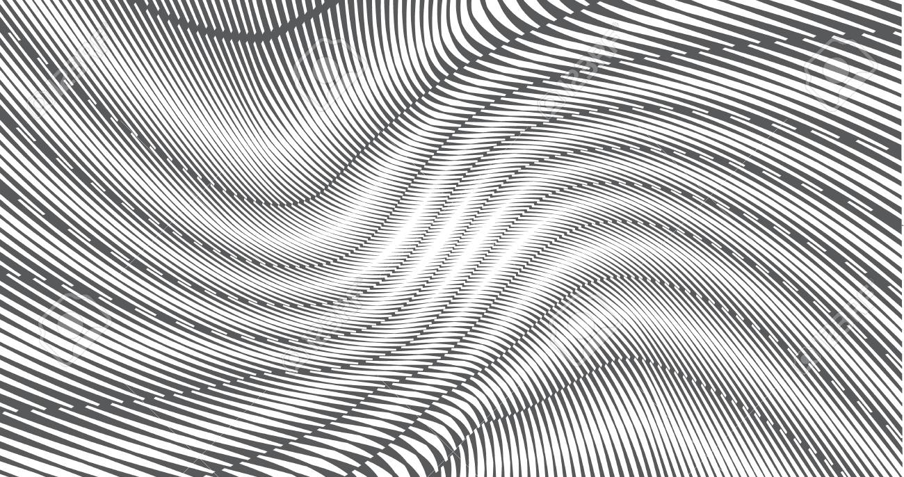
The Moire Effect refers to a pattern that is created in images occasionally. A moire pattern is a large in magnitude interference pattern. This can be produced with an opaque pattern that has transparent gaps overlaid within it. To see a large display of the moire interference pattern, two patterns cannot be identical in nature. The patterns have to be rotated or have a slightly different pitch. Overall it is a pretty trippy visual and it messes with our typical human perception in a variety of ways.

Moire Effect 3D Printing

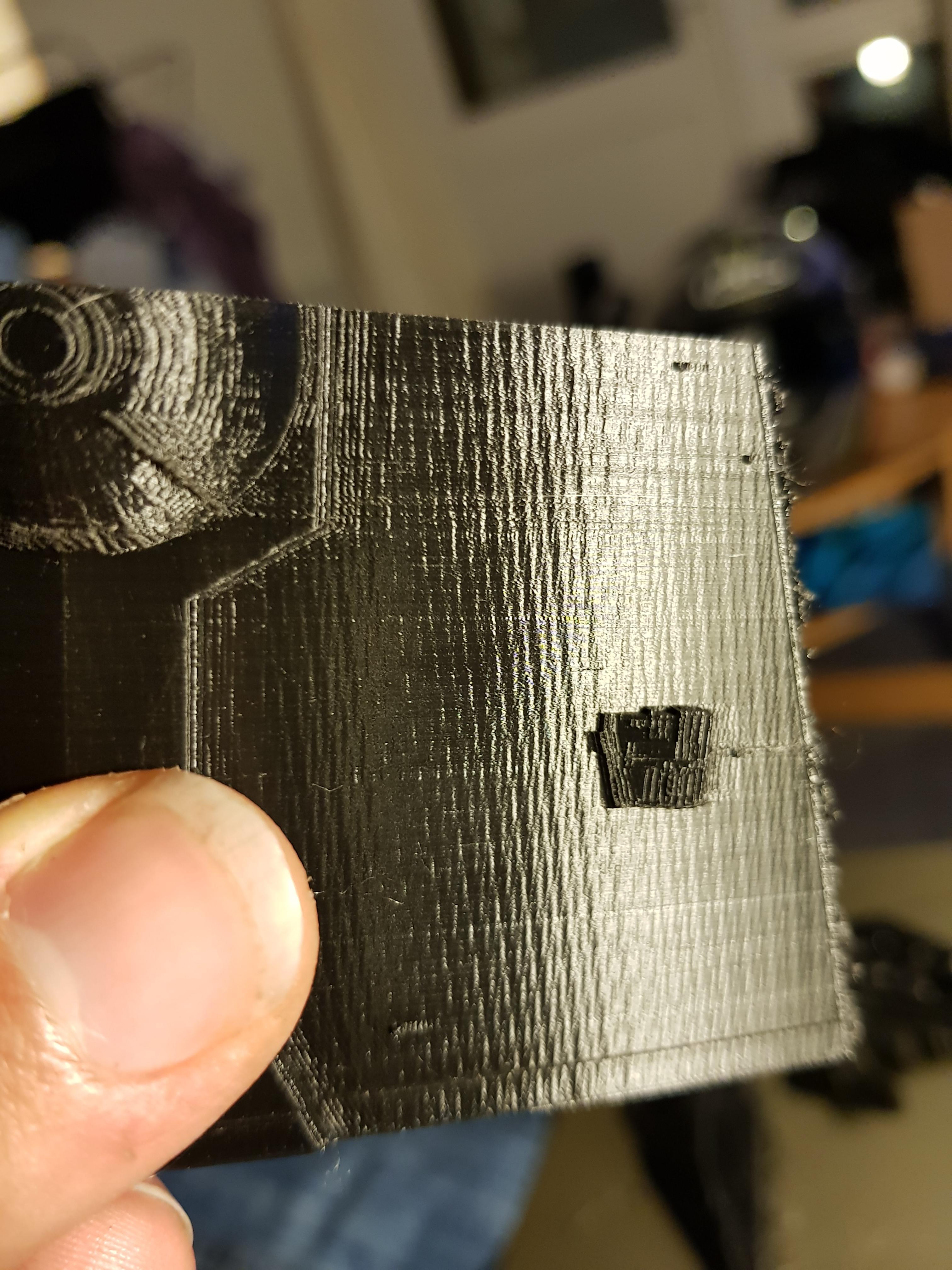
Constructing 3D images from 2D images is a difficult problem. An object that is 3D scanned is vulnerable to the moire effect. When doing a 3D print, the moire effect arises when you notice zebra like stripes on the surface of a print. To stop this it is critical to have great image processing on the 2D level. It seems as though it is nearly impossible to make a roughly perfect 3D image because of the impossibility of creating a perfect 2D image. This is okay, but we are still trying to attain the highest precision possible.

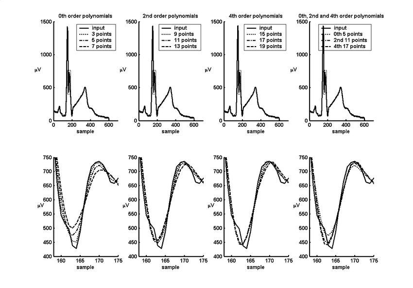
There is a lot of interesting math behind this effect as well. The essence of the moiré effect is the (mainly visual) perception of a distinctly different third pattern which is caused by inexact superimposition of two similar patterns. The mathematical representation of these patterns is not trivially obtained and can seem somewhat arbitrary. In this section we shall give a mathematical example of two parallel patterns whose superimposition forms a moiré pattern, and show one way (of many possible ways) these patterns and the moiré effect can be rendered mathematically.

{displaystyle {begin{aligned}f_{1}&={frac {1+sin(k_{1}x)}{2}}\[4pt]f_{2}&={frac {1+sin(k_{2}x)}{2}}end{aligned}}}

Moire Effect Mathematics

The visibility of these patterns is dependent on the medium or substrate in which they appear, and these may be opaque (as for example on paper) or transparent (as for example in plastic film). For purposes of discussion we shall assume the two primary patterns are each printed in greyscale ink on a white sheet, where the opacity (e.g., shade of grey) of the “printed” part is given by a value between 0 (white) and 1 (black) inclusive, with 1/2 representing neutral grey. Any value less than 0 or greater than 1 using this grey scale is essentially “unprintable”.

Moire Effect Background

When is the Moire Effect most prevalent? A terminology that is important to understand within metrology is strain measurement. Strain is a measure of the deformation of a body due to a force being applied to it. Strain is also the mathematical change in dimension of a body when a force is applied. Thus, strain measurement is focused on document the changes within dimension based on force applications. This is great when we want to measure deformations, but not for when we want to remove the possibility of them occurring through a 3D print. There are image scanners that have a descreen filter. These filters typically remove Moire-pattern artifacts. These are produced when scanning halftone images to produce digital images.

In conclusion, the Moire Effect as an interesting visual effect that occurs within the 2D realm and it readily affects the 3D world. With metrology technology, it is one of the various phenomena that can interfere with a high precision scan of an object.


The post What is Metrology Part 19 – Moire Effect in 3D Printing appeared first on 3DPrint.com | The Voice of 3D Printing / Additive Manufacturing.

What is Metrology Part 15: Inverse Filtering

Signal Processing

Signal processing is the name of the game that must be played in order to do image processing. Image processing is such a fascinating subject that I am excited to expand upon it.  It has amazing cross sectionality within various fields such as metrology, 3D printing, biomedical industries, and any industry that uses imaging as its main technology. Today we will be taking a look into inverse filtering as a specific method within signal processing. Signal processing is a general domain of expertise that can be applied in different settings. For the purposes of where we are in our metrology series, we will only focus on image processing.

imagerestoration.gif

Inverse Filtering

Inverse filtering is a method from standard signal processing. For a filter g, an inverse filter h is one that where the sequence of applying g then h to a signal results in the original signal. Software or electronic inverse filters are often used to compensate for the effect of unwanted environmental filtering of signals. Within inverse filtering there is typically two methodologies or approaches taken: thresholding and iterative methods. The point of this method is to essentially correct an image through a two way filter method. Hypothetically if an image is perfect, there will be no visible difference. The filters applied will correct a majority of errors within an image.

When we know of or have the skill to create a good model for a blurring function of an image, it is best to use inverse filtering. This is because having a model, or let’s say algorithm, allows us to efficiently and succinctly apply mathematical constraints to data in an instantaneous manner. The inverse filter is typically a high pass filter. 

ECG high-pass filter

A high-pass filter (HPF) is an electronic filter that passes signals with a frequency higher than a certain cutoff frequency and attenuates signals with frequencies lower than the cutoff frequency. In physics, attenuation is the continuous loss of flux intensity through an object. Flux is a rate of flow through a surface or substance in physics. For instance, dark glasses attenuate sunlight, lead attenuates X-rays, and water and air attenuate both light and sound at variable attenuation rates. The amount of attenuation for each frequency depends on the filter design. A high-pass filter is usually modeled as a linear time-invariant system. It is sometimes called a low-cut filter or bass-cut filter. If the cutoff frequency is lower than the cutoff frequency, our image will not allow for certain features to be shown in the next image transformation. This efficient method is great for low frequency signals, but the world and image data is not low frequency.  The outputs from the world are typically noisy. The linear time-invariant system of a high pass filter is needed in order to constrain the outputs one receives from the universe. When time is added as a variable for a signal, wild things can happen in terms of frequency. In order to conduct an inverse filter we have two techniques: thresholding and the iterative procedure. 

Thresholding

The word threshold can be defined as a level, point, or value above which something is true or will take place and below which it is not or will not. Thresholding in image processing refers to setting a value limit on the pixel intensity of an image. This threshold can be thought of in terms of our earlier discussion on filters. The image processing method is able to create a binary image. This technique is usually applied to grayscale images, but it can be applied to color images as well. We are able to dictate the level of intensity that we want to have our transformed image at. Pixels that are below this value are converted to black – this is the value of zero in binary code. Pixels above the threshold value are then converted to white – this is the value of one in binary code. 

The iterative method within inverse filtering is more of a mathematical guess and check solution. The goal is to guess what the original image was in terms of image processing.  With each mathematical guess, a user is able to build a better fitting model to represent a digital image. This method is more of a brute force algorithm method. This method is not as efficient as the thresholding method, but it does have the advantage of better stability when dealing with noise. We do not need to be time invariant when dealing with this method. 

Overall, this is only one of the many examples of image processing techniques. As a follow up to this article, I will do some interactive code and I’ll showcase some of the power of these methods when we are taking a look at these problems through the lens of computer science and engineering.

The post What is Metrology Part 15: Inverse Filtering appeared first on 3DPrint.com | The Voice of 3D Printing / Additive Manufacturing.

#3DPrint a 58mm Solar Filter #celebratephotography

NewImage

From madhead_ on Instructables:

Neat solar filter for telephoto DSLR lenses. IMHO, looks far better than cardboard crafts.

Read more


Photofooter

We #celebratephotography here at Adafruit every Saturday. From photographers of all levels to projects you have made or those that inspire you to make, we’re on it! Got a tip? Well, send it in!

If you’re interested in making your own project and need some gear, we’ve got you covered. Be sure to check out our Raspberry Pi accessories and our DIY cameras.