
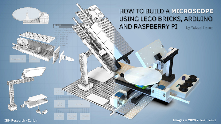
I always enjoy a good 3D printed DIY project, whether it’s truly helpful or just for fun. These projects are even cooler when you add Legos into the mix, like Reddit user DIY_Maxwell did. He posted about his work using 3D printing, Arduino, Raspberry Pi, and Lego bricks to make an open source, motorized microscope. But, the microscope itself is not fully 3D printed – instead, the body was built with Lego bricks and some 3D printed components. What makes this project more awesome is the stop motion-style video he made showing the various parts of the project and how they all fit together to make a working microscope.
BUILD YOUR OWN MOTORIZED MICROSCOPE using 3D-printing, Lego bricks, Arduino and Raspberry Pi… all design files, source codes and detailed instructions are provided open-source. from r/3Dprinting
“I wanted to have a modular microscope, something I can easily modify for transmitted-light, reflected-light, cross-section, etc. My early prototypes did not have Legos, as I started making my own interlocking pieces, I realized that I was in fact printing lego-like designs, I thought buying legos would be less of an effort,” he wrote on Reddit when asked why he didn’t 3D print all the parts. “Then I found out about these “sliding” lego pieces, which are very precise for linear actuators. The other advantage is that, if I want to change the height of the camera let’s say, I simply add more bricks, it’s convenient.”

DIY_maxwell used FreeCAD to design the 3D printed microscope parts, which were fabricated on an Ender 3 system. All of the source codes and design files have been provided open source on GitHub, along with detailed step-by-step instructions on how to make your own.
Before you jump right in, do you know what exactly a motorized microscope does when compared to a regular microscope? DIY_maxwell explained that, at least for him, it needed to be able to tilt in order to take photos, from an angle, of “highly reflective surfaces (semiconductor chips),” and that it should quickly adjust the focus and magnification, and position of the sample.
“The microscope has a simple operation principle based on changing the magnification and the focus by adjusting the relative distances between a camera, a single objective lens and a sample. Briefly, two linear stages with stepper motors are used to adjust these distances for a continuous and wide magnification range,” the GitHub instructions state. “Four additional stepper motors tilt the camera module and change the X-Y position and rotation of the sample. A uniform light source illuminates the sample either from an angle (reflected light) or from the bottom of the sample (transmitted light).”
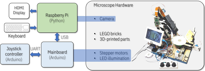
The main components of this modular, motorized microscope include a Raspberry Pi system, an 8 MegaPixel camera, six stepper motors, a keyboard or joystick for variable speed control, uniform illumination, and obviously plenty of Lego bricks. Depending on the specific features and electronics vendors used, the whole thing costs between $200-$400, and once you have all the parts in front of you, should only take a couple of hours to assemble.
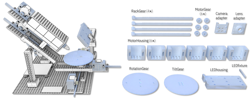
The main body was built with individually-purchased Lego bricks, and DIY_maxwell designed custom actuators and 3D printed them, rather than using available motors and gears from LEGO Technic.
“This approach not only lowered the cost of the microscope but also gave me some flexibility in the design and implementation of precise linear and rotary actuators. In principle, the whole structure could be 3D-printed without using any LEGO parts but that would be less modular and more time consuming,” he writes in GitHub.
In addition, 3D printing offers you the flexibility of quickly changing the design for maximum optimization if and when it’s needed.
“If the parts do not match well, some minor modification in the original design file (e.g. enlarging the holes matching to LEGO studs) or polishing/drilling may be required,” he explained.

The contents of the motorized microscope are as follows:
- Linear Actuators
- Camera Module
- Rotary Stage
- Illumination
- Tilt Mechanism
- Electronics
- Final Assembly
- Software
You can find detailed instructions, images, slicer settings, tips, and more on GitHub, and a longer version of the assembly video can be viewed here.
Several other Reddit users who routinely use microscopes related how impressed they were about the project; a geologist mentioned that “starting price can be anywhere between $500 to $1000 for something with that kind of quality” when DIY_maxwell said that his microscope could “easily resolve 10um features.” A pathologist expressed excitement about “a modular system to motorize common non motorized microscopes (Leica, Olympus, etc.).” While the compliment was appreciated by the maker, it was noted that “this microscope is not meant to replace a lab microscope used for medical assessment. No dark-field, no fluorescence, no aperture control, it suffers from chromatic aberration and other optical effects at high magnification, etc.”
“I hope this prototype persuades other DIY-enthusiasts to develop new designs of microscopes.”
If you’re interested in using 3D printing to make your own microscope, you can check out all of the relevant information on GitHub to build this one, or check out the OpenFlexture Microscope project on Wikifactory. This was created as “part of the Waterscope initiative, which by allowing for fast and affordable on-site bacterial testing of the water quality in developing regions of the world, is helping to cope with the diseases caused by bad quality water drinking.”

OpenFlexure Microscope
The OpenFlexure can be built in the classroom and used as an education tool for both students and teachers. Because the 3D printed microscope stage uses plastic flexures, the motion is free from friction and vibration, and the four-bar linkages in the stage can be 3D printed in a single job with no support material.
You can find other open source 3D printable microscopes on Thingiverse as well; happy making!
Discuss this and other 3D printing topics at 3DPrintBoard.com or share your thoughts below.
The post Build Your Own 3D Printed Open Source Motorized Microscope appeared first on 3DPrint.com | The Voice of 3D Printing / Additive Manufacturing.


