New Guide: Make Your Own Cosplay Fireball Props with Motion Sensing

Cosplay Fireball

Check out the latest tutorial from Erin St. Blaine: make a magical floating fireball prop for your Cosplay character. A snap of the wrist makes the LED flames flare up brightly! This is a fun beginner project, with no soldering required. The code is done in Microsoft MakeCode, with a drag-and-drop code block editor, so it’s easy to change colors or animation triggers.

From the guide:

Complete your cosplay with this Magical Item: a floating fireball that flares up at your command. Whether you’re portraying Kael’thas Sunstrider from WoW or trading flaming shots with Super Mario and Luigi, this fireball will push your outfit over the top. This is a very easy project, with no soldering required. The Circuit Playground board makes motion-sensing programmable lights a snap. Customize your colors and your animation speed with Microsoft MakeCode’s drag-and-drop code editor. You’ll be stopped for so many photos that you’ll never make it to that panel discussion at DragonCon.

Full tutorial: https://learn.adafruit.com/cosplay-fireball-prop-with-motion-sensing/

New Guide: Build a NeoPixel Crystal Chandelier with Speed & Brightness Control

DIY crystal chandelier

Take a look at the latest guide from Erin St. Blaine: build a three tiered chandelier with hanging DIY paper-craft crystals that light up with pixels inside. Easily add your own custom animations using CircuitPython and the LED Animations Library. This guide takes animated lights a step further, adding a rotary encoder knob that controls the brightness or the animation speed of the pixels, and also acts as an on/off switch. From the guide:

Floating crystals and glowing lights are a match made in heaven. This project combines a wide variety of skills and tools into one lovely project. Make a gorgeous hanging lamp with sparkly beads, glowing crystals, live edge wood and of course, lots of NeoPixels.

My chandelier is unique, and designed to show my personal style. Since you, dear reader, have your very own unique style, this tutorial will focus on giving you the tools to design and create your own one-of-a-kind bespoke hanging lamp. This tutorial will provide source files and ideas, and give guidance on how the electronics fit together.

This tutorial will also get you started with customizing your own software animations. The sample code uses CircuitPython and the delightfully easy to use LED Animations Library by Kattni Rembor. This code gives you a framework that allows speed and brightness control using a rotary encoder knob, so you can adjust the lighting to suit any environment or mood.

See the full build tutorial here: https://learn.adafruit.com/neopixel-crystal-chandelier-with-circuitpython-animations-and-speed-control/overview

crystal chandelier

We can’t wait to see the creative lamp you build with NeoPixels and Circuit Python!

3D Printed Plastic Geoboards Teach Visually Impaired Students about Geometry

Geometry is the branch of mathematics that relates to angles, geometric shapes, lines and line segments, and rays, and you use geometry concepts to measure lengths and areas of 2D shapes and calculate the volume and surface area of 3D shapes. I was never any good at geometry (or any mathematics, to be honest), so I can’t imagine how hard it must be to learn when you are visually impaired. Three researchers from Thailand wrote a paper, “The Designation of Geometry Teaching Tools for Visually-Impaired Students Using Plastic Geoboards Created by 3D Printing,” about making 3D printed teaching tools for visually impaired students – a concept we’ve seen before.

Visually impaired students must interpret 2D shapes through a sense of touch.

“There are several teaching tools available on the market that can serve this purpose effectively; however, the imported products are too expensive,” the researchers explained.

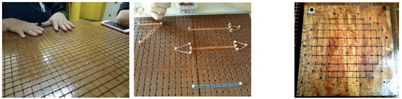
Traditional wooden geoboards.

A geoboard is a great way to teach visually impaired students geometry, as it helps them better understand geometric reasoning, terminology, and theorems. It’s a physical board with rivets half driven in, and rubber bands are wrapped around the nails to teach plane geometry concepts and polygons.

“According to the difficulty of wooden geoboard making and carrying, we propose to replace the existing model with the unlimited design of light and colorful geoboards,” the team wrote.

Using 3D printing to make lightweight geoboards out of plastic costs less money, and they can be customized to fit user requirements. The researchers created colorful geoboards to teach visually impaired elementary students in Bangkok about angles, circle components, line segments, shape areas, and 3D geometric shapes, like prisms and cubes. They also made additional teaching tools, like arrowheads, protractors, and 3D object models, for lessons about 2D and 3D shapes and geometry.

The SketchUp model and 3D printing of geoboards.

SketchUp was used to create the colorful 20 x 20 cm geoboards, which were printed out of PLA on a Flashforge Creator Pro over 18 hours. Two patterns were made – a 10 x 10 grid on the x-axis and y-axis with a square edge, and a 4-quadrant graph with a circular edge and 24 circumference scales. Braille scales are included so the students can identify 0-10 on the x and y axes, and the top right corner of the boards have two columns of three dots to show that they’re upright.

“Z-axis pillars with different heights, identified by braille, were also created for 3D geometry teaching,” the team explained.

“There were 24 points identified by the letters A to Y on the circumference with a 15-degree angle difference for teaching about circles and tangents. The central point was identified by the letter O and the circle diameter was 13 cm. Raised grid lines 1.5 mm in height were also generated for exploring direction by blind touch.”

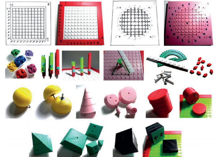
Plastic geoboards with square and circle edges, learning accessories, and segments of 3D objects for spheres, cones, cylinders, pyramids, and cubes.

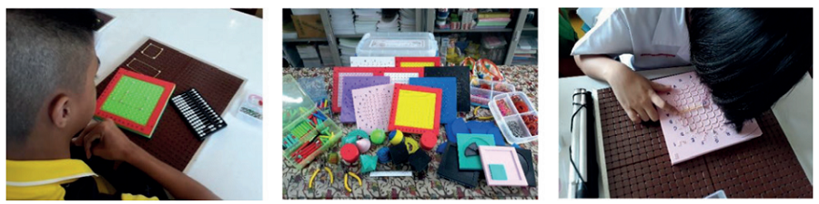
15 visually impaired fourth graders and three experienced teachers participated. The experimental group and the control group each completed 15 one-hour periods of different learning activities. After a pre-test, the control group continued with traditional geoboards, while the experimental group switched to the 3D printed ones.  You can see teaching and assessment contents with related exercises for the experimental group in a portion of Table 1 below.

“The coordinate points of 2D geometry were explored by blind touch on braille scales and raised grid lines, while z-axis pillars were used for 3D geometry by connecting rubber bands to the plane,” the researchers explained.

The students in the experimental group used the 3D printed geoboards to learn about 2D geometry. For example, they stretched rubber bands across rivets on the square board, connecting two points to draw a straight line and “an angle of 2 lines from 3 points on the coordinate plane.” To learn about straight and parallel lines, rays, and right, acute, and obtuse angles, arrowheads could be attached to the ends of the lines.

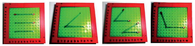
Teaching about straight lines, parallel lines, rays, and angles.

They used the circular geoboard for learning angle measurements and circle components, like radius and diameter, and 2D geometric shapes, like squares and triangles.

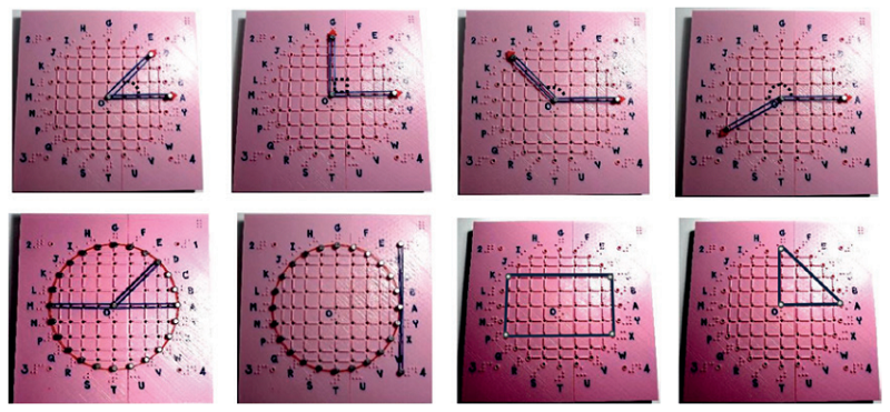
Teaching about angles, circle components, squares and triangles.

The geoboards were also used to teach 3D geometry with plastic pillars on the z-axis. Once the students had the basic concept down, pillars on this axis “with different heights of 4, 5 and 6 units can be used to teach 3D geometric shapes and volumes.” Multiple pillars were used to create prism, and pyramids with differently-shaped bases.

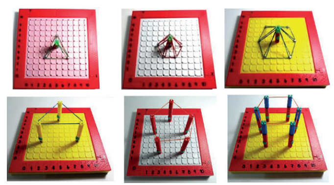
Teaching to create 3D geometric shapes for pyramids and prisms, similar to 3D object models.

“The raised grid lines with braille numbering are handy for identifying shape locations, measuring distance, and calculating areas or perimeters; and scales can be applied for measuring the diameter or radius of a circle on a cylinder, cone, or sphere and multiplying the area by the height to find the volume,” they wrote.

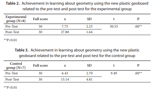
At the end, both student groups took another test, and independent two-sample t-tests were used to analyze and compare the differences in the mean scores of the pre-test and post-tests between the groups. You can see the mean scores (x) and standard deviations (SD) for the tests below.

The participants also completed a questionnaire, using a 5-point Likert scale, about how satisfied they were with the 3D printed geoboards. They evaluated the quality of the teaching tools and the benefits of the learning activities, and answered open-ended questions regarding areas for improvement and their personal opinions.

“The response showed that the new geoboards as a teaching tool were considered to be much more satisfactory than the traditional tool because the mean scores were very high (>4.8) in all areas,” the researchers noted.

All the participants agreed that the 3D printed geoboards made class more enjoyable for the visually-impaired students, and that they “enhanced the mental imagery and understanding of geometry.”

“The prototype testing showed that the experimental group had a higher mean score on the post-test than did the control group, indicating that the learning achievement of the visually-impaired students who learn with the new geoboards is significantly higher than that of the students who learn with the regular tools. The participants’ satisfaction with the geoboards in terms of learning about geometry was evaluated highly on the part of the teachers and the students because the tangible teaching tools were considered more effective for understanding geometry with good visual imagery than when using the traditional tools,” the team concluded.

Discuss this and other 3D printing topics at 3DPrintBoard.com or share your thoughts below.

The post 3D Printed Plastic Geoboards Teach Visually Impaired Students about Geometry appeared first on 3DPrint.com | The Voice of 3D Printing / Additive Manufacturing.

Make All the Things Part 2: Ring Creation and Casting a Wax Ring, Part 2

This is the final installation of the wax ring project I have been working on. It has been such a great learning experience, and it has invigorated the maker within me. I highly suggest everyone to start making projects for fun. There is such a cathartic feeling attached with having an idea and bringing it to completion. It really pushes oneself to get things done. The creativity and new skill sets associated with building projects is so rewarding. Before this project I had zero skills in jewelry making and prototyping. After this project, I will not be at the level of a professional jeweler, but I have a newfound confidence to experiment and make new jewelry projects in my spare time. I also see what areas I need to improve to be a better designer. I will definitely be working and crafting my 3D design skills if I want to make very intricate designs for the future.

Before Cleaning Up

The end of this project required a good amount of clean up of our rings. Buffing, cutting, as well as sanding was necessary to complete the project. The ring was still attached to our sprue structure that was discussed in our previous articles. In order to remove this,  we first needed large bolt cutters to clip the base material of the structure. This requires one to place the structure on the floor and then use force to cut the base. I had to put on a mask for facial safety in case of debri flying from the ground towards my eyes. After this has been cut, the tree like structure can then be cut further with different tools. The main tools used for this include a jeweler’s blade as well as pliers. The pliers were used to remove the stems of sprues within the structure.  It takes a bit of dexterity as well as patience to make sure that the structure is properly handled. 

Rotary Dentist Tool

The biggest issue from this is making sure that the cuts and blade movement are precise. A jeweler’s blade is very thin. This can lead to the blade breaking easily during a cut if one is not precise in their movement. One does not want to have chunks of material still hanging off their piece also. This will make the next step of the process way more difficult than we would want. I learned this through firsthand experience. The next step in the process was focusing on grinding the extra chunks of material within the ring. The pliers did an okay job of removing the stems within our sprue structure, but nubs of the material were still present. I then used a handy set of dentist tools to grind the inside of my rings. Before this project, I had no idea how the dentistry industry and the jewelry industry used similar tools. With the rotary grinder tool available to me, I then smoothed out the inside of the ring as best as I could. Honestly, my precision and detail were only okay. It is definitely a great start in the journey of refinement and detail. I would say that I miss out on details at times, and I believe keeping up with this hobby of jewelry will really develop my attention to detail.

Jeweler’s Blade

Once these nubs of material were ground out with the dentistry tools, I focused on finishing the product in terms of refinement. This is where sanding precision came into play. I took an 80 grit piece of sandpaper and applied it to the perimeter of the rings. This helped to bring out the true shine of silver in the designs. This part of the process was simple, but the most difficult part was to come. I had to sand done the face of the lion without degrading the actual design of the ring. This requires using the rotary dentist tool again. It took some precision, but the lion head was buffed and the silver shine of the material came through all around the ring. 

Finished Product

With this done, I finally had a cool lion ring made. The overall cost of the project itself in terms of silver was $200. With a bit more refinement, I will be able to sell this product at a high price point. Some follow ups of this project would include building a mold of the ring. This would then cut down the time associated with creating this product. Thank you all for watching this project evolved, but be prepared for new projects that I have ready for the future.

The post Make All the Things Part 2: Ring Creation and Casting a Wax Ring, Part 2 appeared first on 3DPrint.com | The Voice of 3D Printing / Additive Manufacturing.

New Guide: Paper Craft Crystal Gems Tutorial #cosplay #stevenuniverse

New tutorial from Erin St. Blaine: create amazing cosplay glowing crystal gems!  From the guide:

Crystal Gems will always save the day!

Create a stunning paper craft crystal from laminated cellophane wrap. Add NeoPixels and watch it sparkle!

We’ve included two different build sizes in this tutorial — one crystal large enough to house a Circuit Playground Express, and one with a single NeoPixel illuminating the crystal. This project can be run from a battery for cosplay applications (the crystal on Gandalf’s staff perhaps?) or plugged in to the wall via USB for a more permanent installation.

We’ve also included a Steven Universe Warp-Pad 3D printable base, so your Crystal Gems can be displayed in style. The possibilities are endless!

We love these gems. They’re easy to make with a few easily found tools. The main ingredient is cellophane gift wrap that’s been run through a laminating machine, which creates a perfect material for paper crafting — stiff enough to hold up but easy to cut with scissors or a utility knife. You can also get fancy and use a vinyl cutting machine to create perfect gems in multiple sizes. 3d print a base, or use the gem in a hanging lamp, or place it on top of your staff for a Gandalf-style cosplay. Such a cool project!

Full tutorial: https://learn.adafruit.com/paper-craft-crystal-gem-lantern

3D Printing News Briefs: March 1, 2019

On this first day in March, we’re sharing business and dental news with you. Markforged is helping businesses speed up and facilitate their 3D printing adoption with its new Additive Manufacturing University, and 3DEO is more than doubling its production capacity this quarter. Lumi Industries has entered into a distribution agreement with Harzlabs for 3D printing dental resins, and Renishaw is leveraging Polygonica for its dental applications.

Markforged Announces Additive Manufacturing University

Boston 3D printer company Markforged announced a new program this week that’s meant to help large manufacturing businesses facilitate and accelerate their 3D printing adoption. Its Additive Manufacturing University was built to help companies learn some of the skills they’ll need to design for additive manufacturing, manage the 3D printing process, find new applications for the technology, and successfully build businesses cases for replacing the lengthy, expensive manufacturing processes traditionally used with 3D printing. There are three main ways for companies to take advantage of the Markforged Additive Manufacturing University: onsite at Markforged for single or multi-day workshops; certification and training delivered at a customer’s own facility; and the free, on-demand Markforged Learning Library.

“Markforged Additive Manufacturing University is really about inspiring industry-wide innovation. Once we’ve helped engineers, designers, and the manufacturing industry build a strong foundation of additive manufacturing skills, the potential is nearly limitless,” said Andrew de Geofroy, the Markforged Vice President  of Application Engineering.

3DEO Continues Its Growth in 2019

Metal 3D printing company 3DEO, Inc., based in Los Angeles and founded in 2016, grew a lot last year, having used its patented Intelligent Layering Technology to 3D print and ship over 30,000 paid parts to customers in multiple industries in 2018. It appears that this growth isn’t slowing down either, as the company is more than doubling its production capacity this quarter to meet customer demand with its proprietary metal 3D printers. It’s only the first day of March, and 3DEO has already locked down two more customer production orders that are scheduled for delivery this year, one for 24,000 pieces and another for 28,000.

By all measures, 3DEO is rapidly expanding to fill a large void in the market of small complex metal parts. Customers are validating our technology across a variety of industries and we are either in production or quickly moving to production with many clients,” said Matt Petros, CEO and Co-Founder of 3DEO. “Additive manufacturing is finally competing directly with traditional manufacturing, enabling significant volumes to shift over to AM. It is a very exciting time for 3DEO, metal additive manufacturing and our customers.”

Lumi Industries and Harzlabs Announces Dental Distribution Agreement

Russian startup HARZLabs, which manufactures resins, recently had a successful European launch at formnext 2018. The company keeps environmental protection in work spaces and the healthcare of operators at the forefront by using high quality raw materials that they say give their 3D printing resins a low rate of toxicity, with hardly any odor. This means they claim that they can be used safely in naturally ventilated laboratories, without requiring a dedicated evacuation system.

Now, Italian DLP 3D printing company Lumi Industries has entered into a distribution agreement with HARZLabs for its professional dental resins, and will be distributing the materials at a competitive price through its online store in 1 or ½ kilo leak-proof sealed bottles. The line of 3D printing dental resins is currently under certification, and includes Dental Cast, heat resistant Dental Yellow Clear, transparent and low-viscosity Dental Clear, and Dental Sand A1-A2, which is perfect for highly detailed prints.

Renishaw Leveraging Polygonica for Dental 3D Printing

3D printing company Renishaw manufactures advanced 3D printers and software, but it also produces crowns and bridges through its dental services business. Renishaw leverages mesh processing software Polygonica to enable more reliable automation for this particular application, which used to be completed with lost wax casting and CNC milling processes. David Turner, Renishaw’s Software Development Manager, explained that the company runs into mesh integrity issues with small holes and gaps, non-manifold bodies, floating shells and voids, and incorrectly oriented triangles.

“The amount of mesh detail is really key to us because we’ve got tens of thousands of parts coming in monthly. That takes up a lot of server space plus the amount of bandwidth it takes to shift these parts around our manufacturing system is huge. Also, the amount of time to process those parts and create laser paths that we can actually then build the parts with goes up massively,” Turner said.

“Polygonica helps us reduce the amount of data in the mesh whilst guaranteeing not to lose important detail.”

Turner also said that Renishaw uses Polygonica to help with other mesh modeling needs, such as product identification and tracking, creating nesting algorithms, hub placement, and creating abutments. Renishaw also used Polygonica to develop its ADEPT craniomaxillofacial design tool for 3D printing, which you can learn more about in the following video:

Discuss these stories and other 3D printing topics at 3DPrintBoard.com or share your thoughts in the Facebook comments below.

New Project! Desktop Rack and Pinion Mechanism with CRICKIT #3DPrinting #Robotics #Adafruit

Now on the Adafruit Learning System:

Rack and Pinion Bot

Learn how to create an automated geared mechanism with hypnotic motion. Use the Adafruit CRICKIT and Circuit Playground Express to make it dance! This is a mechanism for converting rotary motion to linear oscillating motion. The gear appears to bounce back and forth as it continuously rotates. As the wheel spins, the gear turns and oscillates between two tracks. It emits clacks and sloshes sound while in motion creating the sense of white noise. The teeth engage the lower track as it rotates. When it has travels the length of the slot, the teeth clears the end of the track and catches the teeth in the upper part of the track.