3D Printing in Ophthalmology: Smartphone Slit-Lamp Adapter for Diagnostics

A trio of researchers from hospitals in Egypt and India recently published a paper, titled “Custom-made three-dimensional-printed adapter for smartphone slit-lamp photography,” about their work designing a custom 3D printed smartphone slit-lamp adapter for photography applications in ophthalmology. A slit-lamp consists of a high-intensity light source, used with a biomicroscope, that can be focused to shine light into the eye for examination of the anterior and posterior segments in order to diagnose many conditions, like macular degeneration, cataracts, corneal injuries, and a detached retina.

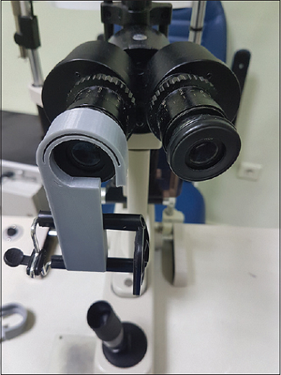
3D printed adapter fixed on eyepiece to refine the sizing.

Many people have smartphones these days, and they are being paired more often with 3D printing for diagnostic and imaging purposes, especially in the offices of eye doctors.

“Smartphone photography in ophthalmology has a wide variety of uses including examination with or without other examination tools such as slit lamp or condensing lenses,” the researchers wrote. “Smartphones can be used for fundus photography,[2],[3],[4] slit-lamp photography,[5] microscope-free anterior segment photography,[6] gonioscopy,[7] and more.[5]

3D printed adapters can help make these tasks more efficient, as they are a quick, low-cost option. Custom adapters are built for just one smartphone design and slit lamp, while universal adapters can be adjusted to fit many designs. There are pros and cons for each option, which is why these researchers chose to “combine the advantages of both approaches” for their 3D printed smartphone slit-lamp adapter.

Two copies of the blink 3D printed slit-lamp adapter (in gray and black ABS material) fixed to universal smartphone holders.

“It is built upon a commercially available part used in selfie sticks and tripods which is used to hold the phone,” they explained. “The rest of the adapter is designed and 3D printed to enable attaching the mobile with that holder to the selected eyepiece.”

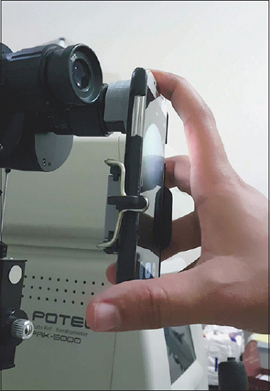
Smartphone fixed on the Blink adapter and placed on slit-lamp eyepiece.

The goal was to make a design that complements different slit-lamps and automatically fits the microscope eyepiece that slides into the adapter; gravity, plus the weight of the smartphone, will keep it in place.  Then all of you have to do is place the phone’s camera against the eyepiece. The team named their creation Blink, for its “ease of use and quick adjustment like in a blink of an eye.”

After they chose their target slit-lamp microscope, the researchers used Vernier calipers to measure the eyepiece, and used the dimensions to create a CAD model of the adapter in Tinkercad. They refined the model using SketchUp, and prepared it for printing with Repetier software. The adapter was then 3D printed out of ABS material on a Rostock MAX v2 3D printer from SeeMeCNC.

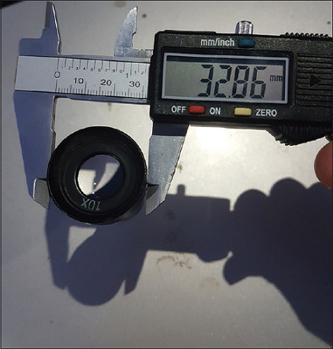
Measurements of slit-lamp eyepiece being taken with digital Vernier calipers.

The 3D printed adapter was then fixed to the universal smartphone holder, and finally the fitting was “tested and refined to account for manufacturing tolerances.” Once the smartphone was placed in the holder, the device was attached to the slit-lamp’s eyepiece for easy imaging.

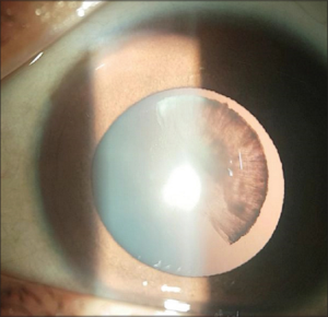
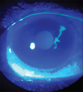
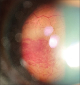
“The blink 3D-printed smartphone slit-lamp adapter was successfully designed, modeled, 3D-printed, and tested,” the researchers wrote. “Each type of slit-lamp eyepiece required a small modification in the 3D design based on measurements. Good-quality images could be captured in diffuse, slit, retro, and cobalt-blue illumination.”

The time it took to remove and modify the device was only seconds, which makes the 3D printed adapter very useful in slit-lamp photography.


“More units can be easily made by printing the same CAD file and fixing it to the universal smartphone holding bracket,” the researchers noted.


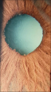
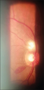
Additionally, the team confirmed that they could image the fundus – the part of the eyeball opposite the pupil – using a 90D lens.


“Our article describes the process of designing and building a smartphone slit-lamp adapter to solve the problem of slit-lamp photography,” the researchers concluded. “The cost of 3D printing a small part such as the adapter described here is small and can be done at a 3D printing shop which is available in all major cities in India, Egypt, and many other countries. Most of the work involved is in designing the CAD model according to measurements and physical constraints.

“Development of this type of innovation from idea to virtual design to hardware does not need much time or money – only an innovative mind and the drive to learn these new techniques.”

Discuss this story and other 3D printing topics at 3DPrintBoard.com or share your thoughts in the Facebook comments below.

The post 3D Printing in Ophthalmology: Smartphone Slit-Lamp Adapter for Diagnostics appeared first on 3DPrint.com | The Voice of 3D Printing / Additive Manufacturing.

Build Your Own 3D Printed Open Source Motorized Microscope

I always enjoy a good 3D printed DIY project, whether it’s truly helpful or just for fun. These projects are even cooler when you add Legos into the mix, like Reddit user DIY_Maxwell did. He posted about his work using 3D printing, Arduino, Raspberry Pi, and Lego bricks to make an open source, motorized microscope. But, the microscope itself is not fully 3D printed – instead, the body was built with Lego bricks and some 3D printed components. What makes this project more awesome is the stop motion-style video he made showing the various parts of the project and how they all fit together to make a working microscope.

BUILD YOUR OWN MOTORIZED MICROSCOPE using 3D-printing, Lego bricks, Arduino and Raspberry Pi… all design files, source codes and detailed instructions are provided open-source. from r/3Dprinting

“I wanted to have a modular microscope, something I can easily modify for transmitted-light, reflected-light, cross-section, etc. My early prototypes did not have Legos, as I started making my own interlocking pieces, I realized that I was in fact printing lego-like designs, I thought buying legos would be less of an effort,” he wrote on Reddit when asked why he didn’t 3D print all the parts. “Then I found out about these “sliding” lego pieces, which are very precise for linear actuators. The other advantage is that, if I want to change the height of the camera let’s say, I simply add more bricks, it’s convenient.”

DIY_maxwell used FreeCAD to design the 3D printed microscope parts, which were fabricated on an Ender 3 system. All of the source codes and design files have been provided open source on GitHub, along with detailed step-by-step instructions on how to make your own.

Before you jump right in, do you know what exactly a motorized microscope does when compared to a regular microscope? DIY_maxwell explained that, at least for him, it needed to be able to tilt in order to take photos, from an angle, of “highly reflective surfaces (semiconductor chips),” and that it should quickly adjust the focus and magnification, and position of the sample.

“The microscope has a simple operation principle based on changing the magnification and the focus by adjusting the relative distances between a camera, a single objective lens and a sample. Briefly, two linear stages with stepper motors are used to adjust these distances for a continuous and wide magnification range,” the GitHub instructions state. “Four additional stepper motors tilt the camera module and change the X-Y position and rotation of the sample. A uniform light source illuminates the sample either from an angle (reflected light) or from the bottom of the sample (transmitted light).”

The main components of this modular, motorized microscope include a Raspberry Pi system, an 8 MegaPixel camera, six stepper motors, a keyboard or joystick for variable speed control, uniform illumination, and obviously plenty of Lego bricks. Depending on the specific features and electronics vendors used, the whole thing costs between $200-$400, and once you have all the parts in front of you, should only take a couple of hours to assemble.

The main body was built with individually-purchased Lego bricks, and DIY_maxwell designed custom actuators and 3D printed them, rather than using available motors and gears from LEGO Technic.

“This approach not only lowered the cost of the microscope but also gave me some flexibility in the design and implementation of precise linear and rotary actuators. In principle, the whole structure could be 3D-printed without using any LEGO parts but that would be less modular and more time consuming,” he writes in GitHub.

In addition, 3D printing offers you the flexibility of quickly changing the design for maximum optimization if and when it’s needed.

“If the parts do not match well, some minor modification in the original design file (e.g. enlarging the holes matching to LEGO studs) or polishing/drilling may be required,” he explained.

The contents of the motorized microscope are as follows:

  • Linear Actuators
  • Camera Module
  • Rotary Stage
  • Illumination
  • Tilt Mechanism
  • Electronics
  • Final Assembly
  • Software

You can find detailed instructions, images, slicer settings, tips, and more on GitHub, and a longer version of the assembly video can be viewed here.

Several other Reddit users who routinely use microscopes related how impressed they were about the project; a geologist mentioned that “starting price can be anywhere between $500 to $1000 for something with that kind of quality” when DIY_maxwell said that his microscope could “easily resolve 10um features.” A pathologist expressed excitement about “a modular system to motorize common non motorized microscopes (Leica, Olympus, etc.).” While the compliment was appreciated by the maker, it was noted that “this microscope is not meant to replace a lab microscope used for medical assessment. No dark-field, no fluorescence, no aperture control, it suffers from chromatic aberration and other optical effects at high magnification, etc.”

“I hope this prototype persuades other DIY-enthusiasts to develop new designs of microscopes.”

If you’re interested in using 3D printing to make your own microscope, you can check out all of the relevant information on GitHub to build this one, or check out the OpenFlexture Microscope project on Wikifactory. This was created as “part of the Waterscope initiative, which by allowing for fast and affordable on-site bacterial testing of the water quality in developing regions of the world, is helping to cope with the diseases caused by bad quality water drinking.”

OpenFlexure Microscope

The OpenFlexure can be built in the classroom and used as an education tool for both students and teachers. Because the 3D printed microscope stage uses plastic flexures, the motion is free from friction and vibration, and the four-bar linkages in the stage can be 3D printed in a single job with no support material.

You can find other open source 3D printable microscopes on Thingiverse as well; happy making!

Discuss this and other 3D printing topics at 3DPrintBoard.com or share your thoughts below.

The post Build Your Own 3D Printed Open Source Motorized Microscope appeared first on 3DPrint.com | The Voice of 3D Printing / Additive Manufacturing.

A Google Pixel 3a microscope adapter #Photography #3Dprinting

Ed Nisley posts about building yet another camera adapter, this time for a microscope eyepiece.

Hand-holding my Google Pixel 3a phone over the microscope eyepiece worked well enough to justify building Yet Another Camera Adapter:

Pixel 3a Microscope Adapter - in action

The snout is a loose fit around the 5× widefield microscope eyepiece, with the difference made up in a wrap of black tape; it’s much easier to adjust the fit upward than to bore out the snout. An overwrap of tape secures the snout to the eyepiece, which I’ve dedicated to the cause; the scope normally rocks 10× widefield glass.

The tapered hole exposes the phone’s fingerprint reader to simplify unlocking, should it shut down while I’m fiddling with something else.

The microscope doesn’t fully illuminate the camera’s entrance pupil at minimum zoom, with 4.5× filling the screen and (mostly) eliminating the vignette. The corner blocks have oversize holes to allow aligning the camera lens axis over the microscope optical axis. The solid model incorporates Lessons Learned from the version you see here, because you (well, I) can’t measure the camera axis with respect to the outside dimensions accurately enough.

See the post for details.

Pixel 3a Microscope Adapter - test image - max mag