Researchers from Nanyang Technological University in Singapore wrote a paper, titled “Development of a Robotic System for Automated Decaking of 3D-Printed Parts,” about their work attempting to circumvent a significant bottleneck in 3D print post-processing. In powder bed AM processes, like HP’s Multi Jet Fusion (MJF), decaking consists of removing residual powder that sticks to the part once removed. This is mostly completed by human operators using brushes, and for AM technologies that can produce hundreds of parts in one batch, this obviously takes a long time. Manual labor like this is a significant cost component of powder bed fusion processes.
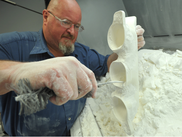
An operator manually removing powder (decaking) from a 3D printed part.
“Combining Deep Learning for 3D perception, smart mechanical design, motion planning, and force control for industrial robots, we developed a system that can automatically decake parts in a fast and efficient way. Through a series of decaking experiments performed on parts printed by a Multi Jet Fusion printer, we demonstrated the feasibility of robotic decaking for 3D-printing-based mass manufacturing,” the researchers wrote.
A classic robotic problem is bin-picking, which entails selecting and removing a part from a container. The NTU researchers determined that 3D perception, which “recognizes objects and determining their 3D poses in a working space,” would be important in building their bin-picking system. They also used a position-controlled manipulator as the baseline system to ensure compliant motion control.
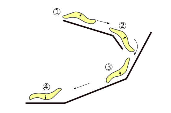
The NTU team’s robotic system performs five general steps, starting with the bin-picking task, where a suction cup picks a caked part from the origin container. The underside is cleaned by rubbing it on a brush, then flipped over, and the other side is cleaned. The final step is placing the cleaned part into the destination container.
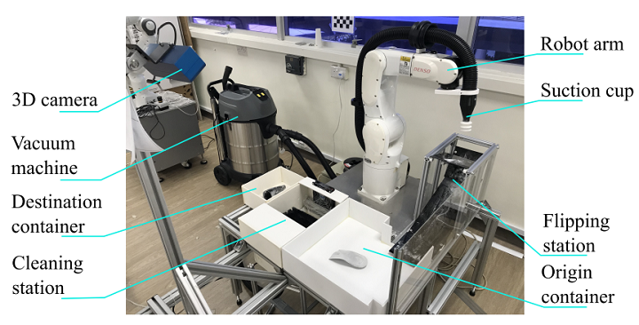
Proposed robotic system design for automated decaking.
Each step has its own difficulties; for instance, caked parts overlap and are hard to detect, as they’re mostly the same color as the powder, and the residual powder and the parts have different physical properties, which makes it hard to manipulate parts with a position-controlled industrial robot.
“We address these challenges by leveraging respectively (i) recent advances in Deep Learning for 2D/3D vision; and (ii) smart mechanical design and force control,” the team explained.
The next three steps – cleaning the part, flipping it, and cleaning the other side – are tricky due to “the control of the contacts” between the parts, the robot, and the brushing system. For this, the researchers used force control to “perform compliant actions.”
Their robotic platform made with off-the-shelf components:
- 1 Denso VS060: Six-axis industrial manipulator
- 1 ATI Gamma Force-Torque (F/T) sensor
- 1 Ensenso 3D camera N35-802-16-BL
- 1 suction system powered by a Karcher NT 70/2 vacuum machine
- 1 cleaning station
- 1 flipping station
The camera helps avoid collisions with the environment, objects, and the robot arm, and “to maximize the view angles.” A suction cup system was found to be most versatile, and they custom-designed it to generate high air flow rate and vacuum in order to recover recyclable powder, achieve sufficient force for lifting, and firmly hold the parts during brushing.

Cleaning station, comprised of a fan, a brush rack, and a vacuum outlet.
They chose a passive flipping station (no actuator required) to change part orientation. The part is dropped down from the top of the station, and moves along the guiding sliders. It’s flipped once it reaches the bottom, and is then ready to be picked by the robot arm.
Flipping station.
A state machine and a series of modules make up the software system. The machine chooses the right module to execute at the right time, and also picks the “most feasible part” for decaking in the sequence.
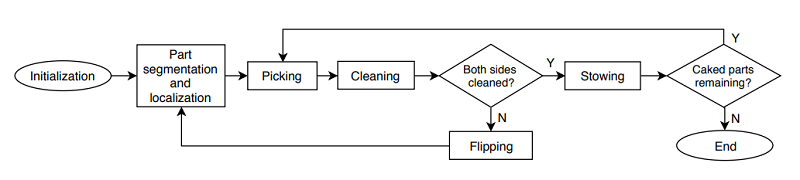
The software system’s state machine and modules perform perception and different types of action.
“The state machine has access to all essential information of the system, including types, poses, geometries and cleanliness, etc. of all objects detected in the scene. Each module can query this information to realize its behavior. As a result, this design is general and can be adapted to many more types of 3D-printed parts,” the researchers explained.
The modules have different tasks, like perception, which identifies and localizes visible objects. The first stage of this task uses a deep learning network to complete instance detection and segmentation, while the second uses a segmentation mask to extract each object’s 3D points and “estimate the object pose.”
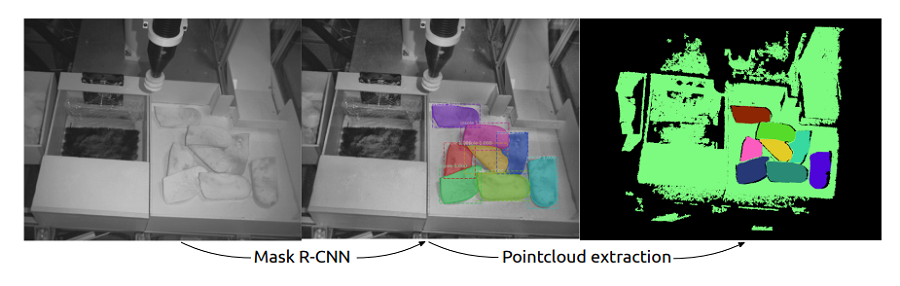
Example of the object detection module based on Mask R-CNN. The estimated bounding boxes and part segmentations are depicted in different colors and labelled with the identification proposal and confidence. We reject detection with confidence lower than 95%.
“First, a deep neural network based on Mask R-CNN classifies the objects in the RGB image and performs instance segmentation, which provides pixel-wise object classification,” the researchers wrote.
Transfer learning was applied to the pre-trained model, so the network could classify a new class of object in the bin with a high detection rate.
“Second, pose estimation of the parts is done by estimating the bounding boxes and computing the centroids of the segmented pointclouds. The pointcloud of each object is refined (i.e. statistical outlier removal, normal smoothing, etc.) and used to verify if the object can be picked by suction (i.e. exposed surfaces must be larger than suction cup area).”
Picking and cleaning modules are made of multiple motion primitives, the first of which is picking, or suction-down. The robot picks parts with nearly flat, exposed surfaces by moving the suction cup over the part, and compliant force control tells it when to stop downward motion. It checks if the height the suction cup was stopped at matches the expected height, and then lifts the cup, while the system “constantly checks the force torque sensor” to make sure there isn’t a collision.
Cleaning motion primitives remove residual debris and powder from nearly flat 3D printed parts. The part is positioned over the brush rack, and compliant force control moves the robot until they make contact. In order to maintain contact between the part and the brushes, a hybrid position/force control scheme is used.
“The cleaning trajectories are planned following two patterns: spiral and rectircle,” the researchers explained. “While the spiral motion is well-suited for cleanning nearly flat surfaces, the rectircle motion aids with removing powder in concave areas.”
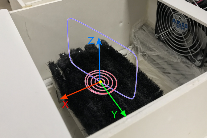
A combination of spiral and rectircle paths is used for cleaning motions. Spiral paths are in red. The yellow dot denotes the centroid of the parts at beginning of motion. Spiral paths are modified so they continue to circle the dot after reaching a maximum radius. The rectircle path is in blue, parameters include width, height, and direction in XY plan.
The team tested their system out using ten 3D printed shoe insoles. Its cleaning quality was evaluated by weighing the parts before and after cleaning, and the researchers reported the run time of the system in a realistic setting, compared to skilled human operators.

In terms of cleaning quality, the robotic system’s performance was nearly two times less, which “raised questions how task efficiency could be further improved.” Humans spent over 95% execution time on brushing, while the system performed brushing actions only 40% of execution time; this is due to a person’s “superior skills in performing sensing and dexterous manipulations.” But the cleaning quality was reduced when the brushing time was limited to 20 seconds, which could mean that the quality would improve by upgrading the cleaning station and “prolonging the brushing duration.”
Additionally, humans had more consistent results, as they are able to adjust their motions as needed. The researchers believe that adding a cleanliness evaluation module, complete with a second 3D camera, to their system would improve this.
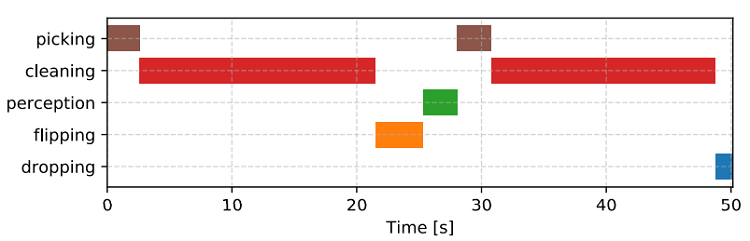
Average time-line representation of actions used for cleaning.
“We noted that our robot ran at 50% max speed and all motions were planned online. Hence, the sytem performance could be further enhanced by optimizing these modules,” the team wrote. “Moreover, our perception module was running on a CPU, implementations of better computing hardware would thus improve the perception speed.”
While these results are mainly positive, the researchers plan to further validate the system by improving its end-effector design, optimizing task efficiency, and adapting it to work with more general 3D printed parts.
Discuss this and other 3D printing topics at 3DPrintBoard.com or share your thoughts below.
The post NTU Singapore: Robotic Post-Processing System Removes Residual Powder from 3D Printed Parts appeared first on 3DPrint.com | The Voice of 3D Printing / Additive Manufacturing.