Improving Foundry Production of Metal Sand Molds via 3D Printing

Saptarshee Mitra has recently published a doctoral thesis, ‘Experimental and numerical characterization of functional properties of sand molds produced by additive manufacturing (3D printing by jet binding) in a fast foundry.’ Delving into hybrid casting and improved methods for creating metal molds, Mitra analyzes varied printing parameters and their effects on mechanical properties.

Centered around improving production in foundries, the author investigates ways to create molds in a completely automated manner, taking advantage of some of the most classic benefits in 3D printing—from greater affordability and faster production time, to better quality in prototypes and parts.

“Besides, the absence of tooling costs makes this process particularly economical, and much complex geometry that cannot be manufactured using traditional sand casting can be reconsidered,” states Mitra. 3D printers are generally faster, easier to use and cheaper than other add-on technologies. It is also possible to make foundry sand molds of extremely small dimensions and very thin parts. Modern foundry industries gradually use this Hybrid Casting technology because they provide ease of sand molding with good surface finish.”

The goal of Mitra’s thesis is to create molds for metal casting with greater stiffness and permeability—ultimately, for use in both the aerospace and automotive industries—applications we have seen significantly impacted by AM processes from car parts to rocket engines, to the qualification of important end-use parts.

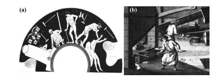
(a) Ancient Greece; bronze statue casting circa 450BC, (b) Iron works in early Europe: cast-iron cannons from England circa 1543 [4]

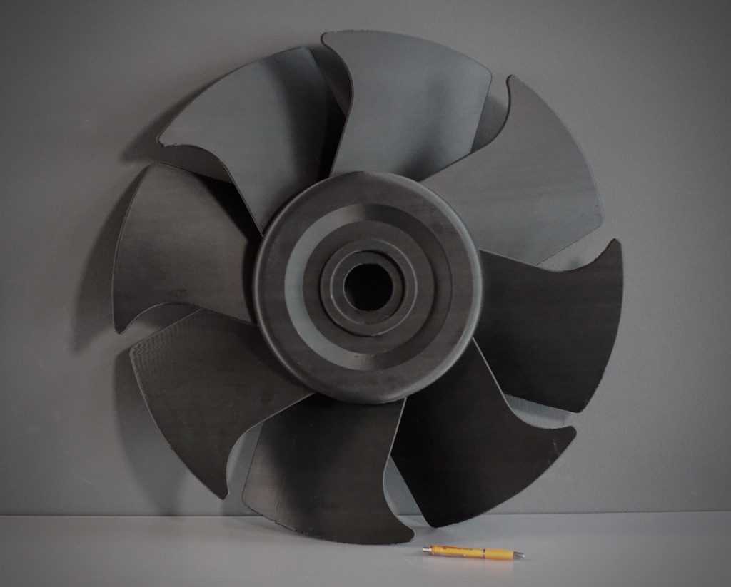
“Sand casting is the most widely used metal casting process in manufacturing, and almost all casting metals can casted in sand molds,” explained Mitra. “Sand castings can range in size from very small to extremely large. Some notable examples of items manufactured in modern industry by sand casting processes are engine blocks, machine tool bases, cylinder heads, pump housings, and valves.”

Metal casting requires:

  • Proper design
  • Suitable choice in material
  • Production of patterns for molds and cores
  • Selection of the casting process
  • Post-processing
  • Quality control

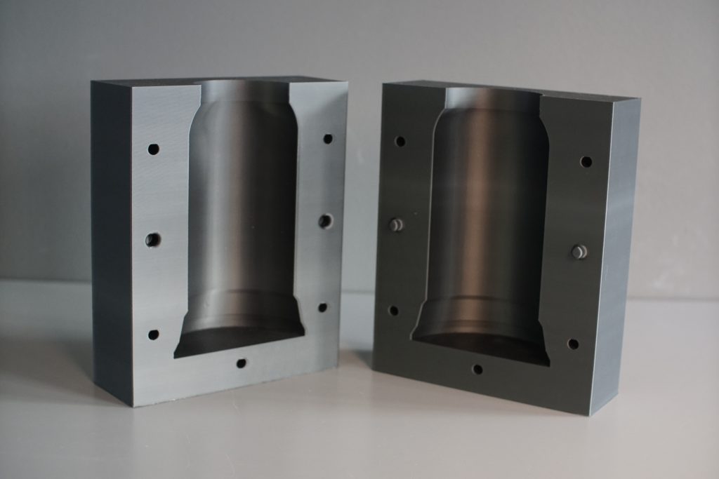
“Three-dimensional printing (3DP) of sand molds using binder jetting technology overcomes challenges faced in the traditional production method, e.g., limitations in terms of part complexity and size, production time and cost (which depends on the quantity and the part complexity, optimization in part design/design freedom for any castable alloys,” states Mitra.

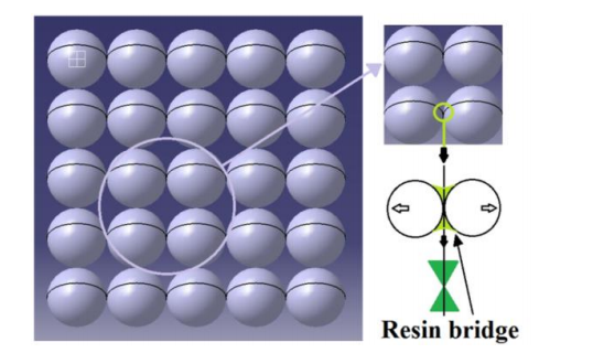
Schematic representation of particle binder bonding and resin

Powder binder jetting process

A series of chemically bonded 3D printed samples were examined. While binder amounts were evaluated by Loss on ignition (LOI) experiments, mechanical strength was measured via standard 3-point bending tests. Permeability was measured by the air flow rate through the ‘samples at a given pressure.’

Mitra learned that molds could be stored extensively at room temperature, but permeability of samples did decrease as temperature was raised.

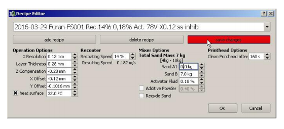
Printing recipe on ExOne 3D printer

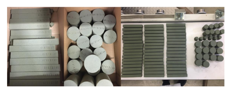
3D printed 3PB test bars and permeability specimens

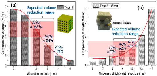
The author also noted that strength of the molds was ‘profoundly influenced’ by binder content, with increased amounts consequently increased mechanical strength.

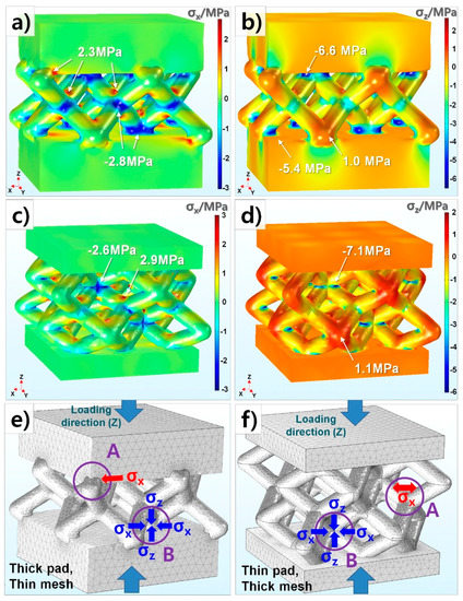
“X-ray µ-CT images were used to compute the porosity, pore size, throat size and the permeability of the 3D printed specimens for different binder contents and grain sizes, using analytical and numerical methods,” concluded Mitra. “The permeability predicted in the steady-state was compared with experimental and analytical measurements for layered silica grain arrangement. A major advantage of using X-ray CT characterization is the nondestructive nature of the tests. The computed permeability can be used as input to numerical simulations of metal casting allowing the prediction of macroscopic defects.”

“The present findings represent a step forward towards improved prediction of mass transport properties of the 3DP sand molds. However, further characterization of permeability of such additively processed sand mold should be performed with varying average grain diameter, to check the convergence of the present model. Also, samples printed with other printing process parameters should be studied.”

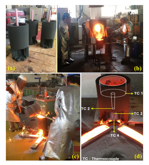
Steps involved, (a) 3D printing of sand mold, (b) melting iron, (c) casting process
and (d) eroded molded with the respective positioning of thermocouples.

What do you think of this news? Let us know your thoughts; join the discussion of this and other 3D printing topics at 3DPrintBoard.com.

[Source / Images: ‘Experimental and numerical characterization of functional properties of sand molds produced by additive manufacturing (3D printing by jet binding) in a fast foundry’]

The post Improving Foundry Production of Metal Sand Molds via 3D Printing appeared first on 3DPrint.com | The Voice of 3D Printing / Additive Manufacturing.

When Should 3D Printing Be Used in Sand Casting?

Complex casting with 3D printed mold (left) and traditional casting with traditional cores and molds (right)

Sand casting is a technology with a long history, but it’s being reinvented by additive manufacturing. 3D printed sand molds allow for highly geometrically complex castings, and in a paper entitled “Economies of Complexity of 3D Printed Sand Molds for Casting,” a group of researchers outlines the benefits of using additive manufacturing in sand casting:

  • the integration of structural elements such as periodic lattices in order to optimize weight versus strength
  • the structural inclusion of unique features such as embossed part numbers and/or other details of the production history
  • complex geometries that generate new casting applications not possible previously

In the paper, the researchers describe a complexity evaluation tool that scores CAD models to determine the most economical casting approach based on slicing and 2D geometry evaluation. The three potential outcomes include traditional sand casting; AM-enabled sand casting and a hybrid of the two with 3D printed cores in traditional casting flasks.

“Four algorithms were developed that all began by slicing each of the benchmark STL files and performing analysis per layer producing an average complexity across all layers,” the researchers explain. “This process was repeated for three orientations of each part and the results were averaged including: an unrotated case, a rotated case 90 degrees in X axis and rotated 90 degrees in Y axis. The rotations were completed in order to detect a complexity bias relative to orientation. For each orientation, the complexity numbers from all layers were individually calculated and then the total was divided by the number of layers for a mean value that was independent of the number of slices selected. By using more layers, the accuracy was expected to improve by improving the statistical sampling; however each additional layer meant an increase in the duration of computation.”

The complexity factor values for Algorithms A­D are shown for each of the benchmark castings. E indicates exterior. I indicates interior.

Algorithm A was the simplest and summed the number of contours detected for each layer. Algorithm B was similar to A except that instead of incrementing the sum of contours, a ration was calculated and added to a running sum. Algorithm C summed the number of contours but also included a sum of concavity defects that were sufficiently concave. Algorithm D was an aggregate of the other algorithms: the contours, the ratio of perimeter over area and the number of concavity defects summed together.

16 structures were selected for casting, ranging in complexity from simple spheres to a gyroid matrix and a Voronoi tesselation chess piece. The different castings were run through the complexity software, and the resulting data was compared to complexity scores assigned by previous work in which the scores were generated manually and correlated well with the decision as to which casting process was most suitable.

Of the four algorithms, Algorithm D gave values that “provide a decision boundary that was in line with the intuition of the authors as well as obvious extreme cases (sphere as a case of simplicity or a gyroid matrix for a case that can only be cast with the help of 3D printing),” according to the researchers.

“This layerwise complexity factor was compared to a known complexity factor for conventional casting fabrication method and showed similar results but without requiring design knowledge of the traditional methods,” the researchers state. “The economics of complexity and quantity were shown for a traditional casting tooling method and then compared to three methods that involved additive manufacturing.”

The researchers presented four options:

  • Traditional manufacturing (TM): Traditional subtractive processes to make molds / cores.
  • 3D Sand Printing (3DSP): Complete sand printing of both molds and cores.
  • 3D Sand Printed Core (3DSPC): 3D sand printing of cores and conventional pattern making for the mold ­cope and drag.
  • FDM Pattern­making (FDMP): Conventional core making and 3D printing using fused deposition modeling of hard patterns for conventional mold making with the advantage of faster mold fabrication.

The most economical method depended on the complexity and quantity of the parts being made. For example, for an air brake, 3DSP was the most cost effective regardless of level of complexity. However, 3DSPC was the most cost effective for more complex objects or objects in quantities of 100 or higher. For castings of low complexity, FDMP was the best choice, while for quantities of 1,000 3DSPC was the most cost effective for the full range of complexities.

Authors of the paper include Ashley Martof, Ram Gullapalli, Jon Kelly, Allison Rea, Brandon Lamoncha, Jason M. Walker, Brett Conner and Eric MacDonald.

Discuss this and other 3D printing topics at 3DPrintBoard.com or share your thoughts below.


Investigating Lightweight 3D Printed Structures for Sand Casting

3D printing is often used to produce molds for casting. In the case of sand molds, binder jetting is typically used; however, its high costs, due to expensive materials, need to be lowered, according to the authors of a study entitled “Mechanical Analysis of Ceramic/Polymer Composite with Mesh-Type Lightweight Design Using Binder-Jet 3D Printing.” In the study, the researchers investigate the mechanical properties of sand molds with a lightweight structure for low material consumption and short process time.

Binder jetting is a faster method of making sand molds than conventional casting, but it’s still too expensive, according to the researchers. In the study, they work to find a methodology of the lightweight design in a smaller length scale for binder jetting 3D printing, such as a typical conformal lattice cell in metal.

“To investigate the mechanical properties of lightweight designs, we introduce a basic unit block sample of a ceramic/binder composite applied to a whole sand mold using a BJ 3D printer in this study,” they explain. “The selection of two different structures was just done in this research for the purpose of comparing a typical lightweight design for metal with our ideal structure. We also address geometrical effects, such as the size and shape of typical lightweight patterns provided by commercial DfAM software on the basis of mechanical property evolution.”

To study the basic design factors of a lightweight structure for a sand/polymer composite, the researchers introduced two types of lightweight structures: a box with square holes (Type-1) and a lattice with upper and bottom pads (Type-2). The specimens were 3D printed using a sand binder jetting 3D printer from voxeljet.  A compression test was performed by placing the samples between circular steel plates. Each test was conducted twice for accuracy. Each sample was broken by initiation of cracks, and no creep was observed.

The researchers also conducted computational analysis in order to predict stress distribution and fracture under uniaxial-loading, and FEM simulations were carried out. Several major conclusions were reached from the study:

The strength of both designs significantly decreased with increasing volume ratio. The size of the inner hold in the Type-1 sample should be at least 2mm for taking out the inner sand powder cleanly. Although the Type-1 sample had higher strength, it was more difficult to take out sand particles from the samples than it was with Type-2. Therefore, future studies will focus on enhancing the low strength of the Type-2 sample.

With mesh-type lightweight structures, increasing pad thickness and decreasing mesh area results in increasing local stress concentration at the interface of the mesh and pads. Easy cracking is initiated at a comparatively weak boundary between mesh and pads in the case of thick pad thickness.

“Since a commercial software for topology optimization provides lightweight designs for rigid single component materials such metals or plastics, it is not suitable to apply the lightweight designs to a ceramic/polymer composite with different mechanical behaviors,” the researchers continue. “As a result, new types of light weight structures for sand casting molds are required to spread BJ 3D printing technology to the foundry industry.”

Finally, further work will suggest and evaluate the new lightweight and rigid design for additive manufacturing of a ceramic/polymer composite. It should reveal the correlation between structural and mechanical factors of the lightweight designs in detail.

Authors of the paper include Dong-Hyun Kim, Jinwoo Lee, Jinju Bae, Sungbum Park, Jihwan Choi, Jeong Hun Lee and Eoksoo Kim.

Discuss this and other 3D printing topics at 3DPrintBoard.com or share your thoughts below. 


Interview with BigRep CEO Stephan Beyer

Hot off of their announcement to partner with Bosh Rexroth we interviewed CEO Dr. Stephan Beyer of BigRep GmbH. The large format company seems to be excelling in partnerships and marketing. What is happening with the Berlin-based startup and where are they headed?

How is BigRep doing?

“We are seeing a very dynamic business right now, with BigRep and its partners leading the way in one of the 21 st century’s most exciting, disruptive technologies: 3D printing is already re-shaping Additive Manufacturing now in many industries. We are building the world’s largest serial production 3D printers, so we are experiencing a high level of interest and requests from industrial companies from around the world.”

What are your target verticals and types of companies?

“We are serving many different company types and industries, among them, of course, aviation, automotive, rail, design and architecture. We have a great many small- to mid-sized companies among our clients, but also major corporations. This reflects our highly flexible, customer-oriented approach. You need to listen to the industry. So we first identify and analyze the required application, which, in turn, drives the selection of performance materials, leading to the third and final step, the system as such, industrial AM equipment based on a 3D large-format printer.”

Why should I buy a BigRep?

“The top five reasons are these:

  • Size – with a capacity of over one cubic meter, the BigRep ONE provides the largest FFFbuilt volume currently available in the market.

  • “Made in Germany” – only our printers are based on the know-how of high-standard Germanengineering.

  • Technical quality – Our machines guarantee reliable, precise manufacturing with the highestlevel of iteration quality.

  • An open-choice approach for filaments.

  • Costs – BigRep printers are highly cost-efficient, both in acquisition costs and in long-term operations.”

How big is BigRep?

“We are headquartered in Berlin with a team of 90 engineers, developers, designers and experts from 22 different nations. As we are serving clients around the world, we also have offices in Boston and Singapore. In addition, we rely on an excellent global network of partners and re-sellers. We also have a global network of leading industry partners, such as Etihad Airways and Deutsche Bahn, as well as key investors – including BASF, Koehler, Klöckner and Körber.”

Are you aiming to make many small things quickly or large items?

“Actually both. One of the advantages of large-scale printers, of course, is to create large industrial objects in one single piece. But speed is of essence, too. So a fast extruder is quite important. For the ONE, we offer an optional Power Extruder with 0.6, 1 and 2 mm nozzles that can print 60% quicker, thus making our printer one of the fastest large-format 3D printers in the market.”

Will your machines grow bigger still?

“Well, they might depend on customer requirements. But more important is to make them faster and even more efficient – and more connected.”

You received EU funding, what did you use it for?

“The EU funding aims at supporting the growth of BigRep.”

What are the challenges when developing a 3D printer?

“Today, as any 3D printers, the large-format machines also will have to become faster and more efficient. They also need to offer interconnectivity and data in order to become a key element in smart factories and IoT applications. These are the challenges any manufacturer faces right now.

Where do you hope to see BigRep in five years?  What is BigRep’s ambition?
For us, it has always been about moving this technology and this industry forward. Studies show that the 3D printer market will grow by 20 per cent annually until 2020. A study by McKinsey forecasts a market volume of 100-250 billion Euros by then – and one of the driving forces behind this will be large-format 3D printing.

Given this background, we are aiming at taking a leading role in the 3D printing market for industrial manufacturing. Equally, we are aiming at further expanding the business while, at the same time, becoming the innovation and thought leader in the 3D printing industry.”

Do you see yourself as being a part of an ecosystem or developing a platform or just shipping a machine?

“We follow a comprehensive, sustained approach, so we develop complete solutions for integrated additive manufacturing systems, as well as a wide range of printing materials on an open-choice basis.”

What kind of industries do you think will use 3D printing for manufacturing in the near future?

“The same as today – automotive, aviation and transportation such as rail. In addition, medical technology, consumer goods, research and science are other promising areas of applications.”

Is sand casting important to you?

“It is a fascinating application. 3D models created by engineers with the use of a CAD software only need to be transferred to a BigRep 3D printer to be produced. It shortens the production cycle, reduces the use of resources and makes the complete process more cost and time-efficient. One example for this is the UK-based company Teignbridge Propellers International, which produces propellers for tugs, luxury yachts, fishing trawlers and ferries. Here, the BigRep ONE 3D printer is used to 3D print a full-size replica of the designed propeller to be the positive pattern for the cast mold, making the process faster by 33 per cent.”

3D Printing Combines with Other Technologies for Latest Energica Ego Component

Following the progress of the CRP Group and its subsidiary Energica over the past few years has been exciting, as the companies work together to develop 3D printed electric superbikes such as the Eva, Ego, and Ego Corsa. The Ego made its public debut at CES at the beginning of 2016, and has wowed the public not only with its performance but with the advanced manufacturing that went into its creation: 3D printing, using Selective Laser Sintering and CRP’s Windform family of materials, and CNC machining.

The Energica Ego continues to undergo development, and recently Energica engineers along with CRP staff worked together to focus on the motor housing, a complex, important component of electric motorcycles. From the beginning, the team worked to redesign the part in order to accommodate the rotor, stator, and speed reducer. The propulsion unit to be supported is flexible and compact enough that the Energica motor housing can be adapted to any vehicle, and the reducer is composed of a straight-cut gear train that adds strength along with simplicity of design. The structure holds the shaft and pinion and final drive to the wheel with a standard motorcycle chain.

To redesign the motor housing, the team had several requirements. The electric motor was heavy and needed to be balanced out by a lightweight housing, and because the motor generated high torque it required high resistance. The gears needed to be the correct size, and the materials and heat treatments would need to be carefully chosen.

The first step was creating a functional prototype, which was done by CRP Technology. It was manufactured using SLS technology and Windform LX 2.0, a composite polyamide-based material reinforced with a new-generation glass fiber now replaced by Windform LX 3.0. The prototype allowed the technicians to validate the 3D CAD drawing and helped Energica mechanics to work on the motorcycle’s development. It was mounted directly on the motorcycle, allowing for a full check of potential issues related to the assembly of each part.

“Being able to touch the 3D printed prototype of the motor housing was very important for us, as we are the ones who manage fit and assembly,” stated the Energica technicians. “For example, we have been able to study first-hand if the component can be assembled and disassembled easily; if all the parts can be reached; if it is possible to use standard wrenches … We must put ourselves in the shoes of those who will handle the motorcycle on the market: customers, dealers and mechanics of authorized workshops.

“Designing and creating a motorcycle is a team effort between designers, technicians and engineers. We deal with technological/engineering, design, functionality issues; the final aim is to match the work of the three sectors. The prototypes created in Windform 3D printing allow you to study the various elements, and to improve them where required by shortening development time and reducing costs.

“Through the combination of LS technology and Windform composite materials, it is possible to ensure the ongoing study of the components. The prototypes made in Windform are 100% functional, we can mount them on the motorcycle and test them on the road and on the track. We do not waste time which, at this stage, is very precious.”

The next step, after the validation of the CAD file, involved the creation of an aluminum prototype. The requirements included performance, light weight, and resistance to temperature. Using aluminum alloys 6082 and 7075, CRP Meccanica CNC machined the part with its 5-axis production systems. The central part, which was the largest, originally had a pass-through window to allow the motor to be positioned inside. Each side was a half shell, and one of the two halves held the gearing housing, sealed in with a cover. The other half housed the pinion and oil pan.


“This phase has been completed in a short time,” the technicians stated. “CRP supported us very much, and we did not have any problem with the component, both during the bench tests and the assembly on the motorcycle: the tolerances required were very complicated and tight, as the project included two rows of bearings (those on the motor, plus the outer ones to support the output shaft). Later, we were able to validate the road-going prototype.”

The next phase involved the realization of models for pre-series. The component was manufactured using traditional sand casting, with the same alloy used in the metal prototyping phase. The production of the part was truly a team effort – between Energica and CRP, and between three different technologies that worked together to produce a strong, lightweight and high-performing component.

Discuss this and other 3D printing topics at 3DPrintBoard.com or share your thoughts below.

[Images: CRP Group]


ETH Zurich researchers unlock new architectures with 3D printed molds

Over the space of two months, researchers on the MAS Digital Fabrication team at ETH Zurich created an experimental metal facade using 3D printed sand molds. Composed of 26 individual pieces and standing 3.5 meters high the so-called Deep Facade combines “the geometric freedom of 3D printing with the structural properties of cast metal,” to realize new possibilities in […]