Investigating Properties of Virgin, Sieved, and Waste 316L Metallic Powder for SLM 3D Printing

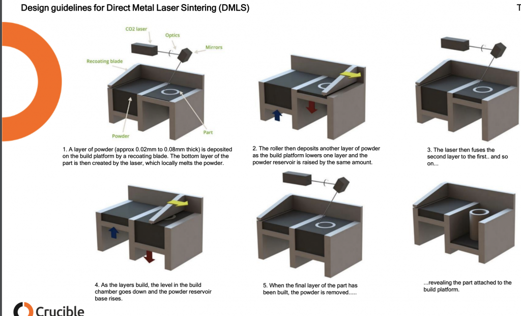
We often see metal 3D printing used to make steel parts, so plenty of research is being done regarding the material properties. Researchers from VSB – Technical University of Ostrava in the Czech Republic published a paper, “Research of 316L Metallic Powder for Use in SLM 3D Printing,” about investigating Renishaw’s AISI 316L powder for use in Selective Laser Melting (SLM) technology.

“Understanding the SLM process is extremely challenging, not only because of the large number of thermal, mechanical and chemical phenomena that take place here, but also in terms of metallurgy. The presence of three states (solid, liquid, gaseous) complicates the ability to analyze and formulate a model formula for proper simulation and prediction of part performance when printed,” they explained. “Since the SLM process operates on a powder basis, this process is more complicated by another factor compared to the use of other bulk material. The properties of the used printing powder define to a large extent the quality of the finished part.”

Because the material can impact an SLM 3D printed part’s final properties, powder research should be done ahead of time for best results. Particle size, shape, flowability, morphology, and size distribution are key factors in making a homogeneous powder layer, and using gas atomization to produce spherical particles helps achieve high packing density; this can also be improved with small particles.

The researchers investigated three phases of metallic powder present in the SLM process – virgin powder (manufacturer-supplied), test powder that had been sieved 30 times, and waste powder “that had settled in the sieve and was no longer being processed and disposed of.” They used a non-magnetic austenitic stainless steel, alloyed with elements like nickel and chromium and containing a low percentage of carbon.

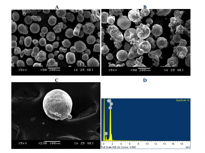
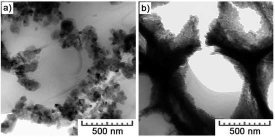
Scanning electron microscopy (SEM) was used to investigate the powder morphology, which “affects the application of metal powder by laser in terms of fluidity and packing density.” First, the shape of the powder particles was measured and evaluated, and then a visual quality evaluation was completed to look at the spherical quality and satellite (shape irregularity) content. The team found that many particles had satellites, but that this number increased in over-sized powder.

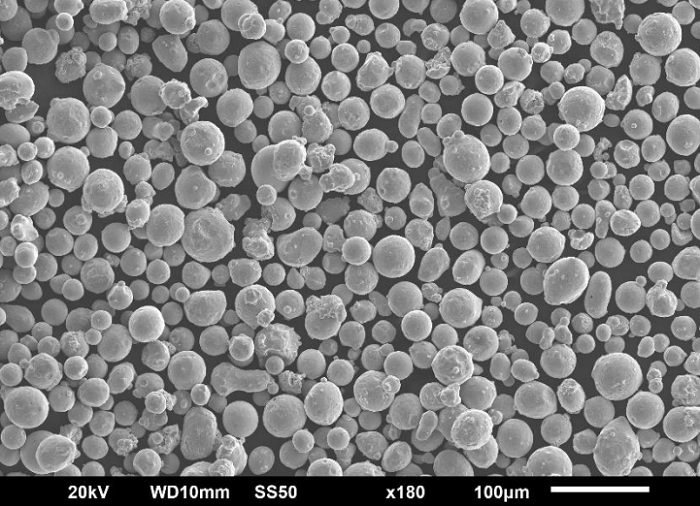
Fig. 1. SEM image of virgin powder 316L, magnification x180

“The measurement of virgin powder (Fig. 1) reveals that the production of powder by gas atomization is not perfect and the shape of some particles is not perfectly spherical,” the researchers wrote. “It is also possible to observe satellites (small particles glued to larger ones, Fig. 2), which are again a defect of the production method.”

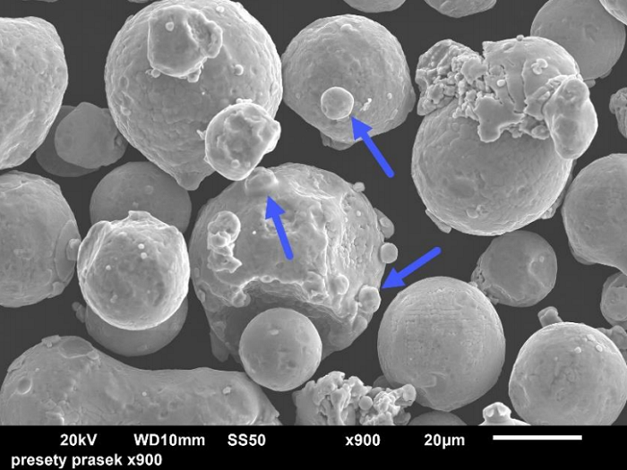
Fig. 2. Satellite illustration, magnification x900

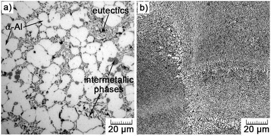
They found that the particle shape was “not always isometric,” and that cylindrical, elongated, and irregular shapes appeared alongside spherical particles in over-sized powders.

“Another interesting phenomenon was manifested in the sieved powder, where particles with a smoother and more spherical surface were observed than the original particles. This is most likely due to the melting and solidification process that is specific to AM,” they noted.

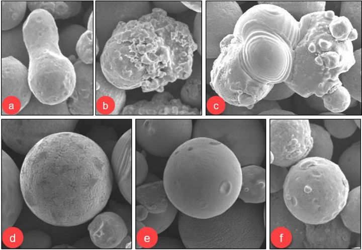
Fig. 3. Morphological defects – a) particle fusion; b) gas impurities; c) agglomeration – sintered particle;
d) dendritic particle structure; e) spherical particle; f) particles with a satellite

An optical method was used to measure powder porosity. The 316L powder was embedded in a resin, and was “1 mm layer abraded” post-curing before the particles were cut in half and polished with diamond paste. The images captured via microscope were loaded into analysis software, which determined that the total density of the powder was 99.785%.

“In general, pores must be closed from 3/4 of their circumference to be considered pores,” the team explained. “Particles that do not comply with this rule are automatically considered irregular particles.”

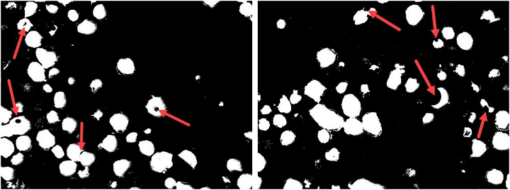
Fig. 4. An example of open pores that correspond to the rule (L), and pores that do not conform (R)

The researchers also measured the size of all individual pores and recorded which ones began at 5 µm, though they noted that due to potential image resolution issues, “pore sizes of about 5-8 μm should be taken with some uncertainty.”

Fig. 5. Pore size measurement of 316L metallic powder

A histogram showed that, in the metallic powder particles, the “15 µm pore size was most present,” and that the largest was 30 µm.

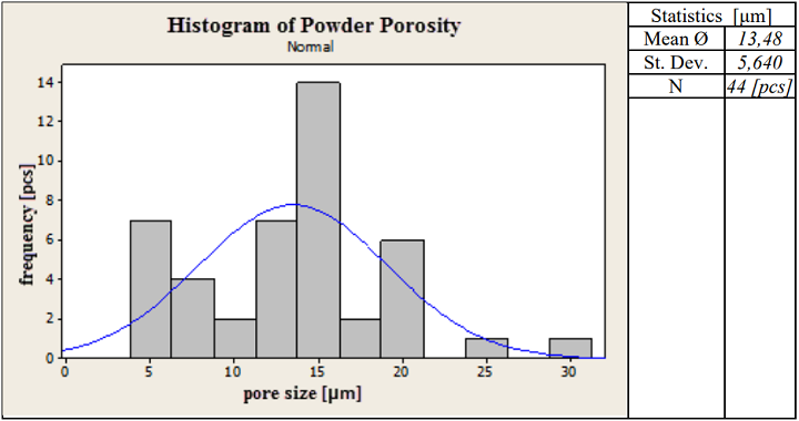
Table 3. Measured values of porosity of powder particles

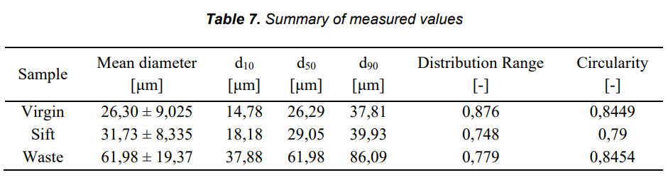
Finally, they used an optical method to measure and examine grain size distribution of the virgin and sifted powder. Using 200x magnification, measurements were taken at five random locations, each of which had roughly 200 particles on which they performed static analysis. The results were processed with statistical software, which created cumulative curves to indicate how many particles were smaller or larger than a certain size.

“Of these, the quantiles d10, d50 and d90 were obtained, which express the cut-off limit within which the size falls to 10, 50, 90 % of the measured particles,” they wrote.

The average particle size only increases a little by repeatedly sieving the metallic powder, but because of irregular particles, agglomerated or molten particles larger than 45 μm, they fall through the mesh. Results show that <10 µm particles are reduced, while larger particles are increased, in the sift powder. But, the team notes that the powder is still usable.

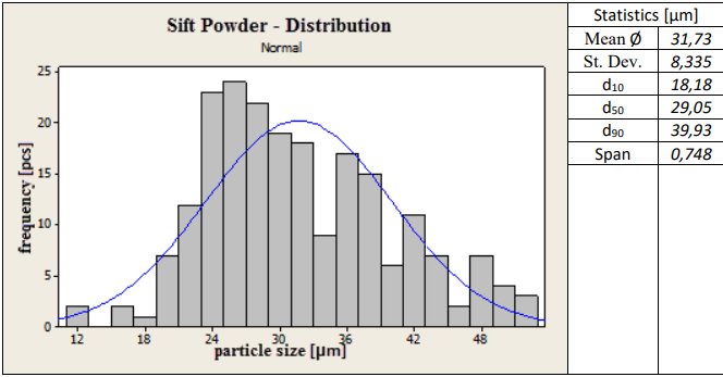
“The sift powder showed an increase in particle volume and surface area while circularity decreased, indicating that virgin powder generally has a higher sphericity,” the team explained.

They found defects like agglomeration, gas impurities, and particulate fusions at all three stages, but since the powder is still usable, they concluded that SLM is both an economic and ecological technology. The researchers listed several measures to take in order to “achieve the best possible consolidation,” such as high purity, fine surface, low internal porosity, tight particle distribution, and as few surface pores and satellites as possible.

Discuss this and other 3D printing topics at 3DPrintBoard.com or share your thoughts below.

The post Investigating Properties of Virgin, Sieved, and Waste 316L Metallic Powder for SLM 3D Printing appeared first on 3DPrint.com | The Voice of 3D Printing / Additive Manufacturing.

Ti6Al4V in Selective Laser Melting: Analysis of Laser Polishing Techniques

Chinese researchers are expanding on new materials and technology for improving surface quality in metal 3D printing, outlining their findings in ‘Laser Polishing of Ti6Al4V Fabricated by Selective Laser Melting.’ SLM technology allows for fabrication of complex parts and is becoming increasingly more popular due to the latitude allowed for designers and researchers, as well as greater efficiency in production.

In this study, the researchers focus on the positive benefits for bioprinting, and the versatility offered for fabrication of implants related to bone fusion. Inferior surface finish is one of the greatest challenges, however, resulting in the following issues:

  • Stair-step effect
  • Low-dimensional precision
  • Increased friction
  • Low therapeutic effect

“Various conventional post-processing treatments, such as sandblasting, chemical polishing, electrolytic polishing, machining, ultrasonic polishing, and oxidation have been used on metallic AM (Additive Manufacturing) components to reduce their surface roughness. However, several drawbacks, such as being time-consuming, it is difficult to obtain machine precision components, chemical risks, and low efficiency, limit the clinical application and development of these treatments,” explain the authors.

Laser polishing can solve some of these problems, working with smaller, complex parts that require accuracy, and offers the capability of high-speed polishing at lower cost. Laser polishing also refines mechanical properties, offering improvement which is of ongoing interest to users around the world whether in experimenting with composites, color, 4D materials, or more.

“A comprehensive analysis of the roughness, porosity, fatigue behavior, and biocompatibility, along with the relationships between them, of components after LP should be conducted prior to applying LP technology to implantable medical devices,” explained the researchers regarding the motivation for their study, as they worked to improve on surface roughness and resulting finish.

“The findings of this study can play a guiding role in other processes that involve biomedical materials,” said the researchers.

All samples, created with Ti6Al4V alloy, were polished in a rectangular cavity with argon, used to decrease the possibility of oxidation on parts.

(a) Test specimens; (b) a schematic view of the laser polishing (LP).

During analysis, samples displayed metallic ‘globules,’ which the researchers noted were ‘only loosely bonded during additive manufacturing processes. Small particles and microcracks persisted, however, displayed on the LP-1 sample, while the LP-2 sample was polished with no defects. For sample LP-3 there was concern over reconstructed islands and cracks.

Scanning electron microscope (SEM) images of the (a) as-received sample, the (b) LP-1 sample, the (c) LP-2 sample, and the (d) LP-3 sample.

Laser scanning confocal microscope (LSCM) images of the (a) as-received sample, the (b) LP-1 sample, the (c) LP-2 sample, and (d) the LP-3 sample.

While laser treatments caused changes that affected wettability, the authors note that some previous research has shown a positive connection related to surface topography. In evaluating pore distribution, samples were analyzed as the researchers sliced then from a variety of lengths from the surface. All samples displayed mechanical properties that were similar, in terms of tensile and yield strength and elongation. With the exception of the high-cycle fatigue test, fatigue behavior was almost the same in all samples.

The pore distribution of the as-received sample at different distances: (a) 0–10 μm; (b) 30–40 μm; (c) 60–70 μm, and (d) 70–100 μm. The pore distribution of the LP-2 sample at different distances: (e) 0–10 μm; (f) 30–40 μm; (g) 60–70 μm; and (h) 70–100 μm. (The purple part of the image, after threshold segmentation, is the pore.)

Mechanical properties: (a) microhardness distributions in the laser-polished layer, (b) tensile properties, (c) stress–life fatigue behavior for all geometries showing combined data points, and (d) stress life fatigue curves.

“The cell experiment showed that the LP-2 parameters improved cell adhesion and exhibited cell proliferation. The results indicate that LP improved the cell biocompatibility, while hydrophilicity positively affected early cell adhesion,” concluded the researchers.

What do you think of this news? Let us know your thoughts! Join the discussion of this and other 3D printing topics at 3DPrintBoard.com.

Adhesion and proliferation of MC3T3-E1 cells grown on different sample surfaces. (a) The as-received sample, (b) the LP-1 sample, (c) the LP-2 sample, and the (d) LP-3 sample. In images a–d: F-actin cytoskeleton of osteoblasts (red) and cell nuclei (blue) after 1 day of seeding.

[Source / Images: ‘Laser Polishing of Ti6Al4V Fabricated by Selective Laser Melting’]

The post Ti6Al4V in Selective Laser Melting: Analysis of Laser Polishing Techniques appeared first on 3DPrint.com | The Voice of 3D Printing / Additive Manufacturing.

BeamIT and SLM Solutions expand cooperation on metal AM

BeamIT, an Italian additive manufacturing service bureau, and SLM Solutions have signed an agreement to expand its long term cooperation. BeamIT will also expand its product portfolio with two new machines – the SLM 280 2.0 and SLM 500 – with which it will continue to test new machine settings and metal powders.  “We are […]

Bossard Group continues 3D printing expansion with 30% stake in Ecoparts  

Bossard, a Swiss fastener technology and logistics group has acquired a 30% share in fellow Swiss company Ecoparts, a 3D printing service bureau. The move is the latest in a series of 3D printing deals made by the company in the last few years. Commenting in relation to the new shares, the company stated, “This […]

Singapore: Researchers Study Effects of Spatter in Large-Scale SLM Printing

Ahmad Anwar, thesis student at Nanyang Technological University in Singapore, explores undesired byproducts of 3D printing in ‘Large scale selective laser melting : study of the effects and removal of spatter by the inert gas flow.’ The topic of spatter is usually considered in regard to imperfections, but here Anwar explores such issues in connection with fabrication on the larger scale too—a necessary method that results in hardware of increasing sizes so that larger parts can be made.

Large scale selective laser sintering can be restricted by powder weight, along with other features such as the number of lasers, and powder bed area. For successful SLM printing, Anwar states that the study of spatter particles is necessary. Spatter is notable due to its size and darker color, and effect on 3D printed layers—along with inducing porosity. The goal of the research study was to find out more about effects of spatter on the manufactured parts, analyze how they impacted mechanical properties, and simulate the activity of spatter in 3D printing during inert gas flow.

Anwar also studied ‘suitable ejection profiles,’ as well as what performance would be like without any inert gas flow at all. The researchers used an SLM Solutions 280 HK machine for their experiments and chose argon as the gas of choice for exploring spatter.”

“With respect to the spatter particles on the powder bed, the mass and size distributions were characterized,” states Anwar. “The Stokes (Suk) number was then used as a parameter to observe the gas flow effectiveness in the spatter transport, which accounts for particles suspended in the gas flow. Image processing was also applied in order to immediately characterize the spatter distribution on the powder bed.”

The researchers set up a camera to monitor spatter and then processed them for comparison with the mass distribution characteristics. As Anwar explains, spatter usually occurs during any SLM printing process as such particles are ejected and often accumulating near processing regions or the powder bed. The volume of spatter is also dependent on energy output like:

  • Laser power
  • Scanning speed
  • Layer thickness
  • Hatch spacing

Schematic of spatter ejection from melt pool and its transport by the inert gas flow (green arrows) in the -x direction.

Higher energy input resulted in larger spatter, increased scattering, and greater jetting height. As the researchers experimented with methods to reduce the spatter, they pumped gas into the chamber:

“For the SLM Solutions machines, argon gas is pumped in from the right to the left side (in the negative x direction). There are two reasons for the introduction of the inert gas; Firstly, oxidation of the molten powder needs to be minimized as much as possible. Hence, scanning only starts when oxygen content is below 0.05%. Secondly, during the scanning itself, the flow of gas aids in the removal of unwanted spatter as a result of the ionized metal vapor and plasma plume that exert recoil pressure on the melt pool,” stated Anwar.

The researchers collected 15 samples of spatter, with each one measured and evaluated after being scooped from a deposit area near the outlet.

“The reasons why we chose to collect the spatter at that area are: (i) it is not possible to collect the spatter directly on the powder bed as it is mixed with fresh powder; (ii) it is not possible either to collect the powder blown out of the outlet, as one cannot completely clean the powder collector (gas filter) between runs; (iii) on the contrary, the region near the outlet where the powder is collected in our experience could be cleaned up several times per run, resulting in reliable results; (iv) finally, it can be safely assumed that the quantity of the powder collected near the outlet is proportional to the total quantity blown out of the powder bed and that its composition is similar,” states the author.

SEM images of A: Fresh powder; B: spatter collected near the outlet observed;
C: Single particle of spatter. D: Sample EDS result of single spatter

Simulations were performed to analyze how gas crossflow contributes to moving spatter away from laser-scanned regions. Argon gas was not substantially impressive in removing spatter to the outlet. The researchers also found that increasing gas flow velocity did not reduce the number of particles in the powder bed.

“Interest in large scale AM processes have generated much research on the issues hindering the development of larger machines, and it is no exception for SLM,” concluded the author. “The prospects of manufacturing larger parts for the aerospace and automotive industries are deemed to be very attractive.

“The results reported from the experimental and simulation studies of the spatter particle distribution on the powder bed could prove to be significantly and scientifically beneficial for the development of an optimized inert gas flow system. In the future, such improvements made to remove spatter particles over a larger powder bed area would realize the possibility of producing larger SLM machines capable of fabricating even larger parts than current standards.”

Almost as soon as we realized the miraculous potential of 3D printing and the infinite choices for innovation before us, it was time to start critiquing and improving—and just as the technology is based on a layer by layer approach, its continued progress has been made with one improvement mounting on another. Flaws in 3D printing must be addressed, however, as many parts are relied on for strength and functionality. The study of spatter is important in trying to reduce or eliminate any defects. In other studies, researchers have studied ejecta and its role in causing imperfections, other types of spatter, and have even set up high-speed cameras to study 3D printing in situ. Find out more about the impact of spatter in large scale selective laser melting here.

[Source / Images: ‘Large scale selective laser melting : study of the effects and removal of spatter by the inert gas flow’]

Powder accumulation on left side of SLM Solutions 500 HL build chamber

Design Guidelines for Direct Metal Laser Sintering, Selective Laser Melting, Laser Powder Bed Fusion

Perchance I came across an excellent document on the design guidelines for  Direct Metal Laser Sintering, also called DMLS, Selective Laser Melting, SLM, Laser Powder Bed Fusion and referred to as metal 3D printing. This document was made by UK based design consultancy Crucible Design. Crucible Design was founded in 1990 by Hugh Raymond and Mike Ayre who for the past 28 years have been tackling tough, complex advanced engineering and design projects. Whether working on cost reduction projects or bringing completely new products to market Crucible Design has carefully built up its reputation over the decades. I was so impressed with Crucible’s design guidelines for metal printing document that I asked CEO Mike Ayre if we could republish it here. I also asked him how he came to make it.

The main reason behind my work with metal 3D printing was the SAVING project, which was run by a consortium in 2011 and 2012. The consortium consisted of Exeter University, ourselves, Plunkett Associates, Delcam, EOS and Simpleware. The point of the project was to find ways to use additive manufacturing to reduce energy use. As the processes themselves are so energy intensive, we soon concluded that the only way to achieve the objective was through the use of the parts, not their manufacture. This is where the airline buckle project came from – reducing the weight of the plane to minimise fuel wastage.

The main problem with metal 3D printing was the same as all design approaches to additive manufacture: early promoters pushed the idea that there were no design limitations, and we ‘were only limited by our imagination’. In fact, this proved to be completely wrong, with 3D printing just having different limitations to conventional methods. In terms of metal printing, the main one is the need to machine out the support structures that are required for any downward facing horizontal surface (the kind of thing that can be washed away using and FDM machine). This requires any efficient design to adopt almost medieval approaches to design, with pointed arches and sloping surfaces that can be built without supports.

Why did you make the guide?

The main reason for making the guide was to inform designers of some of the basic rules and encourage a more creative approach to the use of 3D metal printing and additive manufacture in general. It has been good to see that, since it was written, there is a lot more discussion about appropriate design methods for additive manufacture.

Now the guide was published in 2015 which is eons in 3D printing land. However, the same process limitations and design rules persist. I’ve made design guidelines and design rules documents before and was super impressed with how clear and concise this one was.  I think that this is a very valuable resource to people in metal printing today either to learn about designing for metal 3D printing or to use as a teaching aid to help others. If you’re in a design project with a customer then this is also super helpful in trying to let them see that “complexity is free only in dreams.” I am absolutely certain that these images will be spread far and wide, do please credit Crucible Design for their hard work, be mindful that these images are still their copyright and reach out to them should you need any 3D printing design services done. The images below are all Crucible’s the comments are mine.

Below we can see how DMLS works. A layer of metal powder around 40 micron in diameter and round but not too round is deposited on a build platform and spread out by a recoater. This may be a roller or a knife blade type of recoater. The laser fuses the powder that will make up your part leaving the other loose powder behind. To keep your part from ripping itself apart due to thermal stress supports are needed which will be removed later.


While the build plates below seem very full and indeed parts can be stacked efficiently often single parts are built at a time and parts are not stacked. This has to do with the fact that much of the industry is not yet optimized for production and worry that layer skips or recoater bumps and other errors will disrupt a week long build four days in. Note the high amount of manual labor required here. Every one of the bottom column steps will require a person lifting a few kilos at least to a new station or machine. Not shown here is the manual removal of loose powder. In addition to EDM CNC or tumbling (sometimes for a week or more) may be used as well. Depending on the needed Ra and finish of the part many steps will be required including quality control steps such as CT scanning the part to make sure that there are no internal tears or holes.

Parts built in such a way as to make it easy for the recoater to hit them with any force and its best to mitigate part strength in such a way that when that does happen your build doesn’t fail.

Overhanging surfaces in DMLS can be very rough indeed this may require a lot of post-processing. Occluded holes could trap material inside or require supports that can not be removed while large holes could cause parts to tear themselves asunder.

Another thing to consider below is, can the final part withstand the removal of the suports? 

Designing supports that are easy to remove saves a lot of labor. Often a staff member with a flex or circular saw will be cutting away supports. Making sure that this person could do this without damaging the part reduces time and the need to rebuild a part.

Below are some simple support strategies for DMLS. Often a person with decades of experience can do this in their head. While there are some tools that build supports, support strategies for parts still require a lot of experience and thought. Often it will take days for a build and post processing to complete. If you then after four days find out your part has failed then you have to do another iteration. When making completely new geometries several part failures are common. If you have a type of geometry understood (acetabular cups, teeth) then you can print millions of them in many variations.


Comparing 3D Printed Parts to Parts Produced by High Pressure Die Casting

Additive manufacturing has, in many studies, been compared with traditional manufacturing techniques like, for example, injection molding. In a study entitled “The Use of Selective Laser Melting to Increase the Performance of AlSi9Cu3Fe Alloy,” a group of researchers compared parts made with 3D printing to parts made with die casting, using the same material.

Aluminum and its alloys have an excellent strength to weight ratio, and AlSi9CuFe is frequently used in the automotive industry because of its mechanical strength. It is easy to machine and is usually processed by high pressure die casting, but the method has its imperfections.

“High-pressure die casting (HPDC) enables high production volumes of parts showing high surface quality,” the researchers state. “Compared to gravity casting, even more complex shapes are possible to be produced, but still, the current demands for porous structures or very small dimensions are hardly attainable. Additionally, the HPDC process is limited by the formation of defects, such as oxide films, shrinkage cavities, air porosity, etc., which cannot be eliminated. Such defects then weaken the castings structurally and exclude them for use in the field of safety applications.”

Therefore, the researchers conducted a study in which SLM 3D printing and high pressure die casting were used to produce parts using the same alloy. They then compared the properties of the parts. Porosity was examined in the samples, and transmission electron microscopy was used to observe nanoscale microstructural features. Uniaxial tensile tests were conducted, as were compressive tests and hardness measurement. Fracture surfaces were studied using scanning electron microscopy.

TEM bright field images obtained in the area of (a) a melt pool boundary and (b) a melt pool interior.

“Compared to as-cast microstructure consisting of α-Al dendrites and lamellar Al-Si eutectics, SLM yields in hierarchically heterogeneous microstructure,” the researchers conclude. “Grains are arranged in melt pools representing material melted and solidified by single laser tracks in the direction of the highest temperature gradient. They exhibit very fine cellular substructure in which the cells of α-Al solid solution oversaturated in Si and Cu are separated by eutectic network formed by cubic particles of pure Si, here 30–70 nm in size.”

The 3D printed parts showed a very fine microstructure, and overall, the parts produced by additive manufacturing exhibited greater strength than those produced by die casting, as well as greater plasticity. This is notable because it shows that 3D printing can overcome the strength-ductility tradeoff that is present in so many metals and alloys. The researchers conclude that 3D printing can improve the performance of the alloy compared to high pressure die casting, as well as produce more complex and lightweight structures, opening up new applications.

Comparison between (a) as-cast (HPDC) and (b) SLM microstructures.

This study is another example of how 3D printing can improve upon traditional manufacturing techniques. 3D printing is often hailed for its ability to speed up production, save money, and produce more complex and lightweight components than traditional manufacturing, but the researchers’ study shows that the very microstructure of 3D printed materials can be superior to that of the same materials fabricated in a traditional way.

Authors of the paper include Michaela Fousova, Drahomir Dvorsky, Marek Vronka, Dalibor Vojtech and Pavel Lejcek.

Discuss this and other 3D printing topics at 3DPrintBoard.com or share your thoughts below.

Building Conformal Cooling Channels Using 3D Printing To Reduce Warpage and Cooling Time

Bottom view of the parts produced by both conventional mould tool (left) and AM mould tool (right)

In injection molding, parts are cooled by building channels throughout them. Those channels are typically straight lines, which can result in uneven cooling. Much more even, efficient cooling can be achieved with conformal cooling channels, which conform to the shape of the part. However, these types of channels are difficult to produce by conventional methods, making 3D printing an appealing alternative for the creation of injection molding tools. In a paper entitled “Conformal cooling by SLM to improve injection moulding,” a group of researchers use Selective Laser Melting to build conformal cooling channels in injection molding tools.

Specifically, the study aims to produce tooling for a support for pipette tips used in the medical industry. The main problem with conventional production of the part, the researchers explain, is a long cycle time, related to cooling difficulties on the thickest areas of the part.

“Furthermore, the high quantity of ejector pins on the core side creates additional problems since minimum distances must be kept from cooling channels,” the researchers continue. “To evaluate the impact of conformal cooling, numerical simulations were performed, providing excellent prospects concerning cycle time reduction.”

The plastic part they created for the study was a support for pipette tips, a rectangle with 12×8 housings for the tips, divided by thin walls. The part was designed to be stacked, with stronger outer storage walls. Trials were carried out with conventional manufacturing techniques, and certain thick spots at the intersection of the inner walls and the outer walls caused hot spots, where the material cooled slowly. This in turn caused sink marks and warping on the inner walls.

The researchers then re-engineered the mold to be produced with additive manufacturing, using a LaserCusing machine from Concept Laser. The two goals with the re-engineering were the reduction of cycle time and the prevention of warping. Using conformal cooling channels enabled them to reduce the cooling time from 35.5 seconds to 18 seconds.

“The second but not less important goal is to reduce temperature difference in order to prevent warpage,” the researchers state. Numerical results show that, with this design approach, temperature difference is significantly lower. The comparison between several nodal temperatures on different areas of the part shows that the highest temperature difference is now 10.6ºC.”

Overall cycle time had a significant reduction of 34.2%. The researchers also looked at the economic feasibility of producing injection mold tooling through 3D printing, and found that SLM costs as well as lead time were higher. However, manufacturing costs could be optimized if the cavity and core inserts were built in a single process. The researchers also foresee several other benefits to using additive manufacturing for the 3D printing of injection molding tools, including energy savings, scrap reduction, productivity and overall efficiency.

This study is not the first to confirm the effectiveness of using 3D printing to produce injection molding tools. Injection molding is an effective manufacturing technology in itself, but it has room for improvement, and additive manufacturing – rather than replacing injection molding completely – can improve it in a way that makes it even more efficient.

Authors of the paper include N. Reis, F.M. Barreiros, and J.C. Vasco.

Discuss this and other 3D printing topics at 3DPrintBoard.com or share your thoughts below. 


Wolfmet 3D 3D Prints 100% Tungsten Using SLM Showcases Its Products at TCT Birmingham 2018

Wolfmet 3D is the commercialization of 3D Printing methods developed at M&I Metals to 3D print tungsten. The company is a service bureau that makes tungsten 3D printed components for industry. Tungsten is not completely new to 3D printing with us having written about a study looking into the parameters of 3D printed tungsten and looking at Philips subsidiary Smit Rontgen 3D printing tungsten.

Now, Wolfmet 3D will try to conquer the world with this very special very dense material that for our industry is very exotic. To introduce their product the Wolfmet3D team is exhibiting at the TCT show in Birmingham and we interviewed them about 3D printing tungsten. Curious about them? Check them out at stand G41.

What is Wolfmet 3D?

Wolfmet 3D is the revolutionary additive manufacturing process whereby we produce 3D printed parts via SLM. It allows us to make parts which would either be impossible or not economical using traditional subtractive techniques.

What are the applications for 3D printed tungsten?

Extensive! It really is a very exciting time. Medical and industrial imaging in many ways are at the forefront of recent developments, but we are making new advances all the time in other areas too. To give just one example, we are in discussions with clients interested in tungsten’s heat resistant properties, which opens up another field of possible applications.

Tungsten is a very heavy metal. We almost always think about lightweighting things using 3D printing. But your material is used to make things heavier?

As you indicate, tungsten has a very high density (approx. 60% denser than lead). In the applications we have discovered so far for Wolfmet 3D, it is valued for its radiation attenuation properties, derived from the density, and also its heat resistance. The weight is really incidental.

What do you see as future applications for 3D printing tungsten?

Future opportunities are perhaps only limited by our own imagination, so our specialists work in partnership with leading research institutes and universities to ensure we are at the forefront of new developments across the globe.

How is tungsten used in vibration damping?

Tungsten’s high density enables it to act as a vibration weight in various dynamic applications.

Why does one want to 3D print a collimator?

The collimator’s function in an imaging system is to focus beams of radiation (gamma or x-ray) onto a detector and to filter out stray beams which might distort the signal. The detector’s software converts the signals into a 3D image of the subject. Until the arrival of Wolfmet 3D, most collimators were made from lead. Lead has several disadvantages – it is toxic and has to be handled with care and it is relatively soft. Most importantly, from the point of view of imaging systems, its density is much lower than that of tungsten. As a result, lead collimators are much less effective in screening out stray beams and, therefore, give inferior image quality.

What is the DEPICT system?

The DEPICT system was developed by a consortium which included Kromek and the University of Liverpool. Its function is to measure the amount of radioactivity issuing from a thyroid cancer patient during radiation therapy. This enables the medical staff to personalise the dosage of each treatment according to the patient’s physique and metabolism. The DEPICT team acknowledged early on that a tungsten collimator would give much more accurate readings than a lead one and we are very proud to have worked with them on this project.

Do you see many more applications in MRI or imaging generally?

Yes absolutely, Wolfmet 3D helps to make the innovations of our clients possible. Wolfmet tungsten has been shown to be MRI compatible in terms of its magnetic properties. This, together with the advantages that using tungsten can bring, makes it an exciting prospect for the future.

Are imaging apertures also a good application for your technology?

“In principle, yes, if the design is complex, as is increasingly the case.”

Isn’t shrinkage a huge problem with tungsten?

There is no shrinkage with the SLM technology which we use. I believe that this is not always the case with other Additive Manufacturing methods.

What kind of part properties can you get with this material?

The density is typically 94 – 96%. We have a continuous improvement programme designed to optimise the physical properties.

What kind of alloys are available?

At present we offer 100% tungsten components but as this is such a rapidly developing market, we are of course looking at other options. We have clients who are interested in developing other tungsten-based materials, but I’m afraid that I am also prevented from saying more due to our confidentiality agreements.