3D Printed Surfboard: Researchers Test Different Bio-Inspired Core Structures

Just as a New Zealand-based surfer was inspired by the humpback whale and the microgrooves of shark skin when creating his surfboard fins, so too was a team of international researchers inspired by the natural world in their structure study of an on-water sports board. In their recently published paper, “3D Printing On-Water Sports Boards with Bio-Inspired Core Designs,” they explain their work advancing the board by using 3D printing and different bio-inspired core structures, such as the honeycomb.

“Modeling and analyzing the sports equipment for injury prevention, reduction in cost, and performance enhancement have gained considerable attention in the sports engineering community. In this regard, the structure study of on-water sports board (surfboard, kiteboard, and skimboard) is vital due to its close relation with environmental and human health as well as performance and safety of the board,” the researchers wrote.

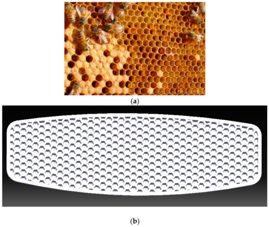
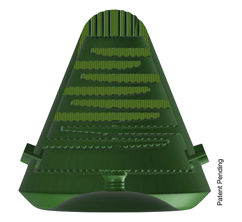
(a) A natural honeycomb structure; (b) the designed honeycomb core inspired by nature.

3D printing has often been used in the sports field, but in previous studies about 3D printed boards, researchers mainly focused on the geometry, only making small modifications to the equipment. This research team actually introduced different patterns to use as the board’s internal core structure. FDM technology and PLA materials were used to make the first sample board, featuring a uniform honeycomb structure that was created with the help of CATIA V5 software.

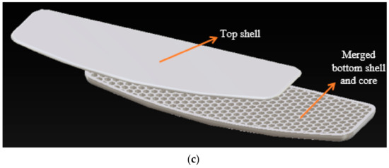
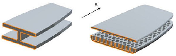
Most modern boards feature a sandwich structure, where a thin outer shell covers an inner core made of foam, which allows for increased buoyancy and stability, less weight, and improved bending resistance. These structures typically feature a top shell, the lightweight core, and a bottom shell, but this board merged the bottom shell with the core.

“A smaller scale version of a real on-water sports board was designed,” the researchers wrote. “The board had a 48 mm width and 144 mm length with a 357 mm radius curvature at two sides. A bottom curvature of 600 mm was considered, resulting in a model closer to the real one. The hexagonal honeycomb structure formed the core of the board, and was repeated across the specimen.”

The honeycombs were 3 mm wide, and patterned with 1 mm thick walls, while the bottom and top shells had thicknesses of 5 and 1.5 mm, respectively. The team used an XYZprinting da Vinci 1.0 Pro 3D printer to make the sample board with a uniform honeycomb structure.

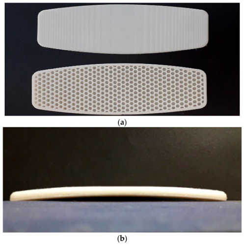
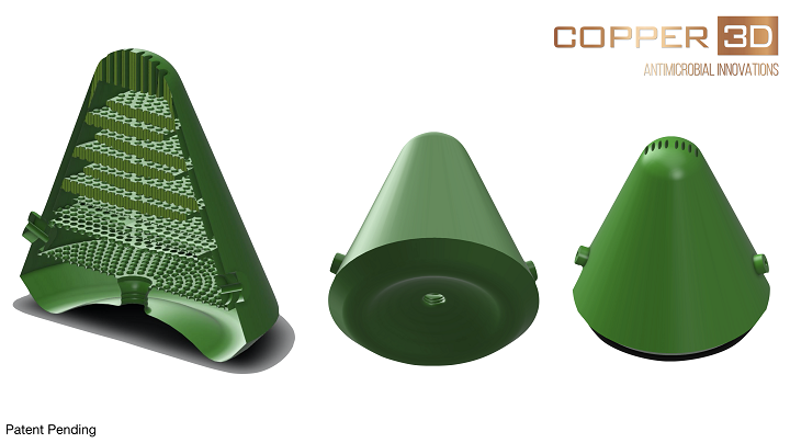
(a) Two separate 3D printed parts of the board; (b) two parts glued together with strong adhesive.

Surfboard fractures frequently happen between the surfer’s feet, in the board’s middle section. Usually, this occurs because the lip of the wave impacts in the middle and rips it into two parts after the surfer falls into the water, or because the surfer’s feet get too close together and concentrate their body’s pressure in the middle.

“In both of these circumstances, an immense force acts upon the middle portion of the board, causing large bending stress that may result in breakage,” the researchers explained.

“As both of these breakages are caused by bending stresses, a mechanical three-point bending test could be employed to determine the strength of the board in such loading.”

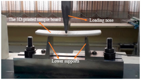
The board with a uniform honeycomb structure core under three-point bending test.

The team tested the honeycomb board under 3-point loading, though they had to change the grippers for the test.

“The test with the strain rate of 0.001 s1 was carried out at room temperature with an 80 mm distance between two supports. A displacement-controlled test was conducted to get a maximum deflection of 4 mm in the elastic range.”

I-shaped beam and the board with equivalent sections shown with orange lines.

In order to validate these results, and model the structure’s deformation under the test, the researchers developed a “geometrically linear analytical method,” using an equivalent I-shaped section with geometrical stiffness varied along the X-axis, to simulate the honeycomb structure. Then, a geometrically non-linear finite element method, based on ABAQUS software, simulated the boards with a variety of different core structures under the three-point bending test.

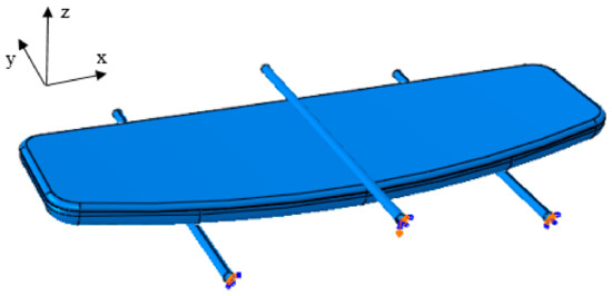
Boundary conditions of the finite element method model.

A bending test was simulated to validate the FEM model, and the team performed a mesh sensitivity analysis to make sure the numerical results were accurate. Then, they applied the same test to the sample board with the honeycomb core for a 4 mm maximum deflection. The maximum stress of ∼40 MPa, found in the middle of the board, was low enough to keep the board “in the desired elastic region.” For comparison, the PLA had a yield test level of 60 MPa.

Von Mises stress contour of the board with the uniform honeycomb core.

“The force–deflection curve for the experimental, geometrically non-linear numerical, and geometrically linear analytical results are plotted and compared to each other in Figure 13,” the researchers explained. “The preliminary conclusion drawn from this figure is the fact that the PLA board shows a linear elastic deformation up to 300 N force, beyond which the material yields, followed by plastic deformation that is manifested as a plateau after 500 N.”

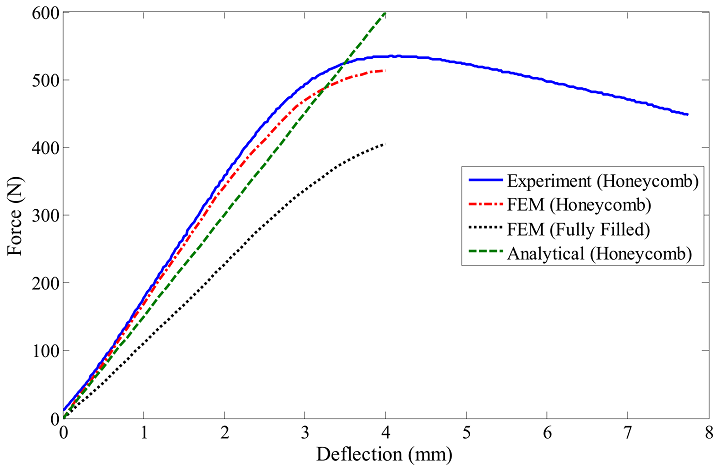
Comparison of the experimental, numerical, and analytical load–deflection curves for the three-point bending test of the honeycomb and fully-filled boards.

Once the team had validated the geometrically non-linear FEM model for the board with the honeycomb core structure, they simulated other patterns for the bottom shell’s core. Performing the three-point bending test with the geometrically non-linear FEM software package ABAQUS, while the board’s total volume was kept constant, helped them find the structure with the maximal bending resistance. The different structures they tested were:

  • Hexagonal-Rhomic (HR) Structure
  • Triangular Honeycomb Structure
  • Hexagonal Carbon Lattice
  • Pine Cone and Sunflower-Inspired Patterns
  • Spiderweb-Inspired Pattern
  • Functionally Graded (FG) Honeycomb Structure

“For all of the structures, the mesh convergence study was conducted and the appropriate number of elements for the FEM model was selected,” the researchers wrote. “Furthermore, the maximum stresses of all boards with various core structures were figured to have shown a maximum stress lower than the yield stress of the PLA material.”

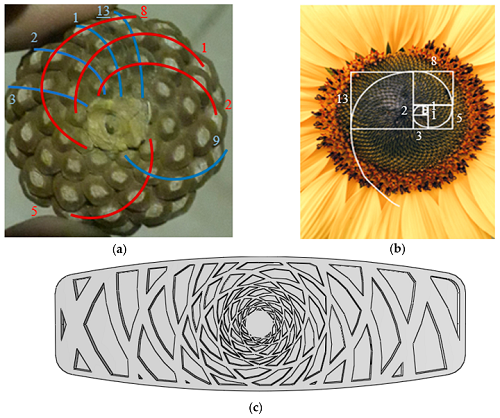
(a) A pinecone with two 8-number and 13-number opposite directional spirals; (b) Sunflower with Fibonacci spiral; (c) Pinecone-inspired structure designed using Fibonacci spirals.

They found that the board with the FG honeycomb structure had the best bending performance – 31% better, in fact, than the board with the uniform honeycomb structure at 500 N force. This means that it can tolerate maximum forces, as opposed to an intermediate force like the rest of the structures.

“Due to the absence of similar designs and results in the literature, this paper is expected to advance the state of the art of on-water sports boards and provide designers with structures that could enhance the performance of sports equipment,” the researchers concluded.

Discuss this  and other 3D printing topics at 3DPrintBoard.com or share your thoughts below.

The post 3D Printed Surfboard: Researchers Test Different Bio-Inspired Core Structures appeared first on 3DPrint.com | The Voice of 3D Printing / Additive Manufacturing.

UNO Researchers Looking for Study Participants to Test 3D Printed Prosthetic Arms

It’s necessary to perform studies on medical devices, 3D printed or otherwise, to make sure they’re working the way they’re supposed to be. Some examples we’ve heard about include: a Virginia Tech researcher used sensors to compile data about how well 3D printed amniotic band prosthetics were performing, researchers from TU Delft evaluated the level of functionality for a 3D printed hand prosthetic, and a team from the University of Nebraska at Omaha (UNO) investigated how a 3D printed partial finger prosthesis changed the patient’s quality of life. Now, UNO researchers have received funding to study how the brain adapts to using 3D printed prosthetic limbs, and they’re looking for research volunteers.

Rue Gillespie has a cap fitted to her head at the labs in the Biomechanics Research Building on Tuesday, Dec. 17, 2019, in Omaha, Nebraska. The cap was used to help read her brain’s activity as she performs tasks with her right arm and her 3D printed prosthetic arm.

The team was given a Research Project Grant (R01) from the National Institutes of Health (NIH), which will fund its investigation into changes in neural activity of children who have been regularly using a 3D printed prosthetic arm. The researchers need 40 children, between the ages of 3 and 17, with upper limb differences caused by Amniotic Band Syndrome or other congenital differences, to participate in the study, and e-NABLE is helping them get the word out.

Jorge M. Zuniga, PhD, takes photographs of Rue Gillespie’s arms during a visit to the labs at the Biomechanics Research Building.

Jorge Zuniga, PhD, a UNO associate professor of biomechanics, said, “Essentially what we’ll do with this research study is to try and look at their brain and see how the brain of young children adapt to the use of our prosthesis.”

Zuniga, who designed the Cyborg Beast prosthetic hand for e-NABLE, and Brian Knarr, PhD, another biomechanics associate professor at UNO, are the co-principal investigators for this study, which is building on Zuniga’s prior research to design and produce more affordable 3D printable prosthetic arms for children.

Most typical prosthetic limbs generally cost between $4,000-$20,000, but a children’s prosthesis can be 3D printed and constructed for much less – as little as $50. This lower cost is very helpful, as kids can quickly outgrow, or damage, their prostheses. 3D printing can ensure easy replacement, which in turn helps the children who need them feel more normal.

Jorge M. Zuniga, PhD, measures Rue Gillespie’s arm as her mother Holly holds her during a visit to the labs at the Biomechanics Research Building.

Zuniga explained, “What we do here is basically provide child-friendly prosthetic devices to children that are born without a limb or lose a limb due to an accident.”

Rue Gillespie participates in tests at the labs in the Biomechanics Research Building. To the right is certified hand therapist Jean M. Peck, left. The researchers were looking at the activity in Rue’s brain as she uses her prosthetic arm, which was 3D printed at the lab.

If you know of a child who might be interested and is able to participate in this UNO study, or if you just want more information about the research, email Zuniga at: jmzuniga@unomaha.edu.

So, how do you know if a child qualifies for this important study? First, they have to be between 3 and 17 years of age, with congenital upper limb reductions of the hand (partial hand) or arm (trans-radial). They must not have any musculoskeletal injuries in the upper limbs or skin abrasions, and participants with normal upper limb function have to be able to complete the tests. Finally, they need to be able to travel to the university from any domestic destination.

Rue Gillespie wears a cap fitted to her head at the labs in the Biomechanics Research Building, which was used to help read her brain’s activity as she performs tasks with her right arm and her 3D printed prosthetic arm.

Children who are chosen to be study participants will need to visit the laboratory in the Biomechanics Research Building at the university, accompanied by a parent, on two different occasions eight weeks apart. Zuniga and the research team will provide participants with a 3D printed prosthesis to keep, and between the visits, the child will have to perform several games using the prosthesis. During the visits, they will be asked to wear it and take part in different games, like moving toys or blocks around, while also wearing a cap with attached sensors so their brain activity can be measured. Additionally, multiple measurements of the child’s arms will be taken.

Jorge M. Zuniga, PhD, helps Rue Gillespie put on her prosthesis before she is run through a series of tests on Wednesday, Jan. 15, 2020, in Omaha, Nebraska, at the Gillespie home.

Participants and their families will receive the 3D printed prosthesis at no cost, and will also be provided with a small stipend for participating. Their travel arrangements, transportation, and hotel accommodations – from any domestic destination – will also be covered.

What do you think about this study? Discuss this story and other 3D printing topics at 3DPrintBoard.com or share your thoughts in the Facebook comments below.

(Source: e-NABLE)

The post UNO Researchers Looking for Study Participants to Test 3D Printed Prosthetic Arms appeared first on 3DPrint.com | The Voice of 3D Printing / Additive Manufacturing.

Copper3D Antimicrobial Filament Device Attempts To Reduce HIV Transmission From Breastfeeding

3D printing startup Copper3D, based in Chile and the US, uses nano-copper additives, and adds antimicrobial properties to polymers like PLA and TPU to create antibacterial 3D printed objects. Last year, Copper3D partnered with NASA to study microbial risks in outer space, but now the startup is working on an important project that’s a little closer to home.

According to UNICEF, the number of children and adolescents living with HIV in 2017 reached 3 million, with 430,000 newly infected people and 130,000 deaths from AIDS-related causes. UNAIDS reports that in 2018, 26,000 new HIV infections among children up to the age of 14 resulted from withdrawal of treatment during pregnancy, and breastfeeding. But even with this knowledge, the World Health Organization reports that 37.9 million people around the world were living with HIV at the end of 2018, 8.1 million of which didn’t even know they had the disease to begin with.

Companies and scientists around the globe are working to use technology to help control dangerous bacteria and viruses with high replication rates, like HIV. Copper3D has created a 3D printed device, with its copper nanotechnology, that can effectively inactivate the HIV virus under the right conditions on certain objects- a project that the startup’s Director of Innovation Daniel Martínez tells us is “the result of more than one year of research in antimicrobial polymers and the role on inactivating high replication rate viruses like HIV.”

Dr. Claudia Soto, Copper3D’s Medical Director, said, “Understanding the global problem behind the HIV statistics and analyzing the role that our antimicrobial materials could have in containing the transmission of HIV virus led us think that we could develop some kind of device that acts like an interface between mother and child to prevent the spread of this virus through breastfeeding, which is one of the main routes of infection.

“The initial idea is based on some of the few available studies that establish that copper based additives and filters can inactivate HIV virus in a solution of breastmilk, acting specifically against the protease (essential for viral replication) where copper ions non-specifically degrade the virus phospholipidic plasmatic membrane and denaturalize its nucleic acids; nevertheless, several issues such as toxicity levels, milk nutritional degradation, time for virus inactivation, or the optimal size/form of these filters remain unsolved.”

3D concept of the Viral Inactivator (patent pending)

Copper3D, led by co-founders Martínez, Dr. Soto, and CEO Andrés Acuña, began work on a project with, as the startup stated in a release sent to 3DPrint.com, “two lines of research.” Last year, they submitted a patent application for the project, called Viral Inactivation System for a Breastmilk Shield to Prevent Mother-to-Child Transmission of HIV. First, the viral inactivation effectiveness of its PLACTIVE material was tested with samples of HIV-infected breast milk, and then the team designed an object that optimizes the “viral inactivation of HIV” in the milk, acting as a mother-to-child interface during breastfeeding.

“Our purpose as a company has always been related to make a global impact through innovation in materials and nanotechnology. This line of research of active/antimicrobial medical devices and applications that opens with these studies, fills us with pride as a company. We believe that we are marking a before and after in the industry and we take this honor with a great sense of responsibility,” stated Acuña. “We will continue on the path of applied innovation, always thinking of playing an important role in the most urgent global healthcare challenges, where our antimicrobial materials, intelligent 3D designs, rigorous processes of technical validations and laboratory certifications, can generate a new category of antimicrobial/active devices that can avoid infections at a global scale and save millions of lives.”

Virology Laboratory at Hospital Clínico Universidad de Chile

The startup commissioned a proof-of-concept laboratory study at the Hospital Clínico Universidad de Chile’s Virology Laboratory to validate PLACTIVE’s potential HIV viral inactivation capacity. The study used a split-sample protocol to test and treat 20 sub-samples of HIV-1 (subtype B, cultivated from infectious clone NL4-3, with CXCR4 co- receptor).

The sub-samples were randomized into different groups: A, B, and Control. Samples for A and B were placed in either a green or blue 3D printed box, with and without the nano-copper additive; for a proper blind study, the researchers did not know which was which. The samples were exposed to the medical device for 15, 60, 120, and 900 seconds, and then cultured with HIV-1 Jukat reporter cells LTR-luciferase Cells (1G5); Copper3D performed culture measures on the samples 24, 48, 72, and 96 hours post-treatment.

“The preliminary results showed a reduction of viral replication up to of 58.6% by simply exposition of the samples to the 3D printed boxes containing copper nanoparticles. Fifteen (15) seconds of exposition were enough to achieve such a reduction. These data allow us to infer that by increasing the contact surface by a factor of 10X, we could obtain much higher inactivation rates, very close to 100% (log3) and according to our calculations, most probably in less than 5 seconds,” explained Martínez. “These results are coherent with the hypothesized reduction times proposed by Borkow, et. al. To the best of our knowledge, this is the first essay aiming to study the inactivation of HIV virus by using this new kind of polymers with antimicrobial copper nanotechnology in 3D printed objects.”

3D model of the Viral Inactivator (patent pending)

These results are pretty promising, which bolstered the team as they moved on to the second part of the study – designing a device, with a surface of contact expanded 10X, for HIV-contaminated milk, that’s embedded in nano-copper for use during breastfeeding.

“Like any innovation project, this is a constantly evolving process. We have learned a lot along the way, and we will continue designing, iterating, testing, validating and learning about antimicrobial materials and devices in the future. The preliminary results obtained in the first phase of our investigation with viral inactivation on active/antimicrobial nanocomposites materials gives us a great drive to continue in that line of research,” said Martínez. “We hope in the coming months to conclude the second phase of this study. For these purposes we develop a new antimicrobial flexible TPU based material (MDflex), with the same nanocopper additive as PLACTIVE, to test with new iterations of the design of this viral inactivation device with expanded surfaces of contact that we believe will be much more effective. These new insights will allow the development of a whole new range of active medical devices and applications, with incredible capabilities to interact with the environment, eliminating dangerous bacteria and viruses and protecting patients and users around the globe. This second and final phase of the study will be concluded in Q2 of 2020.”

Copper3D’s concept for its Viral Inactivator is to study how the antimicrobial capacity of its nano-copper materials impacts HIV inactivation, and how different shapes and designs for the 3D printed device can increase the surface of contact with breast milk, while using the nano-copper to enhance effectiveness. The device was made with various layers and “rugosities” in order to imitate what has been observed in the human gastrointestinal tract.

Collaborators at the University of Nebraska at Omaha’s Department of Biomechanics will perform mechanical characterization testing of Copper3D’s prototype.

“Copper3D has once again disrupted the field of medical devices by creating this revolutionary device that can have a tremendous impact in reducing mother-to-child transmission of HIV,” said Jorge Zuniga PhD, Associate Professor of Biomechanics with the university. “Our laboratory is fortuned to partner with Copper3D, in such an impactful project.”

Concept of applications with the Viral Inactivator

Discuss this and other 3D printing topics at 3DPrintBoard.com or share your thoughts below.

The post Copper3D Antimicrobial Filament Device Attempts To Reduce HIV Transmission From Breastfeeding appeared first on 3DPrint.com | The Voice of 3D Printing / Additive Manufacturing.

Collaborative Research Team Creates 3D Printed Armor Inspired by Chiton Scales

From lobster claws and fish scales to conch shells, humans have often been inspired by nature in the creation of protective gear. Recently, a team of researchers hailing from MIT, Virginia Tech, Harvard University, California State University Fullerton, and the Max Planck Institute of Colloids & Interfaces published a paper, titled “Bioinspired design of flexible armor based on chiton scales,” about their work using multimaterial 3D printing and parametric computational modeling to create “a synthetic flexible scaled armor analogue” based on the scaled armors of chitons, a group of marine mollusks.

“This approach allows us to conduct a quantitative evaluation of our chiton-inspired armor to assess its orientation-dependent flexibility and protection capabilities,” the researchers wrote in the abstract.

Biological armor offers mechanical protection from the environment, which includes attacks from predators. Man-made armors use rigid structures for this protection, which the team explained can result “in a trade-off with flexibility and maneuverability.”

Rhyssoplax canariensis (Image: Jose Maria Hernandez Otero, BioLib)

“Many chiton species possess hundreds of small, mineralized scales arrayed on the soft girdle that surrounds their overlapping shell plates,” the abstract states. “Ensuring both flexibility for locomotion and protection of the underlying soft body, the scaled girdle is an excellent model for multifunctional armor design.”

Because many biological armors are based on hard and rigid armor plates, flexibility is tough to pair with it. Scale-like armors with many small, repeating elements, like that of chiton, can help maximize the combination of flexibility and protection. The team completed a study of the 3D geometry, interspecific structural diversity, material composition, and nanomechanical properties of chiton girdle scales, focusing on the chiton Rhyssoplax canariensis (Chitonidae: Chitoninae). This species is covered by a total of eight “bilaterally symmetrical overlapping mineralized shell plates,” in addition to the protective scaled girdle.

Figure 1. Biological flexible scaled armor in the girdle of the chiton Rhyssoplax canariensis. a, b Wide-field SEM images of the chiton R. canariensis, which show the dorsal and side view of the primary plates (PP) and peripheral scale-covered girdle (G), respectively. c Enlarged view of the girdle covered with dorsal scales. The image was acquired from the region indicated by the rectangular box in a, highlighting individual overlapping dorsal girdle scales, a fully covered protective armor. d Fractured cross-section of the girdle scaled armor, which consists of three components arranged from dorsal to ventral: (1) dorsal scales (DS); (2) fibrous layer (FL); and (3) ventral scales (VS). The white dashed lines indicate the height of the inter-scale organic matrix, and the red arrow indicates gaps between adjacent scales. e Cross-sectional view of scaled armor based on micro-computed tomography (μ-CT) data. Note the distance between the dorsal and ventral scale layers, which is occupied by the fibrous layer. f SEM image of the rod-shaped ventral scales, where the white arrows indicate small cracks.

“In contrast to most shelled mollusks where mobility is limited, as in the single shelled mollusks (gastropods, including snails, scaphopods or tusk shells, and some cephalopods such as Nautilus) or hinge-shelled bivalves (mussels, clams, scallops, etc.), most polyplacophorans (chitons) are characterized by eight overlapping, hard shell plates (Fig. 1a, b), which collectively accommodate a wide range of motion,” the researchers explained. “In addition to the eight overlapping shell plates (which are functionally analogous to the segmented plate-like exoskeleton of many crustaceans), additional protection is provided by a thick leathery girdle that skirts the animal’s periphery.”

Even though the girdle scales are nearly pure mineral and very rigid, they are also very flexible and able to conform to rough surfaces. Chiton scales are also more uniform in composition, with no porosity, sub-layering, or material heterogeneity.

“This observation underlines the suitability of chiton scales as a model for bioinspiration, as the mechanical performance of their armor can be ascribed primarily to geometric considerations, rather than fine scale material variation,” the team noted.

Figure 1. g–i: μ-CT 3D rendering of the chiton R. canariensis girdles in different viewing orientations and modes: g top view of girdle scales, h transparency mode showing the overlapping characteristics among adjacent scales, bottom view i with and j without ventral scales. Local coordinates: N (normal), from ventral to dorsal; R (radial), from proximal to distal; C (circumferential).

The team used many experimental and modeling approaches, such as mechanical testing, finite element modeling, electron microscopy, synchrotron X-ray micro-computed tomography, and instrumented nanoindentation, to investigate chitons, and the use of chiton-like scales in 3D printed flexible armor.

“Incorporating the physical and functional properties of chiton girdle scales characterized in these investigations, we design a bio-inspired flexible armor system, integrating parametric geometrical modeling and multi-material 3D printing,” the researchers wrote. “We explore the functional trade-offs between protection and flexibility in this model scaled armor system and its potential for informing the design of additional functional prototypes.”

A Connex 500 multi-material 3D printer from Stratasys was used to create prototypes out of both flexible and rigid photopolymers in different colors.

3D geometry and surface morphology of individual dorsal scales of the chiton R. canariensis. a–f: μ-CT data-based 3D rendering of individual girdle scales in different view angles and modes: a front view, b top view (yellow arrows indicate pore openings), c bottom view (white arrow shows a depression at the base of the scale), d two side-views (white arrows shows the surface roughness at the lower surface of backside), e back view, and f transparent mode (the yellow arrows show holes in the dorsal surface of scales and the white arrow indicates depression in base). g Projection contours along two orientations (transverse and bottom) are used to describe the geometries of chiton scales. h Top view of a μ-CT data-based reconstruction of the girdle scale assembly of R. canariensis. Three columns of scales used in the geometrical measurement are highlighted in pink color and their positions are indicated. i Variations of geometrical parameters as a function of scale position. The solid line represents the average and the shaded area shows the standard deviation. j SEM image of a scale’s back surface. k Magnified-view of scale surface with microscopic bumps at the underside of the back surfaces of chiton scales, as indicated by the white box in j. l SEM-derived stereographic reconstruction of microscopic bumps in a similar region shown in k. m Backscattered SEM image of a polished cross-section in the region of microscopic bumps of a scale, highlighting the difference in morphology between the front and back surfaces of the dorsal scales.

“In order to successfully mimic scale morphology for the production of a 3D-printed structural analogue…quantitative measurements of the scale geometry were conducted by defining several morphometric parameters,” the researchers stated.

The team also took “3D morphometric measurements” of the dorsal girdle scales from chiton species in the Ischnochitonidae and Chitonidae families. In order to reproduce the morphometrics for further modeling of scaled arrays, they created a parametric geometrical model.

“The successful 3D modeling of individual scales allowed us to design a composite scale armor assembly similar to that of chitons,” the team explained. “The bio-inspired armor system included rigid scales embedded in an underlying soft substrate.”

Figure 5. 3D parametric modeling of chiton scale geometries. a Top, the 3D scale model with three principal scaffolding curves. Bottom, 3D scale model highlighted with the central spine for generating the surface meshes. b Three principal curves with geometrical landmarks indicated. c, d Comparison of original chiton scales with corresponding mimicked scale models for two species: c, a single-curved scale from Rhyssoplax canariensis and d, a double-curved scale from Lepidozona mertensii.

They used materials with moduli of ca. 2 GPa and ca. 0.7 MPa, respectively, to 3D print the scales and matrix, in order to properly replicate how the scales would interact with soft girdle tissue. The scale assembly was very flexible, with a similar range of motion to real chiton scales, and the team was able to efficiently explore a variety of arrangements with the scales due to the “parametric nature of our model.”

Design and fabrication of bio-inspired flexible scaled armor. a Schematic diagram showing basic components of the armor; (1) scales, (2) matrix, and (3) soft underlying layer. b Side and c bottom view of the armor. d, inter-scale spacing. d Flat panel with uniform scales fabricated through additive manufacturing. e A bent panel showing excellent flexibility. f, g Design of scale pattern with size gradients. h Scale assembly in flat and curved substrate. i Scale assembly on double-curved surfaces. j X-ray projection images of a kneepad based on the bio-inspired scaled protective panel in j extended and k bent positions, demonstrating its conformability and flexibility. l Demonstration of the protection capability of the chiton scale-inspired kneepad on broken glass.

They also studied the mechanical performance of their multimaterial 3D printed prototypes, and even 3D printed a scaled kneepad prototype in order to demonstrate the usefulness of the chiton-inspired system for both protective and flexible applications.

“Current kneepad designs often fall in one of two extremes: hard and rigid plates that create heavy protection but limit flexibility, or elastomeric rubbers/foams that provide high flexibility but limited protection (especially against sharp objects). The chiton scale-inspired knee protection pad offers a unique solution to this dilemma,” the researchers noted.

The 3D printed scale assemblies had much higher puncture resistance than typical kneepads with rubber- or foam-based inserts, and also featured good shape-conforming capabilities in extended and bent configurations.

Co-authors of the paper are Matthew Connors, Ting Yang, Ahmed Hosny, Zhifei Deng, Fatemeh Yazdandoost, Hajar Massaadi, Douglas Eernisse, Reza Mirzaeifar, Mason N. Dean, James C. Weaver, Christine Ortiz, and Ling Li.

Discuss this and other 3D printing topics at 3DPrintBoard.com or share your thoughts below. 

The post Collaborative Research Team Creates 3D Printed Armor Inspired by Chiton Scales appeared first on 3DPrint.com | The Voice of 3D Printing / Additive Manufacturing.

Researchers Evaluate Comfort and Stability of 3D Printed Applicators for Oral Cancer Therapy

Oral cancer is on the rise around the world, and it’s especially bad in developing countries, such as Pakistan, Sri Lanka, and India, which don’t have the necessary medical infrastructure for early detection and treatment. A team of researchers from Boston and India explained in their paper, “Platform for ergonomic intraoral photodynamic therapy using low-cost, modular 3D-printed components: Design, comfort and clinical evaluation,” that there is “critical demand for an effective treatment modality that can be transparently adapted to low-resource settings.”

“The high expense and logistical barriers to obtaining treatment with surgery, radiotherapy and chemotherapy often result in progression to unmanageable late stage disease with high morbidity. Even when curative, these approaches can be cosmetically and functionally disfiguring with extensive side effects. An alternate effective therapy for oral cancer is a light based spatially-targeted cytotoxic therapy called photodynamic therapy (PDT),” the researchers wrote.

PDT uses a photosensitizer molecule accumulated in the tumor, and once it interacts with a specific light wavelength, it can cause targeted damage. It has few side effects, doesn’t cause disfigurement or loss of sensation, and has shown some good clinical results in terms of good post-treatment healing and epithelial necrosis. For regions with fewer medical resources, it would be very helpful to translate PDT therapy so it can be completed in an outpatient visit, and 3D printed oral applicators would be a great help on this journey.

“Despite excellent healing of the oral mucosa in PDT, a lack of robust enabling technology for intraoral light delivery has limited its broader implementation,” the team continued in their paper.

“Leveraging advances in 3D printing, we have developed an intraoral light delivery system consisting of modular 3D printed light applicators with pre-calibrated dosimetry and mouth props that can be utilized to perform PDT in conscious subjects without the need of extensive infrastructure or manual positioning of an optical fiber.”

The team’s goal in this study was to evaluate the clinical utility and ergonomics of their 3D printed oral PDT applicators, which were designed to comfortably, and stably, deliver light to patients’ oral lesions.

“Here, the natural structure of the patients’ oral cavity, teeth and jaw provided the support and stability to hold the fiber in place, avoiding any use of posts, holders, reflectors or light pipes,” the researchers explained.

3D Schematics of the applicators for three different regions in the mouth. The photos showcase the integrated unit with the applicator (1), the bite wing (2) and the endoscope (3) utilized in the ergonomics clinical study.

The 3D printed intraoral applicators, which attach to the optical fiber, have two parts – bite blocks and applicators. The blocks position the angle of the applicator, which then delivers the suitable beam spot, along with pre-calibrated dosimetry, to a certain lesion size. The team used Autodesk Fusion 360 to design the light applicators, and they were printed on a Stratasys Objet Pro system out of VeroBlue and VeroBlack filament.

Photograph of the oral cavity with ink marks in three points tested in the ergonomics study.

In order to determine how stable and comfortable the applicators were, the researchers performed a study, approved by the Massachusetts General Hospital Partners Institution Review Board, on ten subjects.

A physician placed three fiducial ink marks on each subject’s inner cheek, and tested the anterior and posterior buccal cheek and retromolar positions for ten minutes, one after the other. The light delivery fiber was replaced with an endoscope of similar size, with a 5.5 mm diameter camera and 6 LEDs, in order to record motion at these three spots.

The researchers explained, “Subjects were asked to rate comfort and fatigue on a numerical scale of 1 to 5 where 1 was no discomfort due to the applicator and 5 was intolerable discomfort due to the applicator.”

Each subject was asked three questions:

  1. Was there any physical discomfort during the ten minutes?
  2. Rate the fatigue or numbness in your mouth.
  3. Would you be comfortable immediately repeating another ten-minute interval at the same site?

Flow chart of video and image processing method to calculate centroid of the fiducial ink mark mimicking the anterior buccal cheek, posterior buccal cheek or retromolar position imaged with a USB Endoscope fitted to the oral applicators.

Additionally, the endoscope actually recorded the movement of the ink marks during testing in order to evaluate the applicators’ stability. Custom-designed algorithms in MATLAB were used to process the videos. They determined that the applicators were indeed stable, and capable of “delivering light precisely to the target location in ten healthy volunteers.” Additionally, the ten subjects rated the devices overall as comfortable, though one did report “no tolerance” to the applicator in the posterior buccal cheek position.

Five of the subjects had confirmed T1N0M0 oral cancer lesions with no lymph node involvement, and several months after PDT treatment, demonstrated no cancerous lesions, fibrosis, or scarring. This showed that the 3D printed applicators, paired with an inexpensive fiber and LED-based light source, “served as a complete platform for intraoral light delivery achieving complete tumor response with no residual disease at initial histopathology follow up in these patients.”

“While we used a set of applicators with pre-determined sizes that were comfortable for various subjects, mouth and jaw dimensions and genders, it is reasonable to envision extension of this approach to customized patient treatment. Specifically, personalized applicators can be rapidly printed at the time of procedure due to advances in image-based 3D printing and the increasing availability of low-cost, high-quality 3D printers in clinical settings,” the researchers concluded.

“The ergonomic design of 3D printable light applicators has significant practical benefit in enabling longer irradiation duration and improved accuracy of light delivery necessary for curative PDT. With costs of healthcare and cancer incidences increasing worldwide, particularly in developing countries, we report an affordable methodology for delivering light stably and ergonomically in the oral cavity which can be used in conjunction with a low-cost, portable, battery-powered fiber-coupled LED based light source.”

This is just one more good example of 3D printing successfully being used for cancer therapy.

Co-authors of the paper are Srivalleesha Mallidi, Amjad P. Khan, Hui Liu, Liam Daly, Grant Rudd, Paola Leon, Shakir Khan, Bilal M. A. Hussain, Syed A. Hasan, Shahid A. Siddique, Kafil Akhtar, Meredith August, Maria Troulis, Filip Cuckov, Jonathan P. Celli, and Tayyaba Hasan.

Discuss this and other 3D printing topics at 3DPrintBoard.com or share your thoughts below. 

The post Researchers Evaluate Comfort and Stability of 3D Printed Applicators for Oral Cancer Therapy appeared first on 3DPrint.com | The Voice of 3D Printing / Additive Manufacturing.

Evaluating the Performance of 3D Printed Foot Orthoses for People with Flat Feet

People with conditions such as flat feet often turn to custom foot orthoses (FOs), which can be fabricated using 3D printing and scanning technologies at a reduced cost in less time. A team of researchers from Taiwan recently conducted a study, titled “Biomechanical Evaluation and Strength Test of 3D-Printed Foot Orthoses,” in order to evaluate the use of 3D printed FOs by people with flat feet.

“The purposes of this study were to fabricate FOs using low-cost 3D printing techniques and evaluate the mechanical properties and biomechanical effects of the 3D-printed FOs in individuals with flexible flatfoot,” the researchers wrote.

Figure 1: Fabrication of the 3D printed FOs. (c) Extraction of the FO shape from the foot model. (d) Solid FO model imported into Cura to be sliced and output as G-Code.

They 3D printed 18 FO samples, at orientations of 0°, 45°, and 90°, and subjected them to human motion analysis, with 12 flatfooted individuals, as well as mechanical testing to determine their maximum compressive load and stiffness.

The researchers 3D scanned the participants’ feet, and exported the result as an STL file, which was edited with Autodesk Meshmixer software and 3D printed out of PLA filament on an Infinity X1 FDM 3D printer. The build parameters of the FOs were defined using Ultimaker Cura 3.3 software.

“Because no standard tests for FOs exist, we designed a procedure to test the stiffness of the FOs,” the researchers explained. “A rectangular fixture measuring was placed on the lateral side of each FO.”

Then, six 3D printed FOs for each build orientation were put through dynamic compression, and the team collected displacement and reaction force data. An ANOVA, or one-way analysis of variance, test, and a post hoc Tukey’s test, were also completed in order to compare the maximum compressive load and stiffness of the FOs.

(e) FO 3D printed using an Infinity X1 3D printer. (f) Top view and (g) rear view of the 3D printed FO.

“The executed compressive tests revealed that the 45° and 90° build orientations engendered similar load and displacement behaviors in the FOs when the displacement was less than 5 mm,” they wrote. “The ANOVA revealed differences between groups. The Tukey test demonstrated that the maximum load in the FOs fabricated using the 45° build orientation ( N) was significantly greater than those in the FOs fabricated using the 90° ( N) and 0° ( N) build orientations.”

The participants were also subjected to a motion capture experiment, where both kinematic and kinetic data were collected by an eight-camera 3D Vicon motion analysis system. They had to “perform five trials of level walking at a self-selected speed” wearing standard shoes, and then the shoes embedded with 3D printed FOs.

The team again performed an ANOVA test to compare mechanical parameters of the FOs from each of the three build orientations; a paired-sample test was also conducted in order to compare biomechanical variables from the motion capture tests.

“The results indicated that the 45° build orientation produced the strongest FOs. In addition, the maximum ankle evertor and external rotator moments under the Shoe+FO condition were significantly reduced by 35% and 16%, respectively, but the maximum ankle plantar flexor moments increased by 3%, compared with the Shoe condition. No significant difference in ground reaction force was observed between the two conditions,” the researchers wrote. “This study demonstrated that 3D-printed FOs could alter the ankle joint moments during gait.

“We can conclude that the low-cost 3D printing technology has the capability of fabricating custom FOs with sufficient support to correct foot abnormalities. We provide evidence that such FOs engender biomechanical changes and positively influence individuals with flexible flatfoot.”

Co-authors of the paper were Kuang-Wei LinChia-Jung HuWen-Wen YangLi-Wei ChouShun-Hwa WeiChen-Sheng Chen, and Pi-Chang Sun.

What do you think about this news? Discuss this story and other 3D printing topics at 3DPrintBoard.com or share your thoughts in the Facebook comments below. 

The post Evaluating the Performance of 3D Printed Foot Orthoses for People with Flat Feet appeared first on 3DPrint.com | The Voice of 3D Printing / Additive Manufacturing.

Silk Fibroin-Reinforced PLA to Make 3D Printed Interlocking Nail for Fracture Healing

A diaphyseal fracture is a common break that occurs along the shaft of a long bone, like the femur, and can be treated with interlocking nails, which are inserted in the bone and transfixed by screws at the ends. But these eventually need to be removed because of complications that can occur when the nails have been implanted for a long time, such as materials like stainless steel not providing a good biological environment for cells.

Researchers S. PitjamitK. ThunsiriW. Nakkiew, and P. Pothacharoen from the Chiang Mai University in Thailand published a paper, titled “Preparation and characterization of silk fibroin from four different species of Thai-local silk cocoon for Bone implanted applications,” about their work using PLA, reinforced with locally sourced silk fibroin material, to 3D print a biocomposite interlocking nail.

Silk may look and feel soft, but the protein fiber is made of 75% biocompatible fibroin, a strong, insoluble material that has multiple applications in the medical field, including sutures, wound healing, and tissue engineering.

“Previous studies have proved that fibroin has good biological and mechanical properties such as biocompatibility, biodegradability, water permeability, non-cytotoxicity and the strength and resiliency of silk fibers,” the researchers wrote. “Silk fibers has an ultimate tensile strength 740 MPa while collagen and polylactic acid has an ultimate tensile strength only 0.9 to 7.4 and 28 to 50 MPa, respectively.”

The team chose four species of local Thai Bombyx mori silk cocoons from which to extract silk fibroin: Nangnoi Srisaket-I (NN), Nanglai (NL), Luang Saraburi (LS), and J108. They cut the cocoons into small pieces, which were then degummed, rinsed, and dried for 24 hours, before being dissolved in a solvent.

The resulting solution was soaked in DI water for three days, with the water changed daily, and then the dialyzed silk solution was filtered and frozen. Finally, in order to create sponges, the frozen solution was lyophilized (freeze-dried).

“After the extraction, fibroins of each silk cocoon species were characterized and compared the physical property by using Scanning Electron Microscopy (SEM), Energy Dispersive X-ray (EDS) and Fourier Transform Infrared Spectroscopy (FT-IR),” the researchers wrote. “Then, the biological test was performed on cell viability and cytotoxicity with human fetal osteoblast cell line.”

The researchers investigated the “conformations of fibroin protein in regenerated each silk scaffolds” using FTIR spectroscopy, and each species showed typical random coil structures and Beta-sheet structures. SEM and EDS tests showed that each of the silk fibroin species had interconnected pores, at an average size of 10-60 microns.

“As shown in Figure 4, silk fibroin weight percentage consist of Carbon (C), Nitrogen (N) and Oxygen (O) element only which symbolize the proteinaceous compounds originating from Silk Bombyx mori,” the team wrote.

Finally, an Alamar blue assay was performed on the four species of silk fibroin solutions, in order to observe cell viability and confirm that they weren’t toxic.

“The comparison of each silk species with control presented that cell viability percentage all scaffolds were not significantly the control (p-value> 0.05) as shown in Figure 5,” the researchers stated.

The results of this test showed that they all had non-cytotoxicity, which means they can be safely used in animal and human bodies.

“The best silk species from biological performance will be used to reinforce PLA interlocking nails using 3DP process in the future study,” the team concluded. “From the result, all of local silk cocoons species present non-cytotoxicity ability which can be used in human or animal body without endangerment. For future work, bio-composite filament for 3DP from silk fibroin reinforcing PLA will be tested and observed the other abilities such as cell proliferation ability, mechanical properties and printing morphology.”

Discuss this research and other 3D printing topics at 3DPrintBoard.com or share your thoughts in the Facebook comments below.

The post Silk Fibroin-Reinforced PLA to Make 3D Printed Interlocking Nail for Fracture Healing appeared first on 3DPrint.com | The Voice of 3D Printing / Additive Manufacturing.

VELO3D Releases Assure for 3D Metal Printing: Stratasys Direct Manufacturing as First Customer

With the release of the VELO3D Assure™ Quality Assurance and Control System for its Sapphire® 3D metal printers, VELO3D also brings on board a heavy hitter in their first customer as Stratasys Direct Manufacturing, a subsidiary of Stratasys, Ltd., will be the first to integrate Assure into their manufacturing processes.

VELO3D’s Assure™ quality control dashboard enables engineers to track the quality and progress of Sapphire® machines in real-time.

Assure offers unprecedented monitoring and substantiation of part quality, offering the following features:

  • Detects process anomalies
  • Flags issues
  • Highlights necessary corrective actions
  • Offers traceability

“Assure is a revolutionary quality-control system, an inherent part of the VELO3D end-to-end manufacturing solution for serial production,” says Benny Buller, founder and CEO of VELO3D. “Assure is part of our vision to provide an integrated solution to produce parts by additive manufacturing with successful outcomes.”

Upon receipt of their own Sapphire 3D printer earlier this year, Stratasys Direct not only began using Assure, but they produced an entire study from their evaluation, which included:

  • Monitoring integrity of builds
  • Validating bulk material density
  • Observing ongoing process metrics
  • Verifying calibration of the system

Assure predicts defectivity as a function of layer number. An increase in the defectivity metric is correlated with increasing defectivity in the bulk core of the part.

Before and during a build, Assure validates that critical parameters stay within control limits ensuring high quality parts. Clicking on individual squares reveals details on the underlying event.

These results were published in ‘Stratasys Direct Manufacturing Performs Field Validation of VELO3D Assure™,’ after the Stratasys Direct team used Assure for 12 weeks, verifying findings produced by VELO3D. They are now using the system in ongoing production efforts.

“AM can print parts and meet requirements for single units but scaling from a single part into serial production has been challenging. OEMs lack confidence in AM process control, and AM users struggle to demonstrate it. Without visibility into each part’s deposition lifetime AM becomes a risk,” states author Andrew Carter, Sr. Manufacturing Engineer at Stratasys Direct Manufacturing.

Assure boosts manufacturing techniques for the user as they can understand tool health better, calculate part quality, and perform field validation. Engineers 3D printed test structures during their study, producing wedges measuring 20mm x 41mm in width and length respectively. The wedges could be stacked into a tower shape, making a structure to match the build z-height. For each test run, they created two towers.

Test structure added to production builds to enable destructive testing. Image from ‘Stratasys Direct Manufacturing Performs Field Validation of VELO3D Assure™.’

Ultimately, 75 test structures were created and then analyzed via X-rays. Bulk porosity measured at 0.02 percent, and the researchers pointed out that there was no ‘single part exhibiting porosity higher than 0.1 percent. There were no deviations in print quality for the test builds.

Bulk defectivity measured on test parts by x-ray imagery. Image from ‘Stratasys Direct Manufacturing Performs Field Validation of VELO3D Assure™

“Stratasys Direct has built a culture of continuous improvement that means we are continually setting new standards for our industry on quality,” said Kent Firestone, CEO of Stratasys Direct Manufacturing. “We integrated Assure into our quality control workflow because it produces highly actionable insights. The user interface features intuitive graphs and charts that enable us to see and interpret the vast amount of data collected during builds. This information helps our engineers verify the quality of the build each step of the way and enables them to make quick decisions in the event of an issue. Assure helps us reduce production variation, improve yields, and circumvent anomalies to ensure consistent additive manufacturing.”

If you are interested in finding out more about Assure, check out the webinar on November 14th at 10 am PST, offered by Stratasys Direct. Click here to register. Also, if you are attending formnext in Frankfurt, Germany, don’t miss the joint press conference at the VELO3D booth (Hall 11, E79) on November 19 at 10 a.m.

VELO3D continues to be a dynamic presence in the 3D printing realm, from fabrication of a supersonic flight demonstrator to their efforts to expand on design and build limitations. What do you think of this news? Let us know your thoughts! Join the discussion of this and other 3D printing topics at 3DPrintBoard.com.

Assure provides true z-height quantitative powder bed and part metrology. Note the sections of parts with red lobes indicating metal protruding >300um above the powder bed but still below control limits.

[Source / Images: VELO3D]

The post VELO3D Releases Assure for 3D Metal Printing: Stratasys Direct Manufacturing as First Customer appeared first on 3DPrint.com | The Voice of 3D Printing / Additive Manufacturing.

Romania: Comparing Additively and Conventionally Manufactured Patient-Specific Cranial Implants

A trio of researchers from Bucharest, Romania completed a multi-centre cohort study, entitled “3D patient specific implants for cranioplasty,” about 50 patients from 10 hospitals with a variety of cranial defects.

A cranioplasty is performed to repair these defects after congenital anomalies, growing skull fractures, surgical decompression, trauma, or tumor surgery, which can result in aesthetic, functional, and psychological implications. We’ve seen 3D printing used in this type of procedure before.

The abstract states, “In all patients the neurosurgeon repaired the cranial defect using 3D printed and CNC milling and drilling grafts or Patient Specific Implants, from two world known manufacturers, custom made in accordance with the data obtained from the patient’s 3D CT reconstruction.”

Of the 50 patients between 5-68 years old, 16 were female and 34 were male, while 22 were from urban areas and 28 from rural. 31 patients presented with trauma, while 16 were decompression and three had a tumor. The neurosurgeons used a scanning protocol, coupled with data from patients’ 3D CT reconstruction, to determine whether 3D printing or CAD-CAM manufacturing should be used to fabricate the patient-specific implants.

The procedure was the same for nearly all the cases – DICOM data files were collected, archived into a ZIP file, and sent in an encrypted message through a secure platform to keep the information confidential. Once the files are extracted, they’re verified to make sure the scan protocol was followed, and to see if they can be transformed to STL files in order to clearly see the bone defect and compare it “with standard anatomic models, with contra-lateral side of the same patient” in order to develop a 3D dynamic model of the cranium with the defects included.

“The 3D model (pdf file with 3D media option activated) is sent and presented by manufacturer directly to the surgeon with several comments regarding: surrounding soft tissue, sizes, distances, thickness and a lot of other parameters, including material together with an approval letter that has to be stamped and signed by the surgeon,” the researchers explained. “The surgeon will reply (in written) to the manufacturer with its comments regarding all of the above and in some steps will conclude if he agrees or not, on the proposed 3D model. If the response is affirmative and all legal and financial issues are agreed upon by all parts, the manufacturer will start to produce the implant, respecting all safety and regulations of EU, regarding Patient Specific Implants. That will be delivered in the country of the surgeon, directly to its hospital OR during a period of 5-15 days. In some emergency cases, the implant can be delivered within 48 hours, with a set of legal documents and a passport for the implant; the passport contains all of the important info that patient has to have, after surgery. If the Implant came unsterile and very well packaged, it will be sterilized to 134 °, 1-2 cicles 20 minutes, 24-48 hours prior the day of surgery.”

Surgeons used factors like anatomical area, risk of infection, and position and size of the defect to determine which material to use – 45 implants were made with PEEK, while four were created out of a titanium alloy and one was made from the ceramic glass material Bioverit. These same factors were taken into consideration when determining the best type of fixation system, such as bio-resorbable craniofix implants that use a special tool for anchoring and fixation, titanium holed plates, non-locking or locking screws, or non-resorbable sutures.

The presented case was for a 23-year-old female whose cranial trauma was caused by a car accident. Upon arrival, she had a Glasgow (coma state) score of 3 and intracranial pressure with a peak of 80 mmHg – the standard value is 20 mmHg. The surgeon observed a cerebral edema post-trauma malign, and chose to fix it using a cranial resection with dural plasty. Three days later, the surgeon performed “a large craniectomy FTPO (fontal-temporal-parietal-occipital) and dural plasty with temporal muscle and periosteum.” The cranioplasty was performed 44 days later.

FIGURE 3. CT scan images done respecting above scanning protocol.

The manufacturer received and analyzed the patient’s CT DICOM files, and created a 3D model that the surgeon then had to approve.

FIGURE 4. Presentation of 3D model proposed by manufacturer using Adobe Acrobat 3D pdf file where model can be visualized in motion. (A) right view with implant; (B) proposed model of implant; (C) left view; (D) frontal view with implant into defect; (E) right view without implant; (F) below view; (G) rear view with implant; (H) above view with implant in place.

“There are cases when CT DICOM files are rejected, because they are not done as required by the protocol and they are not accurate enough and cannot be used for 3D model and also for implant construction,” the researchers explained.

“A team of specialists in cranial reconstruction communicate to the surgeon (in writing): any possible complications, details regarding sizes of implants, remaining bone, distances and surrounding soft tissues, options for manufacturing materials, fixation systems (Titanium Alloy, Peek, Bioverit–ceramic glass) (9,10) to help him take the most efficient decision.”

The surgeon asked for the implant to be fabricated from PEEK-Optima, in case any intra-op adjustments were needed, and also requested 1 cm suture holes.

In this particular case, the patient-specific implant was not 3D printed; rather, CAD-CAM manufacturing was used.

“Regarding the general study: There were a total of 50 patients treated with Patient Specific Implant that proved significant aesthetic, functional and psychological improvements after the cranioplasty surgery,” the researchers explained. “Minor complications occurred in several cases, that were related to cranioplasty fixation systems and scalp complications (related to initial trauma), and two cases of wound infection (one related to the type of suture used and the otherwound contamination without suture defect). There were no fatalities and no long-term complications.”

The team concluded that a custom 3D printed patient-specific implant can result in better aesthetics and “good functional outcomes,” making this cranial reconstruction option “a safe and viable solution.”

FIGURE 6. Patient Specific Implant made from PEEK in protective case; (B) Inferior image of implant

“Nevertheless, the financial aspect of using such an implant is the main factor that negatively influences the addressability of such a technique to the general public,” the researchers wrote. “At this time Patient Specific Implants in Romania are paid by patients and are expensive, but very reliable and effective at the same time.”

Discuss this story and other 3D printing topics at 3DPrintBoard.com or share your thoughts in the Facebook comments below.

The post Romania: Comparing Additively and Conventionally Manufactured Patient-Specific Cranial Implants appeared first on 3DPrint.com | The Voice of 3D Printing / Additive Manufacturing.

4D Printed Shape Memory Polymers Given Better Performance & Recyclability

Authors Ang Li, Adithya Challapalli, and Guoqiang Li explore a trend that continues to grow: 4D printing. Their findings are explained in the recently published “4D Printing of Recyclable Lightweight Architectures Using High Recovery Stress Shape Memory Polymer.” Here, the benefits of smart materials that can adapt to their environment are explored as the researchers consider challenges in 3D printing self-healing shape memory polymer (SMP) microlattices, and move forward to develop their own thermoset polymer offering the following features:

  • High strength
  • High recovery stress
  • Perfect shape recovery
  • Good recyclability
  • 3D printability with DLP

The ability to create lightweight structures is one of the greatest benefits of 3D printing, but users are continually looking for better ways to have it all, including good mechanical properties. This is especially important in advanced engineering applications where capabilities such as the following are in demand:

  • Shape memory
  • Recovery stress
  • Damage healing
  • Recyclability

Schematic of recyclable and shape memory microlattices using 3D-RSMP. (a) 3D printing (direct light printing (DLP) of advanced multifunctional microlattice structures using the 3D-RSMP. (b) Compression programming of the printed microlattice to a temporary shape and recovery to the original shape. (c) Recycling of the ball milled multifunctional microlattices under high pressure and high temperature. (d) The remolded specimen for mechanical tests.

3D printed shape memory polymers tend to offer better potential, offering higher speed in production, less energy consumption to produce, and less post-processing. Shape memory effect is usually improved too, in what is ultimately the process of 4D printing, bringing forth ‘stimuli-responsive self-evolving features’ which offer better performance for load-bearing parts and structures. Before this study, however, the researchers found a resource for SMPs with high stress output lacking. Creating a higher-performance SMP meant turning to thermosets and either DLP or SLA methods.

The research team created a specialized 3D-RSMP resin for universal DLP 3D printing, offering mechanical properties they believe to be as good as some of the ‘best commercial DLP resins without multifunctionality,’ with higher shape memory and better self-healing qualities. 3D structures were designed in SolidWorks and then 3D printed on the Asiga Pico 2, with 3D-RSMP resin with 0.15mm layer thickness. Samples were also tested for recycling, crushed and broken, and then ground up via ball milling. Afterward, the researchers added the particles to a steel mold, with pressure applied at 200 °C or 150 °C for 2 hours.

Recycling of the crushed microlattices. (a) A recycling process is described: broken and failed shape memory microlattices were crushed into powders via ball milling; a steel mold was used for recycling milled powders of 3D printed microlattice structures under varying conditions. A mechanical test was performed on the remolded rectangular specimen made of the milled powders. (b) Typical tensile stress vs. strain curves of the remolded rectangular specimens obtained under varying conditions ((200C12M2H represents molding at 200 °C and under 12MPa pressure for 2h; 150C12M2H represents molding at 150 °C and under 12MPa pressure for 2h; and 150C9M2H represents molding at 150 °C and under 9MPa pressure for 2h) with a loading rate=0.5mm/min at room temperature.

The 3D-RSMP product appears so far to be the only SMP that can be both 3D printed and recycled—with recovery stress larger than 10MPa. In terms of application, the researchers also found their cubic microlattice to have the highest mechanical strength ‘with comparable or even higher specific compressive strength than metallic microlattices and ceramic microlattices without shape memory effect.’

 “The results show that the cubic microlattice has mechanical strength comparable to or even greater than that of metallic microlattices, good SME, decent recovery stress, and recyclability, making it the first multifunctional lightweight architecture (MLA) for potential multifunctional lightweight load carrying structural applications,” concluded the researchers.

“Future work will be focusing on improving the recycling efficiency of the 3D-RSMP and the microlattice, and further optimizing the geometry through topological optimization or biomimicry in order to obtain microlattices with higher mechanical strength and shape memory effect for advanced structural and engineering applications.”

Mechanical properties of various microlattices upon compression. (a) Compressive strength vs. apparent density plots of various microlattices and foams. (b) Compressive modulus vs. apparent density plots of the three microlattices in this study.


While 3D printing is a source of fascination around the world, still, 4D printing takes fabrication to another magical level as researchers produce innovations like tunable metamaterials, multi-metals, and processes for other industrial applications.

Tree unit cell geometries have been drawn in Solidworks and then assembled to the corresponding microlattice structures. (Row 1: unit cells, from left to right: Octet unit cell (OCT UC); Kelvin unit cell (KVNUC); Cubic unit cell (CBC UC), Row 2: 3D printed microlattice structures, from left to right: Octet microlattice structure (OCT LTC), Kelvin microlattice structure (KVN LTC), and cubic microlattice structure (CBC LTC); Row 3: multi-length scale microlattices, from left to right: 1st order octet truss (1O OCT) and 2nd order octet truss (2O OCT)). (Te scale bar applies to all the five lattice structures).

[Source / Images: ‘4D Printing of Recyclable Lightweight Architectures Using High Recovery Stress Shape Memory Polymer’]


The post 4D Printed Shape Memory Polymers Given Better Performance & Recyclability appeared first on 3DPrint.com | The Voice of 3D Printing / Additive Manufacturing.