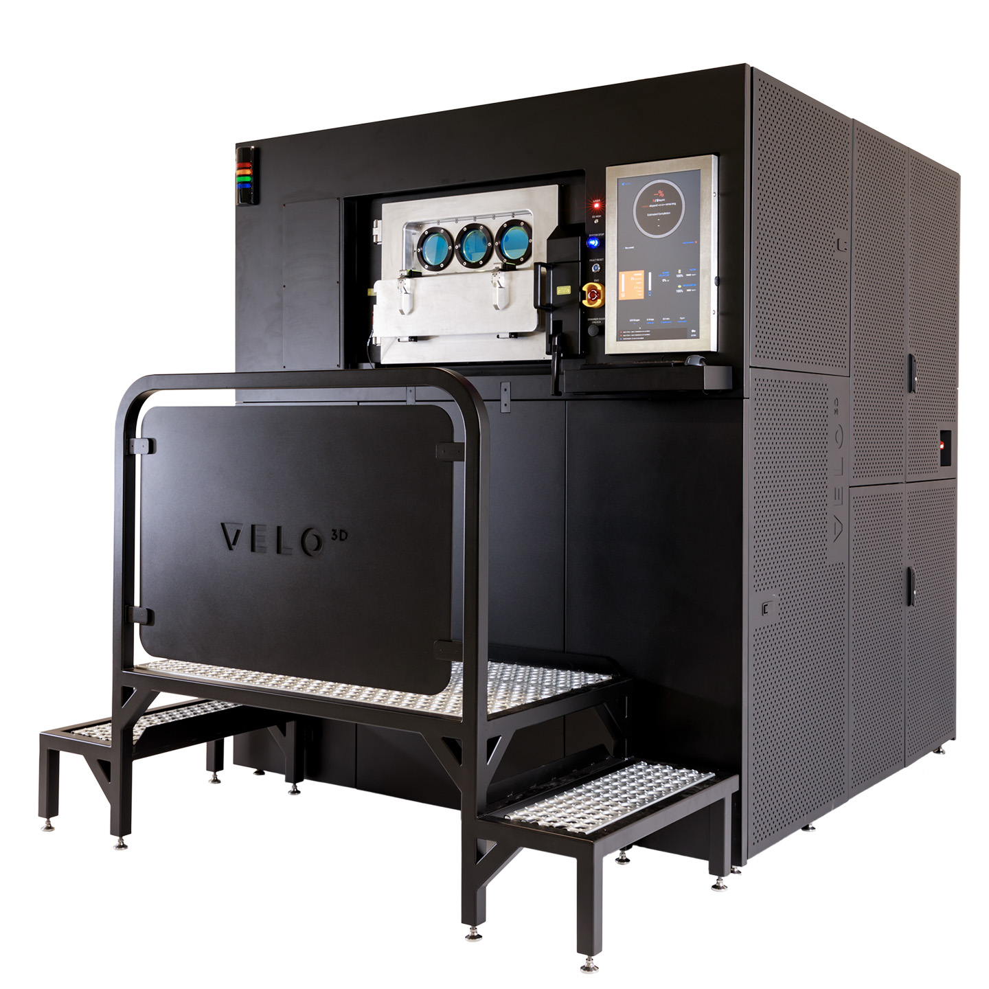
VELO3D’s Metal Printer Tackles Design and Build Limitations

After working under the radar for many years, California-based VELO3D finally emerged as one of the most promising startups in August 2018 with the release of its Sapphire metal 3D printer. The company developed a metal printing process with more design freedom in metal, able to print complex geometries below 45 degrees, and reduce part costs by 30 to 70 percent, which would make more 3D printed parts possible. Based on the company’s Intelligent Fusion technology, the system comes with fewer constraints than other printers, becoming the only metal laser system with support-free capability and an end-to-end integrated workflow, which many consider will change metal 3D printing forever. 

Brian Spink

Now, thanks to a free webinar hosted this month by the company’s Applications Engineering Manager, Brian Spink, the firm is taking metal 3D printing engineers and specialists through the design process for VELO3D’s Sapphire System, discussing the considerations to keep in mind when selecting parts for their printer, including a deep understanding of angle and floating geometry guidelines, as well as their advanced non-contact recoater mechanism (a truly revolutionary invention).


“Designing parts for VELO3D‘s Sapphire printer has fewer restrictions than other systems. In fact, you may not need to redesign your parts at all since the technology can print support-free in a wider range of geometries and has overcome the 45-degree rule, with a first print success rate of 90 percent, and parts that meet and exceed metal manufacturing density requirements over 99.9 percent,” suggests Spink,

VELO3D‘s Sapphire printer is a next-generation laser fusion metal AM system designed for advanced 3D metal printing. While conventional 3D printing systems often require supports for any geometry below 45 degrees, VELO3D’s Sapphire uniquely enables engineers to realize designs with overhangs lower than 10 degrees, and large inner tubes up to 40 mm without supports. Some applications can even be printed free-floating in the powder bed, built layer by layer in Inconel 718 (IN718) or Titanium alloy (Ti6Al4V), using two powerful kW lasers and a patented non-contact recoater. The technology is designed from the ground up with high volume manufacturing in mind featuring a 315 mm diameter by 400 mm height build envelope. Additionally, and to maximize productivity, Sapphire also features integrated in-situ process metrology that enables first-of-a-kind closed loop melt pool control.

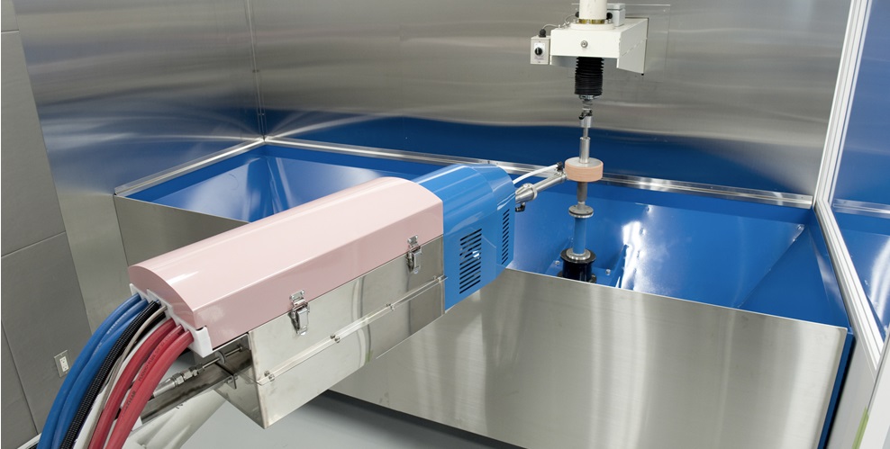
Sapphire laser fusion system

The development is truly a game-changer. Users typically had to go through an iterative redesign process in order to make parts that are suitable for additive manufacturing, meaning an extra design effort. During the webinar, the expert explained that there is no support needed for overhangs over 15 degrees for both materials: Inconel and Titanium. Usually, supports have to be designed up-front in order to keep the parts from warping, and then, once the part is built, they have to be removed, which leads to costly post-processing.

“In general, the way people address residual stress along the part is to just add support material. Supports help, but they are not the only way to build and they also introduce other issues, such as restraining or anchoring the part down to keep it from warping up and also acts as energy sync,” he said. “There are major drawbacks to these supports which is why VELO3D does not want to include them, allowing for some unique processes to run through,” Spink went on.

VELO 3D controls the thermal/mechanical behavior of the geometry through proprietary hardware and advanced process controls. The system recognizes many more unique geometries, especially using angle based rules to apply unique processes to the geometries, to avert more control and have a fuller experience without breaking down. 

“Another added level of control that VELO3D has introduced is a closer control for certain process parameters. We have a couple of sensors that monitor the melt pool in real time, and using this data we can recreate a close loop that can adjust the laser parameters–also in real time–to help control the consistency of the melt pool and avoid breakdowns.”

A heat exchanger made in Inconel

“In some of these cases, we are taking something that couldn’s be done with any other AM process and enabling it on the VELO3D system, such as with dome closures where internal cavities have manifold type geometries that can be printed using the firm’s technology without adding support.”

According to Spink, being able to print the feature without supports is highly dependent on the angle normal to the surface, but also on other driving factors that determine angle-based rules, including the curvature of the leading-edge of growth of the part, the number of layers the geometric feature propagates, the laser angle of incidence relative to the angle of growth, and other local geometric characteristics that affect how the energy is being absorbed and how the melt pool is behaving locally.

“Every geometry is unique so its hard to generalize an exact rule for an infinite amount of parts, this is why we are attempting to give the users a couple of proxies and a handfull of rules on simple geometries so that they may interpolate them on other geometries they are experiencing with.”

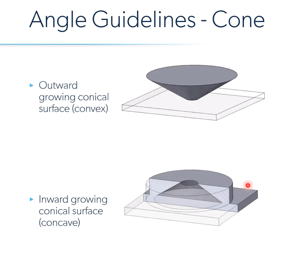
The specialist explained how to deal with plane and conical geometrical shapes, suggesting, via a “Probability of Breakdown” graph, whether and when the geometry needs to be constrained. The angle guidelines for the conical shapes–which are simple proxy– reveal that an outward growing conical surface (convex) has a higher probability of breakdown once it goes above a full height of 5 mm, meaning it is quite risky, and at 10 mm it behaves at very high risk. Spink suggests that in this cases two basic forces are working together that may lead to breakdowns: global residual stress which is shrinking each layer by pulling the geometry inward towards the local mass, and the other is a skin process that forms a ring around the geometry that contracts and wants to pull it inward. 

Otherwise, an inward growing conical surface (concave) geometry at a 10-degree angle is very stable and does not require support because the probability of breakdown is very low.

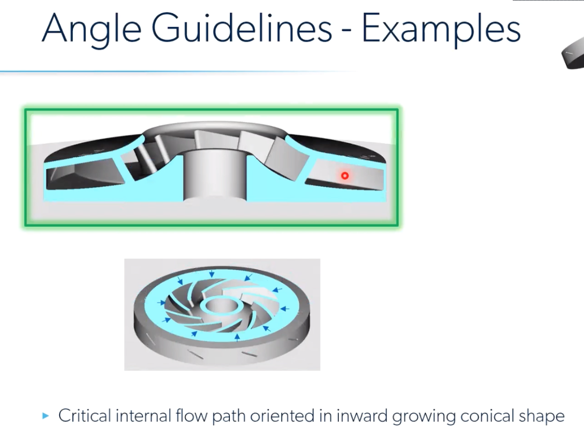
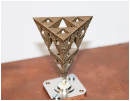
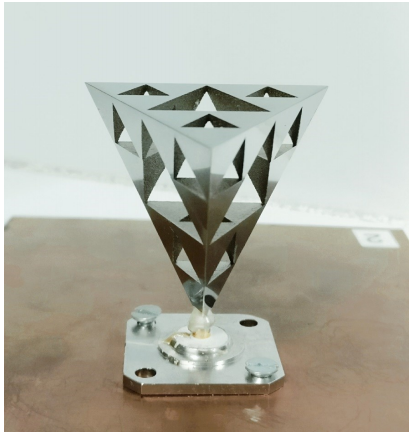
Example: strut and impeller mock up

To better understand how conical geometries work in VELO3D, Spink suggests looking into a strut and impeller example, which has a critical internal flow path when it is oriented in an outward growing conical shape (convex) and if it is not supported, there is a high risk of breakdown. This conical shape is going to behave pretty unfavorably and put the user at a higher risk when he or she avoids adding supports. So by flipping it into a concave conical shape, the relatively high-risk downfacing surface keeps the same angle range but the general shape is an inward growing conical one that can maintain stability and avoid breakdowns in the process without having to add supports. 

VELO3D systems also have the ability to print floating parts, which means they are not attached to the build plate at all or any other surface in the build volume, which means no added support material.

“The build starts in powder and the main enabler here, aside from the process control, is the unique non-contact recoater mechanism (which applies a fresh layer of powder on the print bed, making it ready for a pass by the lasers for selective fusing). Because there is no interference between the part, which is now floating loose in the powder, you will find it very rewarding to open a build chamber and simply reach in to pull the part out, without having to remove any support material attached to it,” Spink explained.

There are a few rules for the floating geometries. They must originate from a small-cross section or point of geometry, meaning you can’t print a large flat plane because there will still be residual stress even with VELO3D’s unique processes. And the second main rule is that there must be one powder start and no connection with the build plate. 

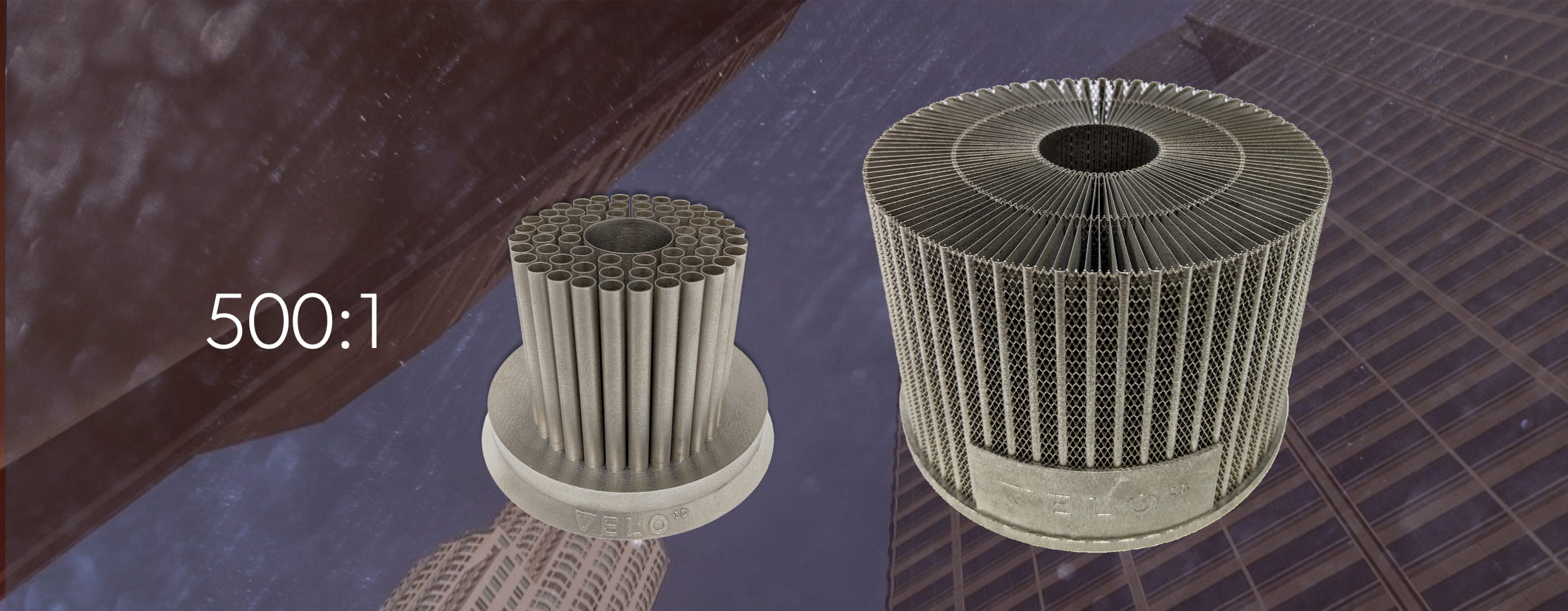
VELO3D still has a strong process development team working on ongoing research and development, especially regarding stability on existing processes and spearheading other efforts, but most experts agree that the powerful 3D metal printing technology they have developed is groundbreaking. As you can see in the VELO3D images and videos, there is a lot of detail and accuracy in the geometries. These capabilities mean that the Sapphire System can now print objects that were impossible on other 3D printing systems. VELO3D says they can even achieve a 500:1 aspect ratio on structures, as opposed to the more typical 10:1 ratio on competing systems (or even less 4:1 or 5:1 on other powder bed fusion machines), but you should probably try it out for yourself and see what it is all about.

[Images: VELO3D]

The post VELO3D’s Metal Printer Tackles Design and Build Limitations appeared first on 3DPrint.com | The Voice of 3D Printing / Additive Manufacturing.

Sciaky Joins R&D Initiative to Combine Traditional Metallurgy with Wirefed Metal 3D Printing Techniques

Metal 3D printing solutions provider Sciaky, Inc., well known for its extremely popular Electron Beam Additive Manufacturing (EBAM) process, just announced that it has entered into a research and development initiative with metallurgist expert Aubert & Duval – a subsidiary of the Eramet group’s Alloys division – and Airbus, one of its previous 3D printing partners. The ambitious initiative, also called the Metallic Advanced Materials for Aeronautics (MAMA) project, is being driven by the Saint Exupéry Institute for Research in Technology (IRT), and the academic partner for the project is the Production Engineering laboratory of the National School of Engineering in Tarbes, France.

“Sciaky is proud to work with the Saint Exupéry IRT, Aubert & Duval and Airbus on this exciting project. Industrial metal additive manufacturing technology continues to break new ground every day, and Sciaky is committed to keeping EBAM at the forefront of this movement,” said Scott Phillips, the President and CEO of Sciaky, Inc., a subsidiary of Phillips Service Industries, Inc. (PSI).

In terms of work envelope, Sciaky’s exclusive EBAM technology is probably the most widely scalable metal AM solution in the industry. It’s the only industrial metal 3D printing process that has approved applications for air, land, sea, and space, with gross deposition rates up to 11.34 kg of metal an hour, and is able to manufacture parts from 203 mm to 5.79 meters in length. Rather than just melting the outer layer of the metal powder, the EBAM process completely liquefies the metal wire feed.

The fast, cost-effective EBAM process offers a wide range of material options, including titanium, for large-scale metal applications, and uses its adaptive IRISS (Interlayer Real-time Imaging and Sensing System) to combine quality and control, as the patented system can sense, and digitally self-adjust, metal deposition with repeatability and precision. It is mainly due to the IRISS system that the Chicago-based company’s EBAM 3D printing process is so good at delivering, as the company puts it, “consistent part geometry, mechanical properties, microstructure, and metal chemistry, from the first part to the last.”

The goal of its combined MAMA project with Airbus and Aubert & Duval is to combine traditional metallurgy (high-power closed die forging) with new wirefed metal 3D printing techniques, such as Sciaky’s EBAM process, in order to come up with new processes for manufacturing titanium alloys that can be used to make aircraft parts. Based on the caliber of its partners, Sciaky made a good decision in joining the R&D initiative – Airbus is a 3D printing pioneer in the aerospace industry, and Aubert & Duval creates and develops advanced metallurgical solutions for projects in demanding industries, such as nuclear, medical, energy, defense, and aeronautics.

The project’s first phase has global funding in the amount of €4.2 million. 50% of this funding is supported by the French State as part of its “Investing in the Future” program (Programme Investissement d’Avenir, or PIA), while the other half is funded by industrial partners of the initiative.

Discuss this story and other 3D printing topics at 3DPrintBoard.com or share your thoughts in the Facebook comments below.

[Images provided by Sciaky, Inc.]

Processing Parameters in SLM 3D Printing: UK Researchers Test Ti6Al4V Cellular Structures

In ‘The influence of processing parameters on strut diameter and internal porosity in Ti6Al4V cellular structure,’ UK researchers from the University of Birmingham look further into strut size and porosity issues during bioprinting, and discuss the overall challenges of selective laser melting (SLM) in additive manufacturing. In this research, SLM 3D printing was used to create Ti6Al4V cellular structures, but with a wide range of different parameters.

While porous structures are attractive in many applications today for industries like automotive and aerospace, when created with titanium alloys they ensure strength, corrosion resistance, and the proper amount of density required. Even more importantly, however, lattice structures like Ti6Al4V offer high biocompatibility. Made up of a network of struts that form cells to make lattices, these complex structures are often manufactured with conventional techniques like casting; however, with AM technology, complex geometries can be produced faster and more affordably.

As the researchers point out however, problems can occur in SLM printing when conditions are not properly optimized—resulting in defects due to a ‘mismatch’ between the 3D design and the 3D print. The team set up an experiment for testing parameters and pinpointing a way to improve SLM methods.

Lattice structure fabricated
using SLM

They created a set of structures ranging from 100W to 300W and scan speed ranging 8000 mm/s to 4000 mm/s. Lattices were assessed regarding the effects of input energy on strut diameters, and porosity levels. As they suspected due to compiled data from previous research studies, increased input energy resulted in increased strut diameters:

“This relation is attributed to the fact that inclined struts were built partially on loose powder, which resulted in adhesion of free powder (partially melted powder particles) to the surfaces of the struts. At high input energy condition, the energy transferred to attach powder particles was high enough to result in full melting of the attached powders and hence became part of the fabricated strut.”

Different zones were created based on changes in input energy:

  • Zone 1 – low input energy was directed here, leading to ‘discontinuity’ in the strut. The researchers noted this was due to lack of diffusion between melt pools, along with a balling effect that typically causes defects in SLM.
  • Zone 2 – as the zones ascend in energy, this one is a result of intermediate laser power and scan speed. The researchers noted the formation of irregular defects, again, without diffusion between melt pools. They also noted erratic formation in the struts, resulting in ‘waviness.’
  • Zone 3 – this zone formed with the pairing of higher laser power but low scanning speed, ‘mitigating the previously formed lack of diffusion defects.’

A diagram showing the variation of Strut diameter as a function of increasing linear input energy diameter.

“SLM processing parameters investigated in the current research shows that the input energy density has a significant influence on the strut diameter and porosity morphology within the fabricated struts. Different zones were developed based on changing the input energy,” concluded the researchers.  “Additionally, it was observed that strut diameter size for Ti6Al4V lattice structure increased with increasing the input energy density.”

While much about 3D printing can be deceptively simple, additive manufacturing processes are often more complicated in hardware, software, materials required, and technique. Selective laser melting, although it may offer some challenges, continues to be at the forefront of research projects and studies today, from new procedures created for heat accumulation detection to fabricating steel nuclear components or working with metallic glass. Find out more about strut diameter and porosity issues with this method too here. What do you think of this news? Let us know your thoughts! Join the discussion of this and other 3D printing topics at 3DPrintBoard.com.

SEM images for struts at different fabrication conditions (a) 100W &4000mm/s (b) 200W & 2400mm/s
(c) 300W & 800mm/s

[Source / Images: The influence of processing parameters on strut diameter and internal porosity in Ti6Al4V cellular structure]

Titomic Signs MoU with China’s Lasting Titanium to Secure Supply of Metal 3D Printing Powders

Titomic, a top metal 3D printing company in Australia well known for its innovative Kinetic Fusion technology, announced that it has just signed its latest Memorandum of Understanding (MoU), this time with Shaanxi Lasting Titanium Industry Co. Ltd, which is China’s largest manufacturer and global exporter of titanium powder and titanium alloy products.

The new MoU, which will commence immediately, will allow Titomic to secure a high quality supply of low-cost, commercially pure titanium powders from Lasting Titanium for use with its Kinetic Fusion technology, which includes benefits such as the ability to join dissimilar metals and composites for engineered properties in a single structure and a decreased time to market, thanks to its high deposition speeds.

“This MoU will provide exclusive supply of large volumes of price point titanium powder for use in Titomic’s TKF systems to create new commercial opportunities for titanium in traditional industries in a more efficient and sustainable way for industrial scale manufacturing,” said Jeff Lang, Titomic’s Managing Director.

Headquartered in Xi’An, Lasting Titanium has spent the last two decades supplying titanium products to multiple industries around the world, including aerospace, automotive, defense, medical, and 3D printing. In addition, Lasting Titanium, which has achieved international ISO, AMS, ASTM, and MIL standards across multiple industries, is also involved in research regarding rare metal production, forging, finishing, rolling, smelting, non-destructive testing, and both physical and chemical analyses.

The new partnership between Titomic and Lasting Titanium will, according to a Titomic press release, “enable the cooperative development of new titanium powders for Titomic Kinetic Fusion,” as well as attain an exclusive supply of new price point powders for Titomic’s technology.

Titomic’s unique Kinetic Fusion can be used to manufacture large parts with heat-related distortion or oxidation issues, so there are no size or shape constraints when it comes to the rapid 3D printing of large, complex parts. The process works by spraying titanium powder particles at supersonic speeds of about 1 km per second, using a 6-axis robot arm, onto a scaffold. These particles move so fast that when they collide on the scaffold, they fuse together mechanically to produce huge, load-bearing 3D forms.

The Kinetic Fusion process is also versatile enough to use both spherical and irregular morphology metal powders to 3D print industrial scale metal products, which provides the company with additional opportunities in industries like automotive, marine, building, and oil & gas that previously could not apply titanium due to a lack of economic viability.

L-R: Lasting Titanium’s Gloria Wang, Cai Longyang, Zheng Xiaofeng, and Wang Qi Lu, and Titomic’s Jeff Lang and Vahram Papyan.

Lasting TItanium’s irregular powder morphology is the perfect fit for industrial scale 3D printing with Titomic’s Kinetic Fusion systems. By using this irregular titanium powder, Titomic’s customers will be able to access “a price point alternative” that will go well with the company’s additional range of aerospace-grade and mid-end titanium powders; other 3D printing methods can’t use this price point irregular powder in the same way, which will set Titomic apart in its field.

The new MoU between Lasting Titanium and Titomic will open up new commercial opportunities for 3D printed titanium products over multiple industries, and will specifically create a viable way for Titomic’s Kinetic Fusion systems to compete with traditional methods of manufacturing.

Discuss this news and other 3D printing topics at 3DPrintBoard.com or share your thoughts in the Facebook comments below. 

Student Takes A Look at Several Metal 3D Printed Antennas for Thesis Paper

In a thesis entitled “Design of Microwave Components using Direct Metal Laser Sintering,” a Waterford Institute of Technology student named Deepak Shamvedi discusses using 3D printing to fabricate several microwave components, including the first-ever 3D printed metal Sierpinski gasket antenna, with multiple resonance characteristics. Shamvedi chose the Sierpinski gasket antenna because of its complexity, aiming to “push the limits of 3D metal printing.”

The antenna was 3D printed using the EOSINT M280 machine and a titanium alloy called Ti-6Al-4V.

“Following the rules of 3D printing, one should acknowledge that even though the Sierpinski fractal design may look simple, but it is complex at the same time,” states Shamvedi. “It consists of an arrangement of stacked pyramids one-upon-another, to form a 3D geometry. A rectangular copper clad PCB ground plane, of 160 mm x 100 mm, with 1 mm thickness, has been used to serve as a finite ground plane to the printed antenna.”

Because the 3D printed version of the antenna could not be realized with infinitely small joints, Shamvedi had to print it in an upside down orientation with a minimum of 1.90 mm base diameter (0.95 mm base radius). This value was chosen to achieve the 3D design without any metal drooping. The base diameter also needed to be big enough to facilitate soldering if needed. The base diameter of the antenna formed a ring-like shape, due to which the effect of the RF performance of the antenna, from increasing or decreasing the width of the ring, has been named the “ring width effect.”

Support structures were required; in order to make them easier to remove, Shamvedi added small holes in the CAD design of the supports. Once the antenna was 3D printed, it underwent a rigorous post-processing routine to remove the supports and reduce the surface roughness of the component. The antenna was then mounted onto feeding circuitry for RF measurements, which were carried out after each stage of post-processing, including wet blasting and polishing, to assess the affect of the surface roughness on the antenna’s performance.

“From the results obtained, increased surface roughness increases the random scattering of electromagnetic waves; therefore, increasing RF resistance, which further reduces the gain of the antenna,” explains Shamvedi. “The antenna RF performance was measured and found to be in good agreement with simulation results, in terms of bandwidth and radiation characteristics.”

Experimental prototype of a monocone antenna

Shamvedi also 3D printed a monocone antenna and integrated an N-type feed onto it to create a monolithic structure. 3D printing, he explains, produces fine detail and robust components with low surface roughness. A monolithic structure can also offer better mechanical properties over glue or solder. Despite some challenges, Shamvedi was able to produce a working prototype of a 3D printed antenna, and the measured RF results for the antenna were found to be in good agreement with the CST simulation results.

Shamvedi then compared the performance of three metal 3D printed antennas to that of polymer ones. A metal 3D printed inner lattice antenna possessed higher strength-to-weight ratio than a metal-coated polymer antenna. He also investigated the effects of surface roughness on a 3D printed metal horn antenna, and explored 3D printing as a means to improve the performance of an X-band horn antenna, with the primary goal of side-lobe reduction. Finally, he 3D printed an artificial dielectric lens for applications including 5G.

Discuss this and other 3D printing topics at 3DPrintBoard.com or share your thoughts below.


Subjecting 3D Printed Medical Ti6Al4V Implants to Laser Peening Could Increase Wear Resistance

When it comes to manufacturing biomedical implants, whether they’re 3D printed or not, titanium alloys are often used, and one of the most common is medical Ti6Al4V, thanks to its biocompatibility, mechanical properties, and excellent corrosion resistance. However, its use is not widespread due to its poor wear resistance. Additionally, the simultaneous action of both corrosion and wear could result in increased degradation of implants made with this alloy, as well as generate high wear debris, which limits stability. So it’s important to improve the alloy’s wear resistance in corrosive body fluid, in order to extend the service life of 3D printed implants made with medical Ti6Al4V.

(a) A schematic view of LP path and (b) Detection program.

Many researchers are using surface modification techniques, like thermal oxidation and plasma surface alloying, to beef up the wear resistance. But the thermal effects of these methods can cause tensile residual stress in treated materials’ surface layer, which can then decrease fatigue strength.

That’s why a group of researchers from Jiangsu University are turning to laser peening (LP), a laser surface modification technology, instead. They recently published a paper on their efforts, titled “Effect of laser peening on friction and wear behavior of medical Ti6Al4V alloy.”

The abstract reads, “The aim of this study was to investigate the effects of laser peening (LP) on the friction and wear properties of medical Ti6Al4V alloy. Wear tests were conducted on the samples before and after LP with a ball-on-disk wear tester in Hank’s solution. The surface roughness and micro-hardness of the differently treated samples were measured. The friction and wear properties of the samples were evaluated by comparing their coefficient of friction (COF) and wear mass loss. The morphologies of wear scar and the wear mechanism were characterized by optical microscope (OM), scanning electron microscope (SEM) and energy dispersive spectrometer (EDS). The results showed that the surface micro-hardness of the specimen subjected to LP was significantly increased by 25.7% and the corresponding depth of the hardened layer was more than 0.3 mm. The average COF and wear mass loss were significantly reduced to 50% and 29.2%, respectively, as a result of the increasing laser energy and impact times. After LP, the wear mechanism turned from the severe oxidative wear to a slight adhesive wear and abrasive wear. Experimental results proved that LP treatment could effectively improve the friction and wear properties of the medical Ti6Al4V alloy.”

SEM micrographs of worn surface of untreated and LP treated specimens. (a) and (b) Specimen 0 (untreated); (c) Specimen 1 (1 impact-4 J-LP); (d) Specimen 6 (2 impacts-8 J-LP).

Laser peening uses severe plastic deformation, induced by plasma shock wave, to modify a material’s mechanical and microstructural properties, and other studies have shown that the method can refine the grain and improve microhardness of a material’s surface layer. When used with the proper treating parameters, LP can also improve the corrosion resistance and fatigue behaviors of metals and alloys – good news for 3D printed implants. But there hasn’t been a lot of research conducted on the wear and friction properties of medical Ti6Al4V alloy subjected to LP…until now, anyway.

“This paper aims to investigate the effects of LP on wear and friction behavior of medical Ti6Al4V alloy with different laser peening parameters in Hank’s balanced salt solution (HBSS),” the researchers explained. “Surface roughness and micro-hardness of the samples were measured, while their friction coefficient and wear mass loss were also investigated. Surface morphologies of wear scar on the sample were observed by a 3D optical microscope, and the wear mechanisms of the specimens before and after LP in simulated human body fluids were discussed based on SEM images and EDS data.”

The team used a commercially available medical Ti6Al4V alloy for the experiment, and cut samples into 40 x 20 x 4 mm rectangular shapes, with 4 mm thickness.

(a) Samples used in the wear test; (b) Schematic illustration of the wear test system.

Untreated and LP-treated Ti6Al4V specimens were tested for surface roughness and micro-hardness, and sliding wear tests were conducted at Nanjing University of Aerospace and Astronautics in China.

“During the test, the sample was immersed in Hank’s solution at room temperature and fixed in the rotating cup,” the researchers explained.

“The rotating cup was used to rotate the samples at a speed of 120 r/min for 30 min with wear radius of 3 mm. GCr15 ball (750 HV, Ra < 0.1 μm) of 8 mm diameter was used as the counter material. The test load was 5 N throughout the process which is closer to the condition of biomedical implant application. In all of the tests the COF were monitored against time directly through the elastic cantilever and sensors of this system.”

3D morphology (a–c) and section profile (d) of wear scar: (a) Specimen 0; (b) Specimen 1; (c) Specimen 6.

The samples were cleaned after the tests, and had their wear mass loss measured. Additionally, a 3D optical microscope was used to observe the 3D morphology of the wear scars, and SEM, combined with an energy dispersive spectrometer, observed their worn surfaces.

The team concluded that, when compared to the untreated sample, the surface micro-hardness value of the LP-treated Ti6Al4V sample increased by 25.7%, showing that LP was able to strengthen its surface. Additionally, the results of the experiment showed that after being treated with LP, the specimen did have better wear resistance than the untreated one; laser energy and impact time also helped improve the wear resistance of the LP specimen.

“After LP treatment, the wear mechanism of the Ti6Al4V specimen changed from severe oxidative wear into slight adhesive wear and abrasive wear,” the researchers wrote. LP process could contribute to the inhibition of toxic elements that are released in the human body when Ti6Al4V alloy implants are utilized.”

Co-authors of the paper are Jianzhong Zhou, Yunjie Sun, Shu Huang, Jie Sheng, Jing Li, and Emmanuel Agyenim-Boateng.

Discuss this and other 3D printing topics at 3DPrintBoard.com or share your thoughts below. 

Captiva Spine Receives FDA Clearance for 3D Printed Titanium Lumbar Cages

3D printing has been playing a big role in helping people with spinal conditions over the last few years, particularly in terms of implants and other medical devices. But none of these 3D printed spinal solutions can get too far without the necessary clearance from the FDA. Florida-based Captiva Spine, Inc., a privately owned medical device organization that was founded in 2007, recently received 510(k) clearance from the FDA for its 3D printed TirboLOX-L Titanium Lumbar Cages.

“With the advanced capabilities of 3D Additive Manufacturing we were able to create a unique lattice structure similar to trabecular bone incorporating a micro-rough surface for clot retention and early osteogenic cell migration, including a dual layer of porosity with pore sizes specifically designed to promote bone ingrowth and vascularization,” said Dennis Ty, the Director of R&D of Captiva Spine. “Through substantial surgeon design input we are able to deliver TirboLOX-L’s unique dual layer organic lattice structure with numerous geometries and sizes that appeal to a wide range of surgeon preferences.”

The company helps spine surgeons, healthcare facilities, and tenured spine distributors that work to provide patients with progressive, high quality spinal care. It’s dedicated to providing elegant and intuitive spinal fusion solutions, such as its TirboLOX-L Titanium Lumbar Cages. This spinal implant uses 3D printing to form interbody fusion devices, made out of titanium alloy, with a double layer organic lattice structure.

The lattice structure has an open architecture, a micro-rough surface topography, and interconnected dual porosity. The architecture can help lower radiographic presence to ensure clear imaging, while implants that possess the latter two features have shown that they can promote bone ingrowth, ongrowth, and vascularization. In addition, Captiva’s TirboLOX-L has a high coefficient of friction, which, as the company puts it, “creates immediate bidirectional fixation.”

Some of the main benefits of 3D printed porous titanium alloy cages, like the TirboLOX-L lumbar cages made of Titanium Alloy (Ti-6Al-4V), is bone’s ability to successfully grow within its architecture, which can then help it achieve good kinematic properties. The TirboLOX-L Titanium Lumbar Cage also features the company’s Pivotec technology.

“I am pleased our development team was able to incorporate our proprietary Pivotec Pivoting TLIF Cage into TirboLOX,” said Dale Mitchell, the President and Founder of Captiva Spine. “Pivotec technology has been used in thousands of surgeries to address the challenges of controlling cage insertion and angle manipulation during surgery and is now available in a wide range of porous Titanium 3D printed, sterile packaged implants. This is especially important during minimally invasive (MIS) applications where time and safety is always of the essence.”

With FDA clearance, Captiva is now cleared to take its 3D printed TirboLOX-L Titanium Lumbar Cage to market. This device is also one of five new product launches that the company is featuring at the upcoming North American Spine Society (NASS) Annual Meeting later this month in Los Angeles. Stop by its booth #1649 at the meeting to see the other four.

Discuss this story and other 3D printing topics at 3DPrintBoard.com or share your thoughts below. 

3D Printing Golf Clubs and Equipment

Golf is a popular sport in corporate America and adds about $70 billion dollars a year to the American economy. Companies are always testing new products that will catch the attention of golfers. The 2018 PGA Merchandise Show displayed the latest and greatest from golf manufacturers; everything from top of the line golf clubs to 3D printed golf balls. These tech savvy products are aimed at bringing golf to the attention of the younger generation. Research and Development tax credits are available to companies that partake in the improvement of existing products or the creation of new ones.

The Research & Development Tax Credit

Enacted in 1981, the federal Research and Development (R&D) Tax Credit allows a credit of up to 13 percent of eligible spending for new and improved products and processes. Qualified research must meet the following four criteria:

  • New or improved products, processes, or software
  • Technological in nature
  • Elimination of uncertainty
  • Process of experimentation

Eligible costs include employee wages, cost of supplies, cost of testing, contract research expenses, and costs associated with developing a patent. On December 18, 2015, President Obama signed the bill making the R&D Tax Credit permanent. Beginning in 2016, the R&D credit can be used to offset Alternative Minimum Tax and startup businesses can utilize the credit against $250,000 per year in payroll taxes.

3D Printed Callaway Golf Clubs

Callaway Golf recently announced a collaboration with Titomic, an Australian additive manufacturing company. Callaway plans to bring additive manufacturing into the golf world while also improving performance and efficiency. Titomic developed a new process for 3D metal printing called Titomic Kinetic Fusion. This process uses cold gas spraying to apply titanium particles to a structure to create parts that can withstand a great amount of force. Research and development of the prototypes will be produced at Titomic’s Melbourne facility which houses the world’s largest 3D metal printer. This isn’t the first instance of additive manufacturing in the golf industry, as last year Krone Golf created a 3D printed golf club.

Krone Golf

Krone Golf and CRP Group designed a club that was created by using a mixture of additive manufacturing and subtractive manufacturing. Designing the perfect golf club is a difficult task. Some aspects to take into consideration include swing, impact and follow-through. Restrictions such as size and weight of competitive golf clubs make it hard to develop new clubs. The miniscule characteristics of a club need to be altered in order to improve performance and additive manufacturing provides a way to make the changes needed for the development of new clubs. The body of the KD-1 driver is made from a Windform SP carbon composite that is resistant to shock and vibration, while the face is made of Ti 6AI-4V, a durable titanium alloy that is CNC machined and sanded for smoothness. Krone Golf is fascinated with how well the CNC machined parts and the Windform material work together exactly as designed. The performance test and computer simulations show the KD-1 to outperform any driver on the market today.

Grismont Paris

Golfers who want to separate themselves from the crowd will want to look to Grismont Paris. Grismont Paris produces 3D printed, custom-made golf clubs that can be finished in gold, copper, or metal. Clement Pouget-Osmont, a passionate golfer, started off making club heads for himself and friends out of his apartment in France. Now Grismont collaborates with engineers, artists, craftsmen, and clubmakers to create custom tailored 3D printed golf clubs unlike anything else on the market.

3D printing artists work together with engineers to create a harmonious balance between style and performance. Several aspects of a golf club can be adjusted to better fit the customer including center of gravity position, lie, loft, offset, club head weight, weight distribution, and  handedness. You have the option to either put in your specifications online or you can arrange a fitting session where experts will tailor your golf clubs to your every demand.

3D Printed Golf Ball

Nike is prototyping a 3D printed golf ball that is engineered to last longer and outperform even the best of golf balls on the market. Nike isn’t new to producing top of the line golf balls. The athletic company still uses elastomeric material for an inner core and a rigid material for an outer core, but 3D printing improves this process by conducting smoother transitions between materials and adding a new type of geometric configuration called a void, which could lead to performance enhancements. Nike is prototyping with different configurations, such as forming each shell layer away from the work surface, a type of assembly that is unattainable through traditional methods. Lastly, golf balls would be fused with DuPont Surlyn by using a 3D printing technique called fused deposition. While the golf ball is not on the market yet, expect Nike to announce the product in the near future.

3D Printed Accessories

For the golfers who want to 3D print on their own, Thingiverse has creations available to anyone. Makerbot, the company behind Thingiverse, designed a golfing kit that anyone can print. The kit includes CAD models for golf tees, golf forks (divot repair tool), and ball marker. The golf fork and ball marker can even be customized to display your initials or logo on the face.

Conclusion

The golf industry is constantly trying new methods of manufacturing in the quest for better performance. Club manufacturers, even brand names such as Callaway, are utilizing 3D printing in the production process in order to improve the smallest technical aspects of the golf club unattainable using traditional manufacturing methods such as injection or compression molding. Grismont is taking 3D printing to the next level by 3D printing custom-made heads and fine tuning them into top-of-the-line luxury golf clubs. 3D printing has a strong future in the golf industry and as more companies research the potentials of additive manufacturing, expect 3D printed products to become widespread in the golfing world.

Discuss this and other 3D printing topics at 3DPrintBoard.com or share your thoughts below. 


Charles Goulding and Ryan Donley of R&D Tax Savers discuss 3D printed golf equipment.