3D Printing: Successful Scaffolds in Bone Regeneration

In ‘Comprehensive Review on Full Bone Regeneration through 3D Printing Approaches,’ the authors review new developments and solutions in tissue engineering for the formation of cells, as well as proposing an optimized temporary support geometry for treatment.

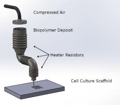
Fused Filament Fabrication (FFF) process.

Bone regeneration continues to challenge researchers in their work as well as medical professionals attempting to improve patient treatment:

“Many research groups have been working on bone regeneration for over 10 years, but this has not led to effective therapy in a clinical setting. If it was successful, it would enhance the quality of life for millions of people and significantly reduce the absence to work due to fractures which are considered the second higher cause of working day lost,” state the authors.

“When there are fractures with a bone defect exceeding a critical size, the bone is not able to self-regenerate and, therefore, requires the use of a temporary implant (natural and/or synthetic) to serve as support and cells to help bone regeneration. In this way, tissue engineering (TE) has emerged.”

While scaffolds are used in tissue engineering for transporting nutrients and secretion of waste, the cells must be able to imitate true tissue biology, morphology, and functionality.

Exploring the usefulness of temporary implants, the authors state that in tissue engineering for patients, it is first critical to examine native bone tissue and mechanical properties.

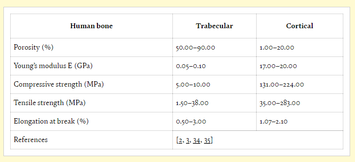
Human long bone properties.

3D printed implants must be able to sustain cell viability in a secure environment, and scaffolds must possess suitable elasticity for matching regular bone. High porosity is desired in most tissue engineering, along with the use of materials that are not only biocompatible but also biologically active. During trials, animal models of fractures are often used in vivo before procedures are attempted on humans.

“Animal studies are needed to understand bone regeneration. Variables such as the amount of bone formation and its kinetics, mechanical properties and safety obtained by the scaffold, including the presence of toxic degradation in different organs and in terms of inflammatory response need to be understood in detail,” explained the researchers.

“However, bone fractures performed in animals do not represent the complexity of healing human fractures. The potential of each different type of cells both in vitro and in vivo plays here a key role.”

Even more interesting though, the authors point out that growth factors are unnecessary, with cells showing the potential to secrete optimal extracellular matrix (ECM) components.

“In vitro studies are advantageous because they offer a controlled environment to experimental test molecular and cellular hypotheses,” stated the researchers. “However, cells cultured in vitro are not replicates of their in vivo counterparts.”

While tissue engineering can be a delicate process overall in terms of working to keep cells alive, bone generation is particularly challenging—and scaffolds must be relied on to maintain the same role as tissue. Biomaterials must be able to mimic the natural environment, along with possessing identical mechanical properties of the initial bone. Appropriate levels of degradation are critical for bone regeneration, and are also dependent on corrosion resistance and materials.

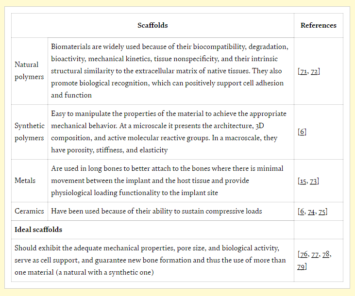
Characteristics of the different materials used to produce a scaffold.

Suitable materials include poly(ε-caprolactone) (PCL) or polylactic acid (PLA), both approved by the FDA and offering stability, biocompatibility, and biodegradability. Scaffolds must be osteoinductive for sustaining cells as well as being osteoconductive, providing growth. They must also serve to:

  • Fill bone defect
  • Ensure pore connectivity
  • Encourage bone formation
  • Promote bone growth

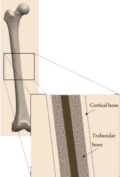
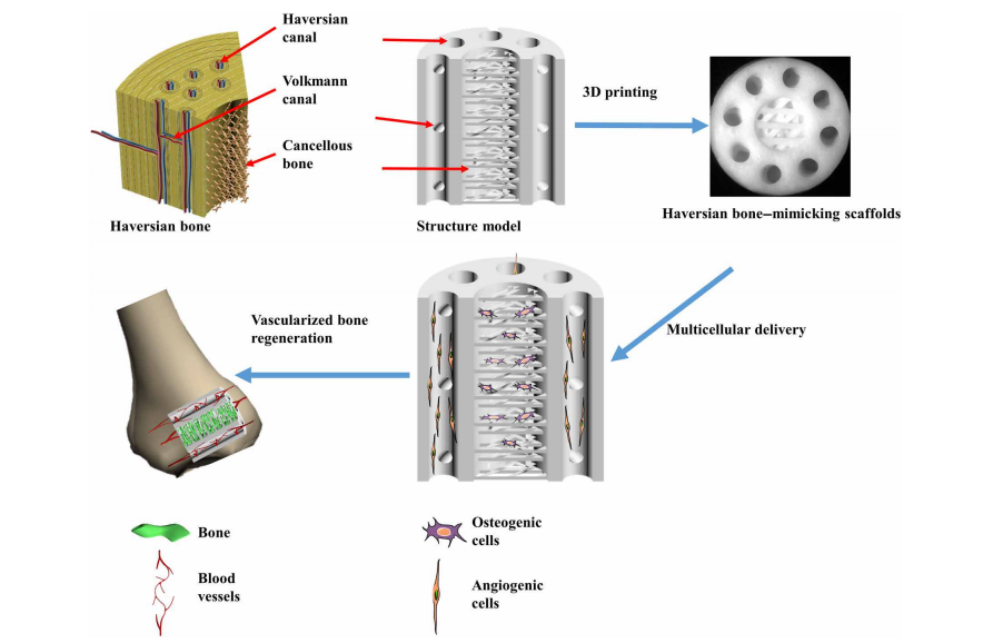
Natural organization of long bones.

Designed in SolidWorks, the structures exhibited ‘superior advantages’ over what could be produced conventionally.

“Considering all types of materials available, associated with the desired bone regeneration and the use of synthetic polymers, as PCL or PLA, combined with collagen type I for the trabecular region and Hap for cortical region, seems to be the best strategy to follow,” concluded the researchers.

“Among the most commonly used bioreactors for bone regeneration, perfusion bioreactors appear as the most suitable, because it improves osteogenic proliferation and differentiation due to improved mass transfer and adequate shear stress. When making a design proposal for bone regeneration, it is necessary to study the mechanical effects, such as stress and tension, and link them.”

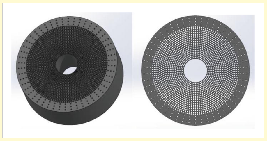
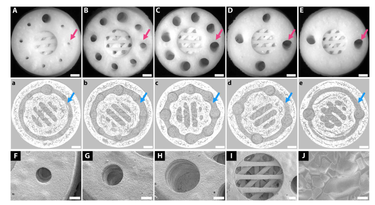
Cylindrical scaffold

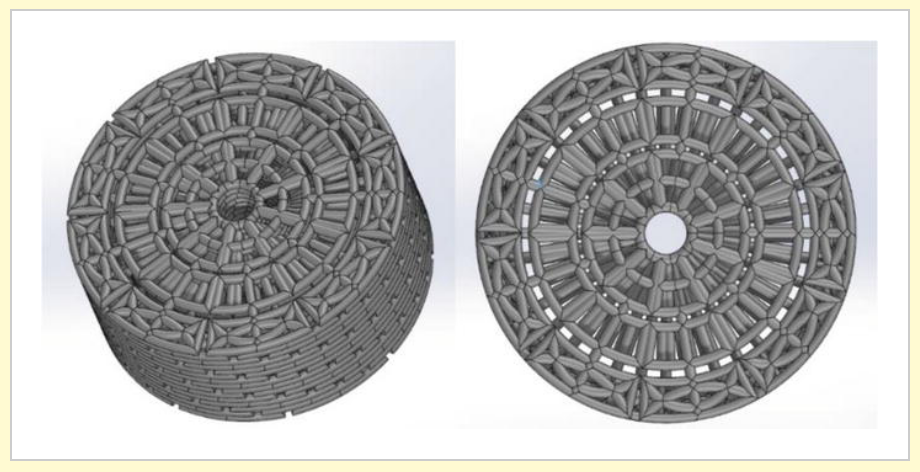
DNA chain-inspired cylindrical scaffold.

Tissue engineering continues to be an enormous area of study, from seeding human dermal fibroblasts, promoting hydrogel microenvironments, to bioprinting structures for soft tissue engineering applications.

Scaffold requirements in terms of response (left) and what should be taken into account (right) (adapted from [106]).

What do you think of this news? Let us know your thoughts! Join the discussion of this and other 3D printing topics at 3DPrintBoard.com.
[Source / Images: ‘Comprehensive Review on Full Bone Regeneration through 3D Printing Approaches’]

The post 3D Printing: Successful Scaffolds in Bone Regeneration appeared first on 3DPrint.com | The Voice of 3D Printing / Additive Manufacturing.

Denmark: 3D Printing Conductive Hydrogels for Medical Applications

In the recently published ‘Electrically Conducting Hydrogels for Health care: Concept, Fabrication Methods, and Applications,’ Shweta Agarwala of the Department of Engineering at Aarhus University in Denmark researchers 3D printing techniques in the medical realm, offering a review of conductive hydrogels.

As 3D printing began to infiltrate the mainstream, industries such as automotive, aerospace, and construction have been positively impacted—and now, medical applications have gone beyond 3D models and devices as scientists continue to make huge strides in bioprinting. Scaffolds are a common structure used in tissue engineering featuring a variety of different hydrogels; however, they can also be used for a wide range of applications today, from smart wearables to biosensors, implants, and avenues to wound management.

Hydrogels are attractive for use in research and other applications due to:

  • Ideal extracellular matrix (ECM)
  • Cell support
  • Biocompatibility
  • Natural and synthetic hydrophilic polymer chains offering high absorption of water

“Although hydrogels have found niche application in tissue engineering, they are inherently insulating by nature. Recent research has shown that hydrogels not only possess necessary characteristics to support biological species but can also interface with electrical circuitry if modified,” states Agarwala. “Hence, research on conducting hydrogels have gained widespread interest for applications such as health recording electrodes.”

Schematic illustration of conducting hydrogels, their components and applications.

Agarwala notes that in general, the conductivity associated with hydrogels is ionic conductivity.

Summary of the material composites and their electrical conductivities achieved to make conducting hydrogels.

“The contribution from additives materials to overall conductivity in such cases is small. However, recent research efforts in this direction have shown promise in inducing electrical conductivity from the additive materials,” states Agarwala.

While the method most often used for aqueous compatible conducting materials is to use ultrasonic energy or heating, five other approaches are available:

  1. Hydrogel monomers with cross-linkers and nanoparticles are gelated together.
  2. Nanoparticles are physically embedded into the hydrogel matrix after gelation.
  3. Nanoparticle precursors are loaded into the gel.
  4. Cross-linking using nanoparticles forms hydrogels.
  5. Hydrogels are formed using nanoparticles, polymers, and other molecules.

Schematic diagram depicting various approaches to synthesize conducting hydrogel: (A) hydrogel monomers with cross-linkers and nanoparticles gelated together; (B) physically embedding nanoparticles into hydrogel matrix after gelation; (C) reactive nanoparticle formation aided by the hydrogel network where nanoparticle precursors are loaded in the gel; (D) cross-linking using nanoparticles to form hydrogel; and (E) hydrogel formation using nanoparticles, polymers, and other molecules.

One of the greatest benefits in 3D printing is that users are able to create much more complex geometries, along with enjoying enormous latitude in both design and customization, as well as being able to make projects faster, and make changes to them on demand. All of these benefits apply to why there has been such an increase in 3D printing conducting hydrogels.

Techniques usually rely on shear thinning, causing them to flow as pressure is applied, using a piezoelectric head.

“A piezoelectric material deforms on applying voltage or current. Thus, the orifice opening can be controlled by varying the voltage applied to the printer head. Inkjet printing creates small droplets (sub-micron volume), which are deposited on the surface,” states Agarwala. “Small volume of material deposition, as against large material ejection through extrusion, helps to print high-resolution constructs and scaffolds.”

“Ink development is considered one of the most important aspects of 3D printing. Hydrogel inks need to have the right rheological properties to fulfill the physical and mechanical needs of the orienting process.”

Sketch of (A) 3D bioplotting system (Reproduced with permission [65]) (B) digital light projector (DLP) 3D printing system to 3D print conducting hydrogel scaffolds (Reproduced with permission [74]), and (C) stereolithography process (Reproduced with permission [75]).

Such hydrogels have the potential to be used in sensor technology, drug delivery systems, and tissue engineering. A variety of composites have been used too, from graphene-chitosan to silica nanoparticles, silica alumina, but the author points out that commercialization of such manufacturing is ‘still far away,’ due to the many challenges involved.

“These materials are unable to follow the original design models, as the printed construct does not retain the original shape. Achieving functional gradients and hierarchical properties have also been challenging and new design approaches are being developed to tackle them,” concludes Agarwala. “

“The area of conducting hydrogels is still full of unresolved technological challenges, and thus provides researchers with opportunity for development, as this field is growing fast beyond its early stage. Improvement in the conductivity of the hydrogels may be one research direction, while incorporating new functionalities such as biodegradability and mechanical strength can open new avenues for applications. Innovation is also required in fabrication methods to allow varied composition of hydrogels to be laid down in desired fashion.”

What do you think of this news? Let us know your thoughts! Join the discussion of this and other 3D printing topics at 3DPrintBoard.com.

[Source / Images: ‘Electrically Conducting Hydrogels for Health care: Concept, Fabrication Methods, and Applications’]

The post Denmark: 3D Printing Conductive Hydrogels for Medical Applications appeared first on 3DPrint.com | The Voice of 3D Printing / Additive Manufacturing.

3D Printed Haversian Bone: Biomimicking for Cell Regeneration

Chinese researchers continue to take on the challenge of bone regeneration in tissue engineering, sharing their findings in the recently released ‘3D printing of Haversian bone—mimicking scaffolds for multicellular delivery in bone regeneration.’

The fabrication of scaffolds is at the center of successful bone regeneration, but this is an area of medicine that is still known to be difficult—despite a wide range of research projects performed already, from using variations in nanotubes to structures with controlled antibiotic release, alternative materials and coatings.

As the authors point out, while bioprinting is an area of medical research where scientists have made huge strides, there are several reasons that obstacles remain:

  • Complexity of hierarchical structures
  • Mechanical property requirements
  • Diversity of bone resident cells

Most regeneration occurs in cancellous bone, however, so this is what researchers must focus on for success in treating patients:

“Cancellous bone is a meshwork consisting of plate-like or rod-like structures at about 200-mm thickness,” explained the authors. “By one estimate, 80 percent of bone remodeling processes occur in cancellous bone. However, bone regeneration not only needs to reconstruct bone structure but also involves repairing other tissues like blood vessels or nerves.”

Biomimetic structures are showing great potential as ‘high-performance bone tissue engineering biomaterials,’ however, leading the research team to focus on the use of 3D printed Haversian bioceramic structures which can imitate bone in a ‘simple but versatile design.’

3D printing Haversian bone–mimicking scaffolds integrated with Haversian canals, Volkmann canals, and cancellous bone structure for delivery of osteogenic and angiogenic cells. Osteogenic cells were seeded in cancellous bone structure of scaffolds, and angiogenic cells were seeded on Haversian canals. The Haversian bone–mimicking structure–based multicellular delivery system contributed to the formation of new bone and new blood vessels.

Due to superior osteoconductivity and osteoinductivity, materials composed of akermanite were used in fabrication of five samples with varying measurements in canals and cancellous bone serving as meshwork.

3D printing of Haversian bone–mimicking bioceramic scaffolds with cortical bone and cancellous bone structure. Cortical bone structure contained Haversian canals and Volkmann canals. (A to E) Optical microscope images exhibited different diameters (D) and numbers (N) of Haversian canal indicated by magenta arrows (A) N = 8, D = 0.8 mm; (B) N = 8, D = 1.2 mm; (C) N = 8, D = 1.6 mm; (D) N = 4, D = 1.6 mm; and (E) N = 2, D = 1.6 mm. Scale bars, 1 mm. (a to e) Micro–computed tomography (CT) images show Volkmann canals (blue arrows) connecting Haversian canals in the interior of scaffolds. Scale bars, 1 mm. (F to J) SEM images presented the microstructure of the scaffolds.

“Interconnected Haversian canals were isolated from the cancellous bone structure for noncontact cell coculture,” stated the researchers. “Furthermore, the periphery and bottom of the scaffolds were sealed so that the scaffolds could be used for holding the seeded cells.”

Several different techniques were necessary in creating the scaffolds, to include using electrospinning and twin-screw extrusion, modular tissue engineering, and 3D printing. The team had the most success with DLP 3D printing, designing a series of structures with Haversian canals, Volkmann canals, and cancellous bone.

Haversian bone–mimicking bioceramic scaffolds for the HBMSC-HUVEC coculture system performed better in cell proliferation and angiogenic differentiation than monoculture. (A to D) CLSM images of HBMSCs seeded on the cancellous bone structure (A) and HUVECs seeded on the Haversian canal with different diameters, (B) D = 1.6 mm, (C) D = 1.2 mm, and (D) D= 0.8 mm. Scale bars, 100 m. (E to H) SEM images of (E) HBMSCs seeded on the cancellous bone structure and HUVECs seeded on the Haversian canal with different diameters of (F) 1.6 mm, (G) 1.2 mm, and (H) 0.8 mm. (I and J) The proliferation activity of HBMSC, HUVEC, and cocultured HBMSC-HUVEC seeded on scaffolds with different (I) diameters and (J) numbers of Haversian canals after culturing for 1, 3, 7, and 14 days. n = 6 replicates. (K and L) The osteogenic (K) and angiogenic (L) gene expression of HBMSC, HUVEC, Co-HBMSC (HBMSCs in HBMSC-HUVEC coculture), and Co-HUVEC (HUVECs in HBMSC-HUVEC coculture) for 3 days. n = 3 replicates. *P < 0.05, **P < 0.01, ***P < 0.001, $ P < 0.05, $$P < 0.01.

Haversian bone–mimicking bioceramic scaffold–based rBMSC-rSC coculture system performed better in cell proliferation and neurogenic differentiation
than monoculture. (A to D) The CLSM images of rBMSC in the (A) rBMSC monoculture group and rBMSC-rSC coculture group with the ratio of rBMSC to rSC being (B) 3:7, (C) 5:5, and (D) 7:3 seeded on the cancellous bone of scaffolds. Scale bars, 50 m. (E to H) The CLSM images of rSCs in (E) the rSC monoculture group and rBMSC-rSC coculture group with the ratio of rBMSCs to rSCs being (F) 3:7, (G) 5:5, and (H) 7:3 seeded on the Haversian canal of scaffolds.

“Here, we further established the Haversian bone–mimicking scaffold–based rBMSC-rSC coculture system with rBMSCs grown in cancellous bone structure and rSCs grown on Haversian canals. Our results indicated that the rBMSC-rSC coculture system exhibited a better proliferation and a higher expression of NGF, BDNF, TrkA, and S100 as compared to rSC monoculture,” concluded the researchers. “It was found that BMSCs could promote SC proliferation and were traditionally used to facilitate the recovery of sensory system.”

“Considering the clinical applications of Haversian bone–mimicking scaffolds, there are still some issues to be studied. First, more bone-resident cells such as osteoblasts, osteoclasts, and macrophages should be further considered in the coculture system. The mechanism of multicellular synergistic effects is not fully understood. Further studies are needed to identify the individual effects of coculture cells on the formation of new bone, blood vessels, and nerves in the Haversian bone–mimicking scaffold–based coculture system.”

What do you think of this news? Let us know your thoughts! Join the discussion of this and other 3D printing topics at 3DPrintBoard.com.

[Source / Images: ‘3D printing of Haversian bone—mimicking scaffolds for multicellular delivery in bone regeneration’]

The post 3D Printed Haversian Bone: Biomimicking for Cell Regeneration appeared first on 3DPrint.com | The Voice of 3D Printing / Additive Manufacturing.

Cartilage Tissue Engineering via Characterization and Application of Carboxymethyl Chitosan-Based Bioink

International researchers continue the trend in exploring natural biomaterials for bioprinting, detailing their findings in the recently published ‘Characterization and Application of Carboxymethyl Chitosan-Based Bioink in Cartilage Tissue Engineering.’

Examining chitosan as an ingredient for bioink in cartilage tissue engineering, the authors realize previous challenges in using printable inks overall—along with difficulty in sustaining cells in the lab environment. Such material has been featured in 4D printing studies, along with experimentation in bioprinting with chitosan-gelatin hydrogels.

Chemical crosslinking has also been used by many research teams, employing chemicals like glutaraldehyde, formaldehyde, and carbodiimide; however, many such agents are high in toxicity, leading to negative reactions. Because chitosan is a natural polysaccharide, it is being used more often in bioprinting applications.

Schematic diagram of hydrogel preparation and printing. (a) First step: chitosan reacting with EDTA, unreacted carboxyl groups (green) take part in the next step. (b) Second step: additional chitosan is added to the solution and crosslinked with CaCl2 solution after printing to form hydrogel. (c) Hydrogel printing method.

For this study, the researchers focused on tissue engineering of cartilage, seeking ways to regenerate cells:

“The characteristics of chitosan are similar to those of hyaluronic acid and glycosaminoglycans which are distributed extensively in native cartilage, and the degraded products of chitosan are involved in chondrification,” stated the researchers. “However, the weak mechanical property of pristine chitosan limited its further utilization in cartilage regeneration, and the poor water solubility hinders the large-scale use.”

To overcome hurdles for the development of materials with chitosan, the authors developed ink with ‘enhanced mechanical properties,’ allowing them to print hydrogel templates for cartilage bioprinting. Relying on carboxymethyl chitosan, hydrogels were suitably complemented.

Bioink was created via both pneumatic and piston-driven methods (Hkable 3D):

“In order to maintain the continuity of printed hydrogel line and prevent clogging at the extruder, the diameter of the needle used for 3D printing in this work was 0.5 mm, the air pressure was controlled by an affiliated precise regulator and set at 110 psi, and the travel speed of the extruder was set to 300 mm/min.”

Printed samples with different chitosan : modified chitosan (CE) ratios. Images on the left, from top to bottom, show highly viscous bioink resulting in a discontinuous print, highly viscous bioink printed using a large diameter needle resulting in an inaccurate print, and low-viscous bioink incapable of holding its shape after printing. Image on the right shows an accurate printed structure with a chitosan : CE ratio of 90 : 10.

Four bioink samples were evaluated in the study, compared as CE powder weight was kept the same for all but the amount of added chitosan was varied. Experimentation revealed that greater amounts of CE caused higher storage and loss modulus, as it proved also to be the main factor in strength enhancement.

(a) Storage and (b) loss modulus of chitosan/CE hydrogel. Four Chitosan/CE conjugate ratios tested. (c) Storage modulus (G′) and loss modulus (G″) of the bioink as a function of crosslinking time. Solid lines represent 45 min of crosslinking, and dashed lines represent 30 min of crosslinking. CaCl2 (1 M) solution is used as the crosslinking agent

Effect of crosslinker concentration on gel retraction and appearance. Images of hydrogel discs crosslinked with (a) 0.1 M, (b) 0.5 M, (c) 1 M, and (d) 2 M CaCl2 solution. Top images in each set represent gel precursor before the final crosslinking, and bottom images represent the resulting gel after crosslinking. The chitosan/CE conjugate ratio of the samples shown is 90 : 10, and the crosslinking time is 45 min for all samples.

(a) Live/dead staining of chondrocytes. (b) Flow cytometry result of cell viability in the control group. (c) Flow cytometry result of cell viability in the hydrogel mesh group. (d) Quantification of cell viability in both groups. Scale bar = 100 μm.

Overall, the bioink showed stability and mechanical properties required for both fast gelation and precision in bioprinting.

“According to the rheology and mechanical testing results, the bioink viscoelastic properties and mechanical strength are tunable by adjustment of the proportions of the components which provides a platform to expand the application of the bioink in tissue engineering,” concluded the authors.

“Furthermore, cell studies with chondrocytes show that the bioink is biocompatible, and it supports cell proliferation as well as helps cells to retain their chondrogenic phenotype. Our results illustrate that the developed bioink has the potential to be adopted for 3D bioprinting of scaffolds for tissue engineering.”

What do you think of this news? Let us know your thoughts! Join the discussion of this and other 3D printing topics at 3DPrintBoard.com.

[Source / Images: ‘Characterization and Application of Carboxymethyl Chitosan-Based Bioink in Cartilage Tissue Engineering’]

The post Cartilage Tissue Engineering via Characterization and Application of Carboxymethyl Chitosan-Based Bioink appeared first on 3DPrint.com | The Voice of 3D Printing / Additive Manufacturing.

Italy: Studying Properties & Geometry of Scaffold-Like Structures for Tissue Engineering

Italian authors Claudia Pagano, Lara Rebaioli, Francesco Baldi, and Irene Fassi explore the unique details of creating scaffold-like structures in the recently published ‘Mechanical behavior of scaffold-like structures: Research of relationships between properties and geometry.’ In this study, the focus is on scaffold geometry and stability, and how mechanical properties are affected.

Scaffolds today are used in a wide range of tissue regeneration and engineering applications, serving as porous structures based on networks promoting the growth of human tissue. The researchers realized for this study that it was critical to confirm the relationship between stiffness and strength and the size of samples in ‘polymeric parts’ structured like scaffolds. PLA ‘scaffold-like samples’ were printed and tested for tensile strength, slicing the 3D models in Simplify3D using a Sharebot NG 3D printer. Samples were printed to include ten replicates for each height of 6, 12, 18, and 24mm.

a) Model of the structure geometry b) specimen examples

Each of the specimens was evaluated regarding density, porosity, and mass.

Picture of the compression test set-up

Loading curves for each specimen demonstrated:

  • First region (R1) – load increases linearly
  • Second region (R2) – characterized by abrupt reduction of slope
  • Third region (R3) – just beyond the knee

“By analogy with the behavior of cellular materials, and by considering the compression direction and the specific 3D structure, it is likely that: in the linear elastic region R1, the load is mostly borne by the material in the filament junctions of the adjacent layers; at the knee (R2), the plastic collapse of the structure occurs, based on localized yielding phenomena of the constituent polymer; in R3, the porous structure undergoes a progressive accumulation of plastic deformation and the filaments crash together, resulting in an evident distortion of the specimen.”

a) relative stiffness b) relative strength

The authors also note that because of the polymer strength offering more influence, ‘with respect to stiffness,’ that element should be taken into account when selecting material to build a structure; in fact—and of course this makes sense in any construction project—a comprehensive knowledge is critical to the success of any design and consequent structure that is created later.

“In case the mechanical behavior of a typical scaffold structure could be described by referring to properties intrinsic to the system (independent on the geometry/size) the structure could be treated as an effective ‘3D material,’ and the scaffold design could be easily produced and its performance predicted,” concluded the researchers.

“Several parallelepiped-shaped specimens with different sizes have been fabricated and their mechanical stiffness and strength measured by compression tests. The results have showed that the porosity degree controls the stiffness and strength of the 3D structure. Only the strength, taken as the stress at failure, is intrinsic to the examined structure (thus behaving as a ‘3D material’ concerning the mechanical strength), whereas for the stiffness, a specimen size dependence has been observed. The polymer properties have a stronger influence on the 3D structure strength rather than on its elastic response.”

The successful fabrication of scaffolds is becoming more important to research today—and to patient-specific treatment in areas such as bone replacement, mesh reinforcements, and classic tissue engineering.

What do you think of this news? Let us know your thoughts! Join the discussion of this and other 3D printing topics at 3DPrintBoard.com.

[Source / Images: ‘Mechanical behavior of scaffold-like structures: Research of relationships between properties and geometry’]

The post Italy: Studying Properties & Geometry of Scaffold-Like Structures for Tissue Engineering appeared first on 3DPrint.com | The Voice of 3D Printing / Additive Manufacturing.

Researchers Recreate Hopping Disney/Pixar Lamp with 3D Printed Actuator

3D printing has previously been employed to create passive mechanisms and machines, as well as the actuators used to make them go. According to a new paper, titled “A Miniature 3D Printed On-Off Linear Pneumatic Actuator and Its Demonstration into a Cartoon Character of a Hopping Lamp,” using 3D printing to create actuators can speed up design and development, save on time and money, and allow for greater customization. Christian L. Nall from the University of Texas at San Antonio and Pranav A. Bhounsule from the University of Illinois at Chicago wrote and published the paper, which presents their work creating and fabricating a small double-acting, On-Off type linear pneumatic actuator with FDM 3D printing.

“In this paper, we explore the use of 3D printing to create a pneumatic actuator and its utility on a legged robot,” the pair wrote.

“The actuator has an overall length of 8 cm, a bore size of 1.5 cm, and a stroke length of 2.0 cm. The overall weight is 12 gm and it generates a peak output power of 2 W when operating at an input air pressure of 40 psi (